 Input/Output
SCI
Arbiters can use up to three serial SCIs (Serial Communication Interface). Serial ports A, B and C parameters can be edited in this menu to fit the serial protocol requirements.
Note
SCI A corresponds to RS-232 port A (RS232-1), SCI B to RS-232 port B (RS232-2) and SCI C to RS-485.
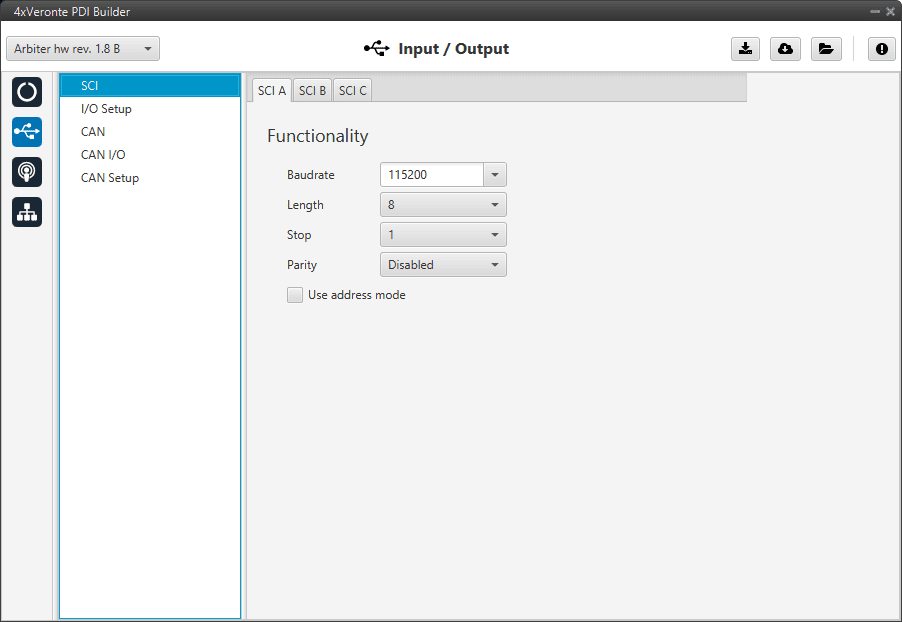
SCI panel
Baudrate: How fast data is sent over a serial line.
Length: Number of data bits for each character: 4 to 8 bits.
Stop: Number of stop bits sent at the end of each character: 1, 1.5 or 2.
Parity: Is a method of detecting errors in transmission. When parity is used with a serial port, an extra data bit is sent with each data character, arranged so that the number of 1 bits in each character, including the parity bit. Disabled, odd or even.
Use address mode: 9-bit data framing uses the bit typically associated with parity error detection to identify address messages. Sent serial data that does not have the address bit set will be ignored (unless the device had previously identified an address message associated with it). This option can be disabled or enabled.
I/O Setup
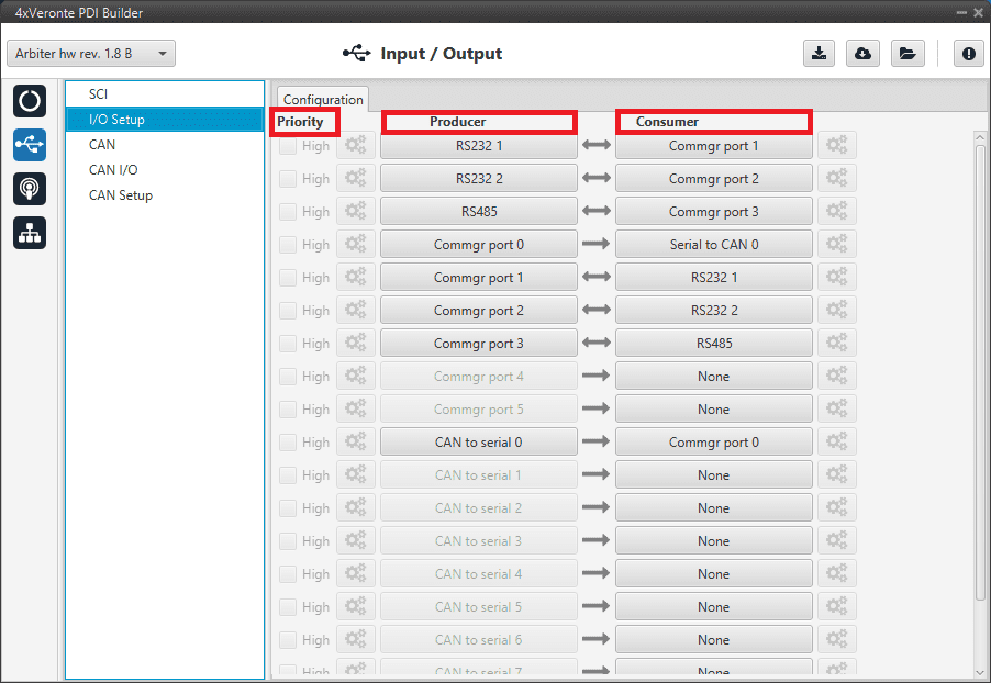
In this panel the user can establish the relationship between a determined signal with a I/O port. This allows users to configure external sensors, custom messages, etc.
I/O Setup panel
Priority: Certain connections between I/O ports can be marked with high priority with this checkbox. If it is enabled, they will run at high frequency: 1000 Hz.
Producer: Functions to create and send messages.
Consumer: Functions to receive and parse messages.
The following are the steps to setting up reception or transmission between ports:
Choose the Producer to use.
To configure the desired Consumer that will be bind to the chosen Producer, it is first required to establish the relationship between them:
Bind \(\rightarrow\): Unidirectional relationship.
Bind Bidirectional \(\leftrightarrow\): Bidirectional relationship. This enables a port to receive or send information.
Note
Once the Consumer has been selected, it is possible to undo the selection by pressing the Clear button.
Select the desired Consumer element.
The following I/O ports are available:
Field |
Description |
|---|---|
RS232 1 |
Serial Port 232 A |
RS232 2 |
Serial Port 232 B |
RS485 |
Serial Port 485 |
Commgr port |
COM Manager ports send and receive VCP messages. This is the protocol used by Veronte products to communicate. For more information, read the VCP user manual |
CAN to serial / Serial to CAN |
Serial to CAN sends serial streams over a CAN Bus / CAN to serial undoes the transformation ‘Serial to CAN’ |
CAN wrapper for serial transmission / CAN message unwrapper for serial transmission |
CAN wrapper for serial transmission sends CAN streams over a serial Bus / CAN message unwrapper for serial transmission undoes this transformation. For more information on these ports, please refer to CAN wrapper/CAN unwrapper - Input/Output section of the 1x PDI Builder user manual |
Warning
By default, RS232 1-2 are set up for Arbiter configuration.
If these connections are removed, it will not be possible to communicate with the Arbiter in Normal mode. In this situation, force the arbiter into Maintenance mode in order to recover the communication.
CAN
A CAN (Controller Area Network) Bus is a robust standard communication protocol for vehicles widely used in the aviation sector. The Management Board has two CAN buses that can be configured independently.
The structure of a CAN message can be seen in the following image:

CAN message structure
Only the ID is introduced in the system, the rest of the message layout is already coded. The data field is built by the user to send, and parsed when received.
For more information on the CAN Bus protocol, see CAN Bus protocol section of the 4x Software Manual.
The baudrate of both CAN buses can be configured in the Baudrate box.
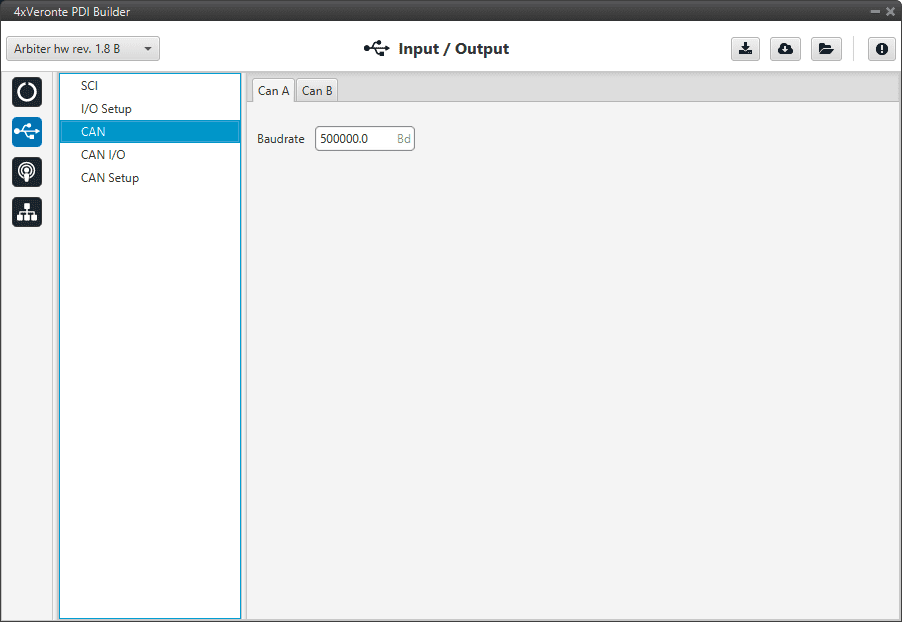
CAN panel
CAN I/O
Configuration
This panel allows the configuration of CAN communications between different devices.
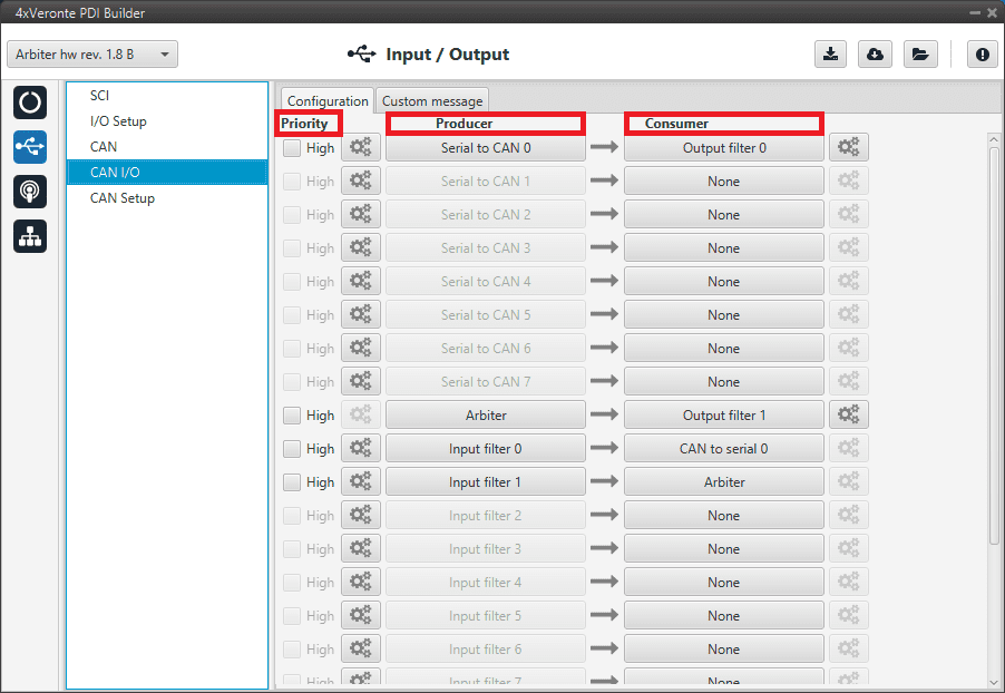
Configuration panel
In this panel, the user can find the same ‘columns’ (Priority, Producer and Consumer) as in the I/O Setup panel. In addition, the process for configuring producers and consumers is also the same as described in the I/O Setup - Input/Output section.
Warning
In CAN, in Low state the specified period is not guaranteed, but it is guaranteed with High state.
However, only those messages that are critical for external devices should be set as high priority, as this may disrupt the proper functioning of the arbiter.
Producers:
Arbiter: It sends a status and a score mesage.
To know more, read Arbitration messages - CAN Bus protocol section of the 4x Software Manual.
Serial to CAN: Serial messages through CAN output, it has to be connected to I/O Setup consumer. It can be configured by clicking on
 , a pop-up window will appear:
Serial to CAN configuration
Id: CAN Id must be set and it is used to identify messages. The value set has to be decimal format.
Extended: If it is enabled, the frame format will be ‘Extended’, i.e. with a 29-bit identifier. Otherwise, the frame format ‘Standard’ (11-bit identifier) is set by default.
Time out: This is the threshold time between receptions to consider that it is not being received correctly.
Input filter: Those CAN messages received in one filter can no longer be received in subsequent filters. The following parameters need to be configured by clicking on
:
Input filter configuration
Port: It is required to configure the CAN bus from which it listens, the user can choose between CAN A, CAN B or BOTH.
Id: CAN Id must be set and it is used to identify messages. The value set has to be decimal format.
Mask: A CAN Id mask can be set to filter messages. The mask defines which bits of the message id (in binary) should match.
For example, to admit standard Ids (11 bits) from 8 to 11 (100 to 111 in binary) the user should set the mask to binary 11111111100, that is 2044 in decimal.
Warning
Make sure that mask is set properly to be able to receive the desired CAN messages.
The mask should be 11 bits for Standard frame format and 29 bits for Extended frame format.
More information about this can be found in How to calculate a mask - FAQ section of this manual.
Filter type: The available options are Standard (frame format with a 11-bit identifier), Extended (frame format with a 29-bit identifier) and Both.
Custom messages: CAN custom messages transmission. They are configured in the next panel, explained in thr Custom message section of the present manual.
CAN unwrapper: This undoes the ‘CAN wrapper’ action, it has to be connected to I/O Setup consumer (CAN unwrapper for serial transmission)..
Consumers:
Arbiter: It sends ready and arbitration messages.
To know more, read Arbitration messages - CAN Bus protocol section of the 4x Software Manual.
CAN to serial: This undoes the ‘Serial to CAN’ action, it has to be connected to I/O Setup producer.
Output filter: CAN output filters. The user can choose between CAN A, CAN B or BOTH in the configuration button
.
Output filter configuration
Custom messages: CAN custom messages reception. They are configured in the next panel, explained in thr Custom message section of the present manual.
CAN GPIO consumer: CAN message from Veronte Autopilot 1x for GPIO inputs. An example of how to implement it can be found in the GPIO command - Integration examples section of this manual.
CAN wrapper: CAN message through serial output, it has to be connected to I/O Setup producer (CAN wrapper for serial transmission).
Warning
The Input filter connected to the Arbiter consumer must have a mask that allows all arbitration CAN IDs.
Custom message
In this tab, the user chooses the variables to be sent/received through CAN buses. The following elements can be configured:
TX Ini: It is used to configure transmitted messages that are only sent once at the beginning of the operation (sent when the arbiter boots up). They can be used to initialize some devices.
TX: Configuration for transmitted messages.
RX: Configuration for the reception messages (where they are stored).
Warning
The maximum capacity of a CAN message is 64 bits (8 bytes), so to send more information it must be divided into several messages.
Each arbiter has a CAN limitation of 40 TX messages, 40 TX Ini messages and 80 RX messages. In addition, the following limits apply:
Maximum number of vectors (fieldset): 104
Maximum number of fields: 2000
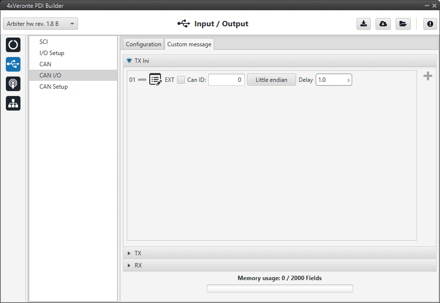
Custom message panel
Since this section works in a similar way to the CAN Custom Message configuration in the 1x PDI Builder software, the explanation on how to configure the telemetry messages via CAN is reflected in the Custom Messages - Input/Output section of the 1x PDI Builder user manual.
CAN Setup
In this screen, users can configure the baudrate and reception mailboxes of each CAN Bus.
Since the arbiter is going to receive data on the CAN Bus, it is mandatory to configure a certain number of mailboxes to store that data until the arbiter reads it.
A mailbox can be configured for multiple CAN message IDs as long as the mask is configured correctly and these messages are sent spaced out with enough time between them to allow the high priority core to read each one individually. More information on masks can be found in How to calculate a mask - FAQ section of this manual.
Warning
Since 4x PDI Builder allows up to 32 mailboxes, users should make sure to leave at least one mailbox free for transmission (TX).
If any mailbox is full and another message arrives, the new message is discarded.
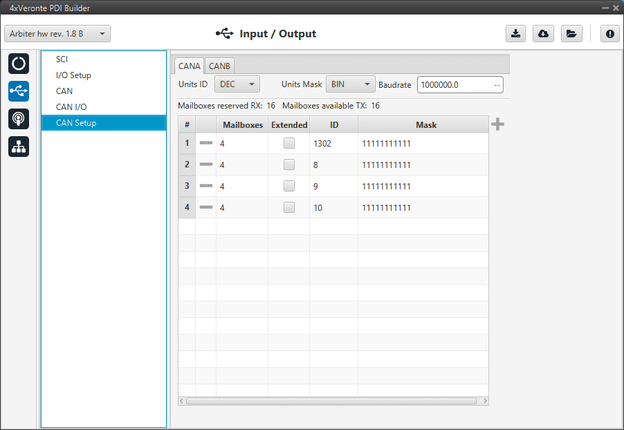
CAN Setup panel
More information about mailboxes can be found in the Mailboxes - Input/Output section of the 1x PDI Builder user manual.