 Arbiter
GPIO
In this window, each individual GPIO (General Purpose Input/Output) behavior can be configured:
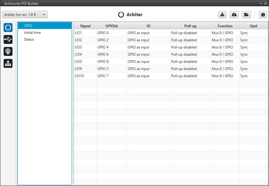
GPIO panel
Signal: Pin ID as described in Arbiter connector pinout - Hardware Installation section of the 4x Hardware Manual.
GPIOId: GPIO ID of the microcontroller.
IO: Define GPIO as an input or ouput.
Pull-up: Enable or disable the pull-up resistance.
Function: Mux 0/GPIO, Mux 1, Mux 2 or Mux 3. These are the different functionalities that the GPIO can have, depending on the multiplexer.
Qsel: This is the “input qualification”, it is used to control how the value of a GPIO is evaluated. The available options are:
Sync: The value is taken as the time it is checked (synchronously). This is the default mode of all GPIO pins.
3 Samples: The value is checked 3 times and the value is only changed when the 3 times are the same.
6 Samples: Same as 3 samples, but checking 6 times instead of 3.
ASync: No checks are performed. It is used when it is not used as GPIO.
Initial time
If any Autopilot 1x has not power supply, the Management Board will detect it as a fault. The Initial time parameter is the margin of time from the moment when the Management Board is powered up until it starts cheking power supplies.
With this parameter it is possible to connect each 1x one by one after the Management Board.
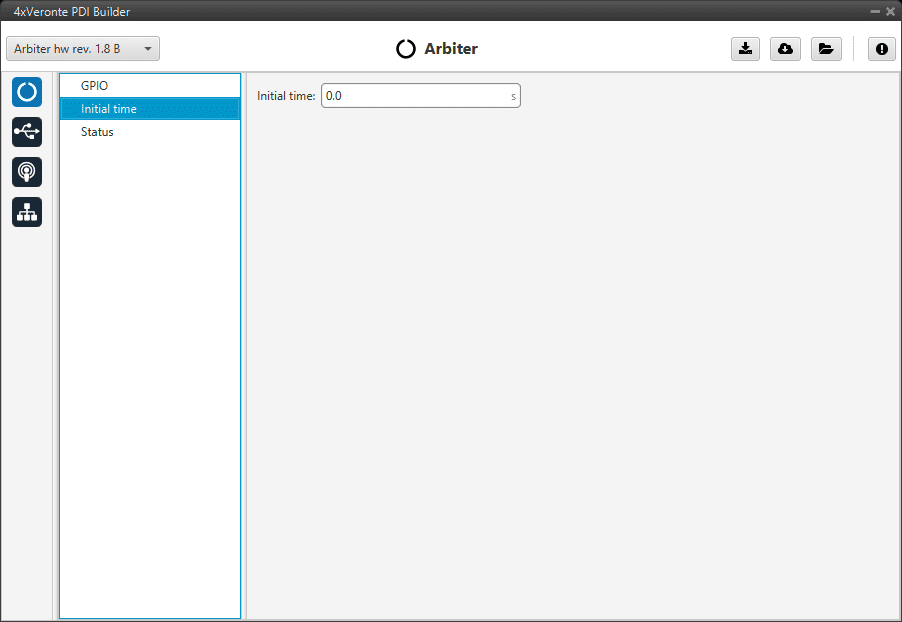
Initial time panel
Status
Enable VCP Status Message: Enables the periodic sending of the status message that Veronte Link uses to recognize an arbiter.
Period: Establishes the desired period to send repeatedly the status message.
Note
VCP is the Veronte Communication Protocol. To know more, read the VCP user manual.
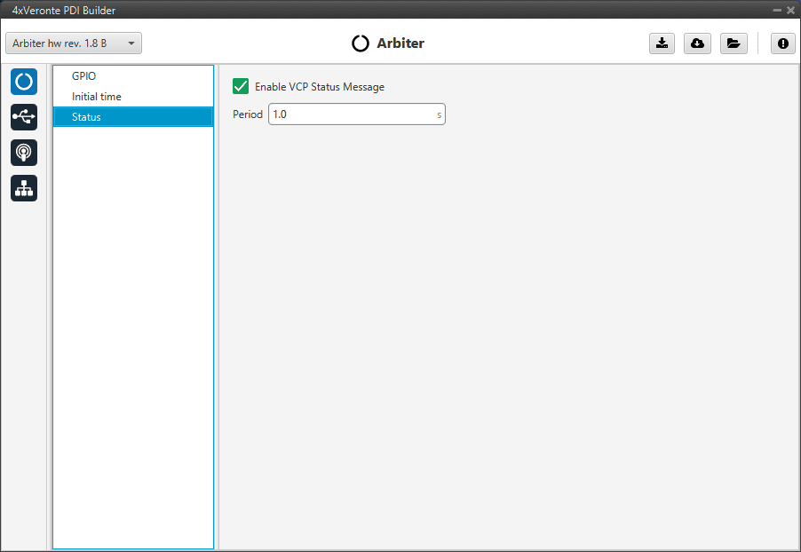
Status panel