Radios
Microhard internal radio
Internal Microhard radios can stablish communication between Veronte Autopilots.
The necessary configuration of Microhard radios for proper communication between them and autopilots 1x is described in the Integration examples -> Microhard internal radio section of the 1x PDI Builder manual.
DTC (Domo Tactical) radio (SOL8SDR-C model)
System Layout
It is possible to operate DTC radios in two different ways, with or without amplifiers.
DTC
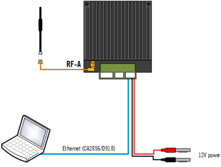
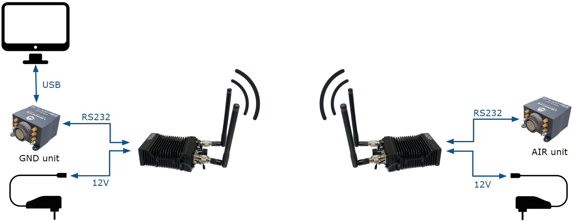
The following image shows the standard connection between DTC radios and Autopilot 1x for operation:
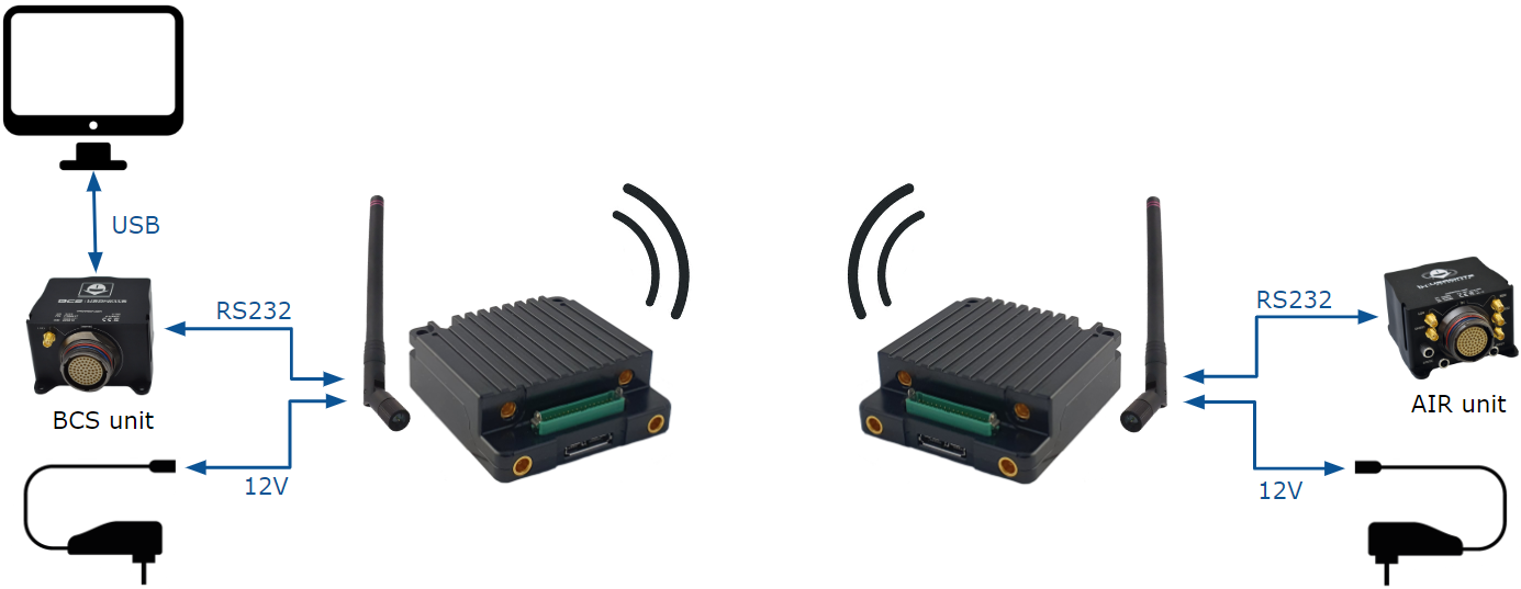
DTC radios and Autopilot 1x operation
DTC + Amplifier
Note
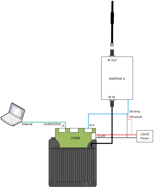
Amplifier information: AMPD5W model, 5W Linear RF Power Amplifier.
The following image shows the standard connection between DTC radios, amplifiers and Autopilot 1x for operation:
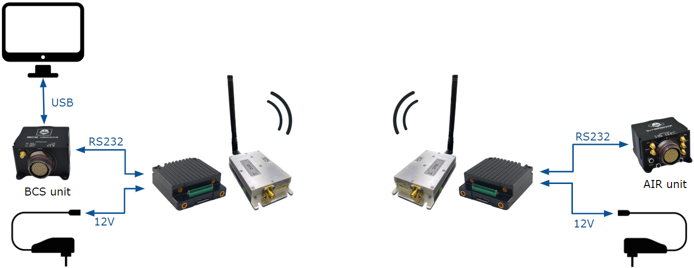
DTC + amplifier radios and 1x operation
Hardware Installation
Depending on the action to be taken, different hardware installations are possible:
To configure a DTC radio it is required to carry out the installation of the ethernet and power connection:

DTC D1804 Gecko breakout PCB
Ethernet
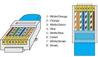
RJ45 pinout T-568B
J4 (Ethernet) - D1804 Gecko breakout PCB
RJ45 Connector (T-568B)
PIN N°
Signal
PIN N°
Signal
Color
1
Ethernet MDIP0
1
TX+
Orange-White
2
Ethernet MDIN0
2
TX-
Orange
3
Ethernet MDIP1
3
RX+
Green-White
4
Ethernet MDIN1
6
RX-
Green
Power supply
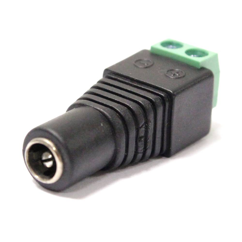
Female DC Power Jack connector
J2 (PWR) - D1804 Gecko breakout PCB
Power connector
PIN N°
Signal
Signal
1
VIN
Power +
2
VIN
3
GND
Power -
4
GND
The full connection should look like this:
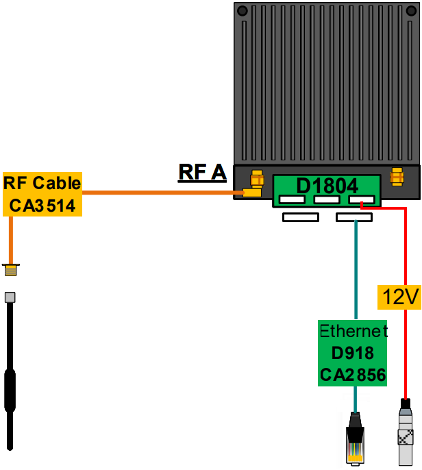
DTC connection - Configuration
To configure a DTC + amplifier radio it is required to carry out the installation of the ethernet, power and amplifier connection:
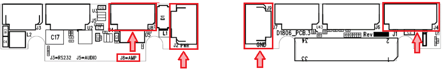
DTC D1806 Gecko active breakout PCB
Ethernet
RJ45 pinout T-568B
J4 (Ethernet) - D1806 Gecko active breakout PCB
RJ45 Connector (T-568B)
PIN N°
Signal
PIN N°
Signal
Color
1
Ethernet MDIP0
1
TX+
Orange-White
2
Ethernet MDIN0
2
TX-
Orange
3
Ethernet MDIP1
3
RX+
Green-White
4
Ethernet MDIN1
6
RX-
Green
Power supply
Female DC Power Jack connector
J2 (PWR) - D1806 Gecko active breakout PCB
Power connector
PIN N°
Signal
Signal
1
VIN
Power +
2
VIN
3
VIN
4
VIN
5
VIN
6
VIN
J9 (GND) - D1806 Gecko active breakout PCB
Power connector
PIN N°
Signal
Signal
1
GND
Power -
2
GND
3
GND
4
GND
5
GND
6
GND
Amplifier

Amplifier AMPD5W
J8 (AMP) - D1806 Gecko active breakout PCB
AMPD5W Connector
PIN N°
Signal
PIN N°
Signal
1
5V_SDA
6
5V_SDA
2
GND
3
GND
4
5V_SCL
5
5V_SCL
7
PA_TDD
7
PA_TDD
J2 (PWR) - D1806 Gecko active breakout PCB
AMPD5W Connector
PIN N°
Signal
PIN N°
Signal
1
VIN
1 & 2
Power +
2
VIN
3
VIN
4
VIN
5
VIN
6
VIN
J9 (GND) - D1806 Gecko active breakout PCB
AMPD5W Connector
PIN N°
Signal
PIN N°
Signal
1
GND
3 & 4
Power -
2
GND
3
GND
4
GND
5
GND
6
GND
The full connection should look like this:

DTC + amplifier connection - Configuration
To connect a DTC radio to a Veronte Autopilot 1x the following installation must be carried out:
As, the connection of a DTC radio to a Veronte Autopilot 1x must be made via RS-232, the connection will be the same as in the configuration case (1), but adding the wiring to RS-232 port.
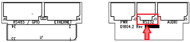
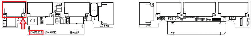
DTC D1804 Gecko breakout PCB - J3 (RS232)
This RS-232 should be connected to the RS-232 of Autopilot 1x Harness.
Harness plug
J3 (RS232) - D1804 Gecko breakout PCB
Harness - Autopilot 1x
PIN N°
Signal
PIN N°
Signal
Color
2
RS232 RX
19
RS 232 TX
White-Pink
1
RS232 TX
20
RS 232 RX
Pink-Brown
3
GND
21
GND
White-Blue
The full connection should look like this:

DTC connection - Veronte Autopilot 1x
To connect a DTC + amplifier radio to a Veronte Autopilot 1x the following installation must be carried out:
As, the connection of a DTC radio to a Veronte Autopilot 1x must be made via RS-232, the connection will be the same as in the configuration case (2), but adding the wiring to RS-232 port.
DTC D1806 Gecko active breakout PCB - J3 (RS232)
This RS-232 should be connected to the RS-232 of Autopilot 1x Harness.
Harness plug
J3 (RS232)- D1806 Gecko active breakout PCB
Harness - Autopilot 1x
PIN N°
Signal
PIN N°
Signal
Color
2
RS232 RX
19
RS 232 TX
White-Pink
1
RS232 TX
20
RS 232 RX
Pink-Brown
3
GND
21
GND
White-Blue
The full connection should look like this:

DTC + amplifier connection - Veronte Autopilot 1x
Caution
It is also possible to calibrate the power output of DTC radios and DTC + amplifier radios.
However, the radios are shipped with a factory calibration, it is strongly recommended to not modify this calibration. If the user wishes to modify it, please contact support@embention.com.
DTC radio configuration
First Steps

DTC ports
DTC without amplifier
Connect to
 an SMP to SMA RF cable (this is the default transmit output).
Connect this SMA RF cable to a 2.4 GHz antenna.
Connect to
 the D1804 Gecko breakout PCB supplied with the unit.
Connect J2 (PWR) of the D1804 PCB to 12V power.
In order to access the web browser control application, connect J4 (ETHERNET) of the D1804 PCB to a PC or network Ethernet port via CA2856 and D918.
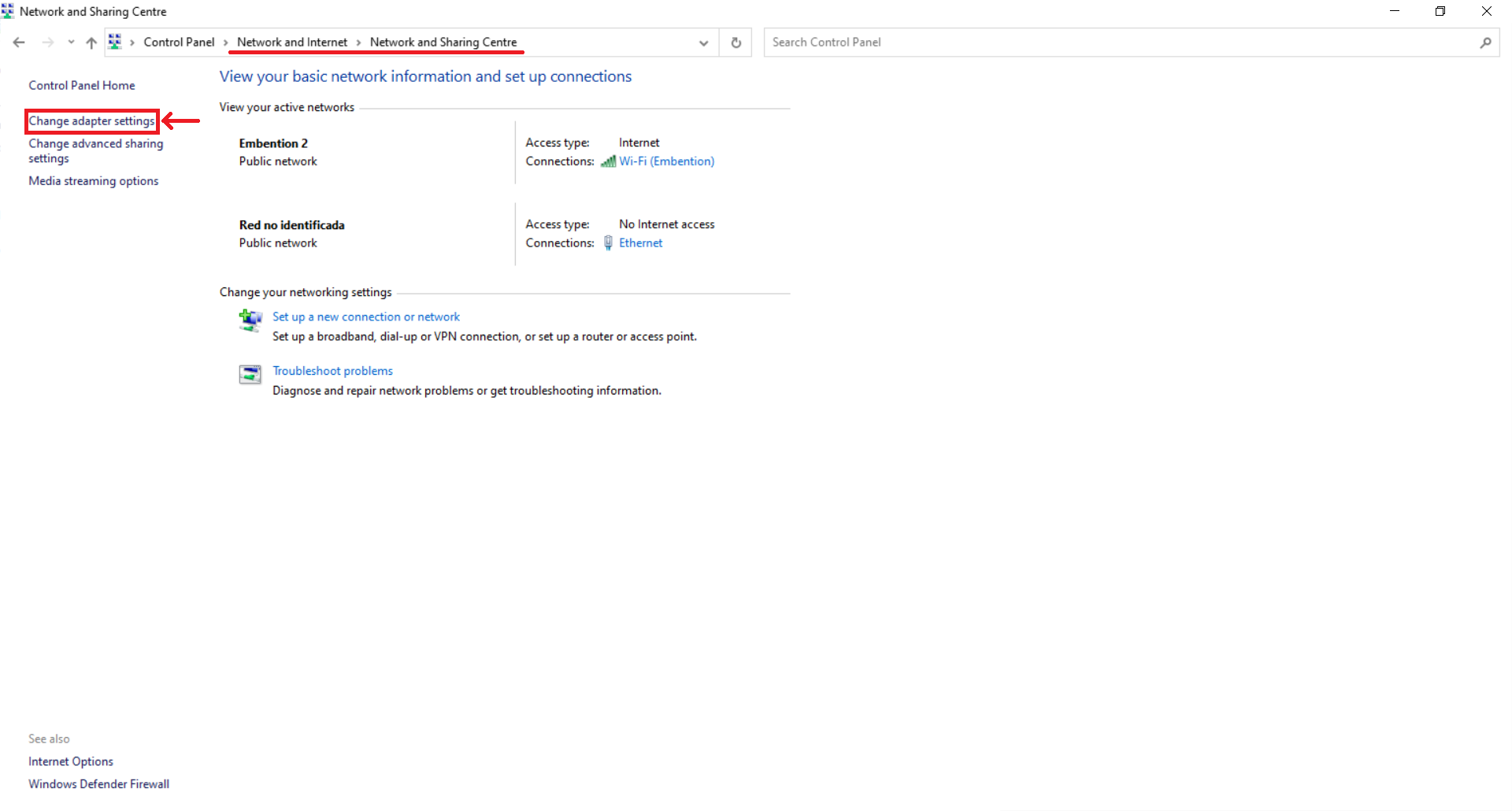
Make sure computer is set to static IP address on same subnet as radio. The following substeps clarify how to set the IP adress:
Open network and sharing menu and click Change adapter settings.

Ethernet connection 1
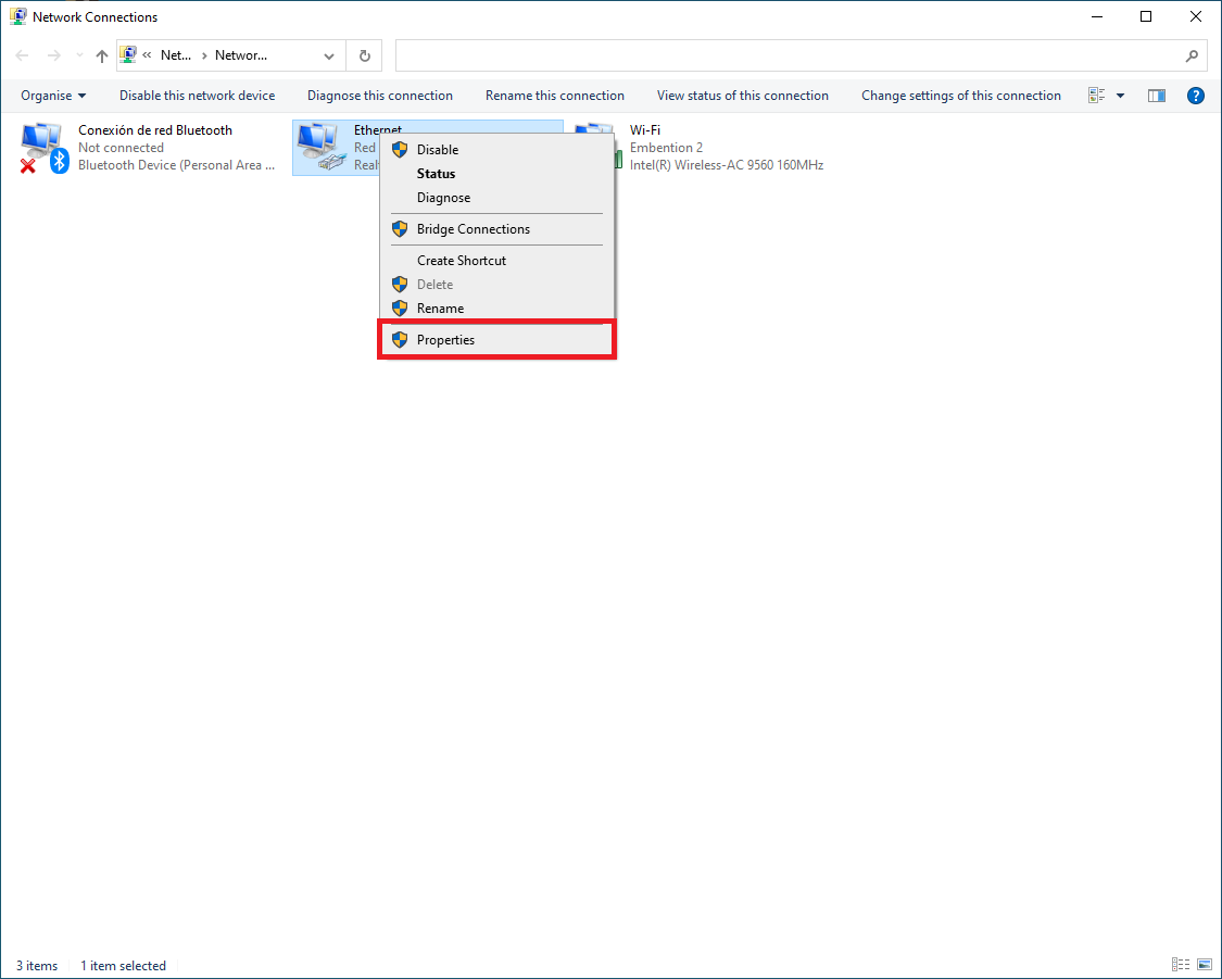
Select Local Area Connection, right click, and select Properties.

Ethernet connection 2
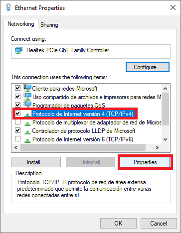
Select IPv4 and click Properties.

Ethernet connection 3
Set IP address to 192.168.8.YY (e.g. if the IP of the radio is 192.168.8.95, set the IP 192.168.8.92) and Subnet mask to 255.255.255.0. Click OK.
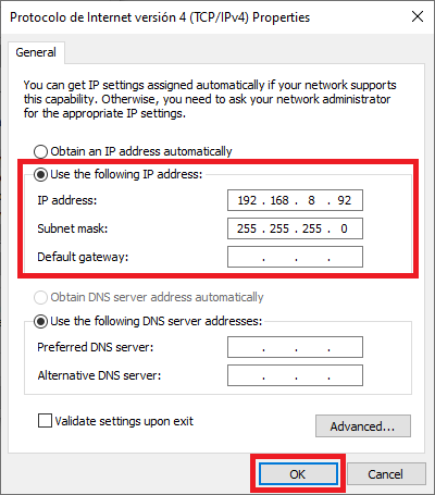
Ethernet connection 4
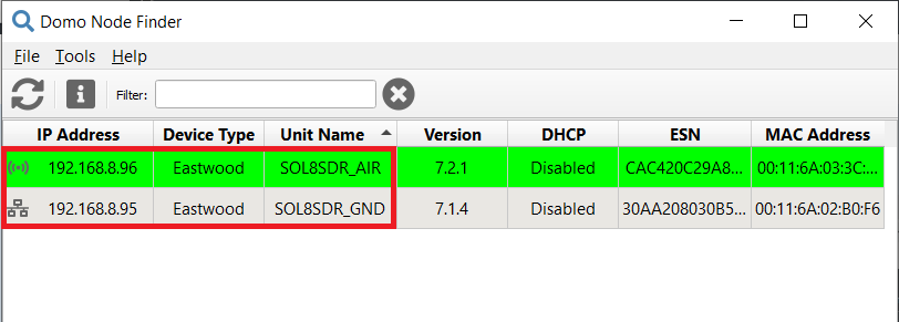
First, it is necessary to have the ‘Domo Node Finder’ software installed.
Open Domo Node Finder and the connected radios will appear here as SOL8SDR.
By default, 0.0.0.0 is the IP address of the radio:
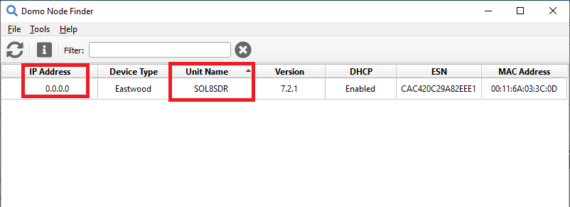
Domo Node Finder - Default IP address
To configure the IP address, right-click the IP address and select Configure Network to disable the DHCP setting and set the following static IP address:

Domo Node Finder - IP address configuration
To confirm the change, click the
 icon to update the IP address.
Domo Node Finder - Configured IP address
Note
This IP address, 192.168.8.95, is related to the radio linked to the BCS unit. For the radio linked to the air unit, the IP address should be 192.168.8.96.
To open the DTC web browser control application, users can right-click the IP address and select WEB Interface (HTTP port 80), double-click on the IP address or enter the IP address of the SOL8SDR-C on the address bar of a web browser.
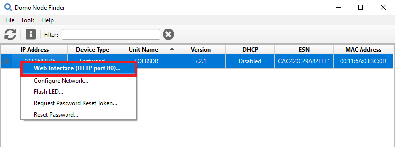
Domo Node Finder - Open Web Browser Application
Note
Although the application should work with any web browser, DTC recommends the use of Internet Explorer, Google Chrome or Firefox.
An authentication required dialogue box will open. Leave the Username blank and enter the Password as Eastwood.

Domo Node Finder - Open Web Browser Application
Click Login and the web browser control application will open.
DTC with amplifier
Connect to
an SMP to SMA RF cable (this is the default transmit output).Connect this SMA RF cable to the amplifier RF IN port.
Connect a 2.4 GHz antenna to the amplifier RF OUT port.
Connect to
the D1806 Gecko active breakout PCB.Connect J4 (ETHERNET) of the D1806 PCB to a PC or network Ethernet port via CA2856 and D918.
Connect J2 (PWR) and J9 (GND) of the D1806 PCB to 12V power.
Connect J8 (AMP) of the D1806 PCB to the control cable from the amplifier connector.
Now the steps to follow are the same as from step 6. of a DTC without amplifier, described above.
Point-to-Point configuration
Basic radio configuration
Once the website has been accessed, follow the steps below which show the parameters that need to be modified for a correct operation and pairing of the radios.
Note
This is an example of the radio configuration linked to a BCS unit.
Note
After making any changes, the application will ‘ask’ to Save or Cancel the changes. An example is shown below:
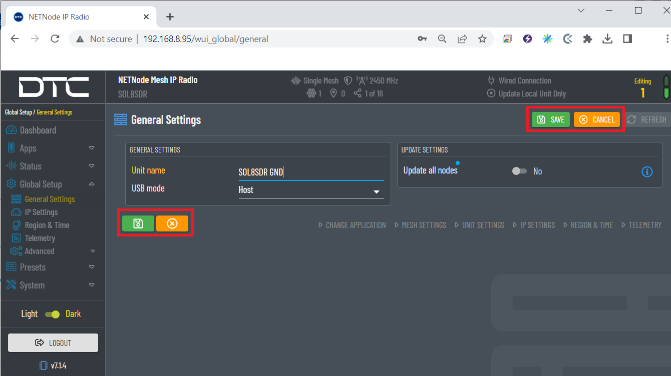
Save or Cancel changes
Global Setup \(\rightarrow\) General Settings: To easily identify each radio in a mesh, the user can rename the radio as desired:
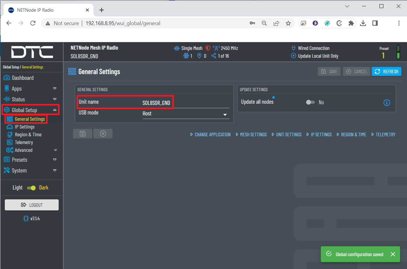
General settings configuration
Note
The radio related to the air unit also has its own personalised name:

General settings air configuration
Presets.
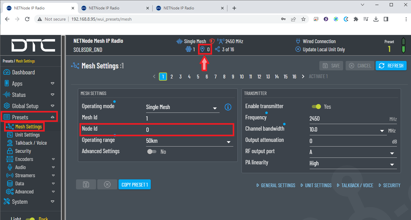
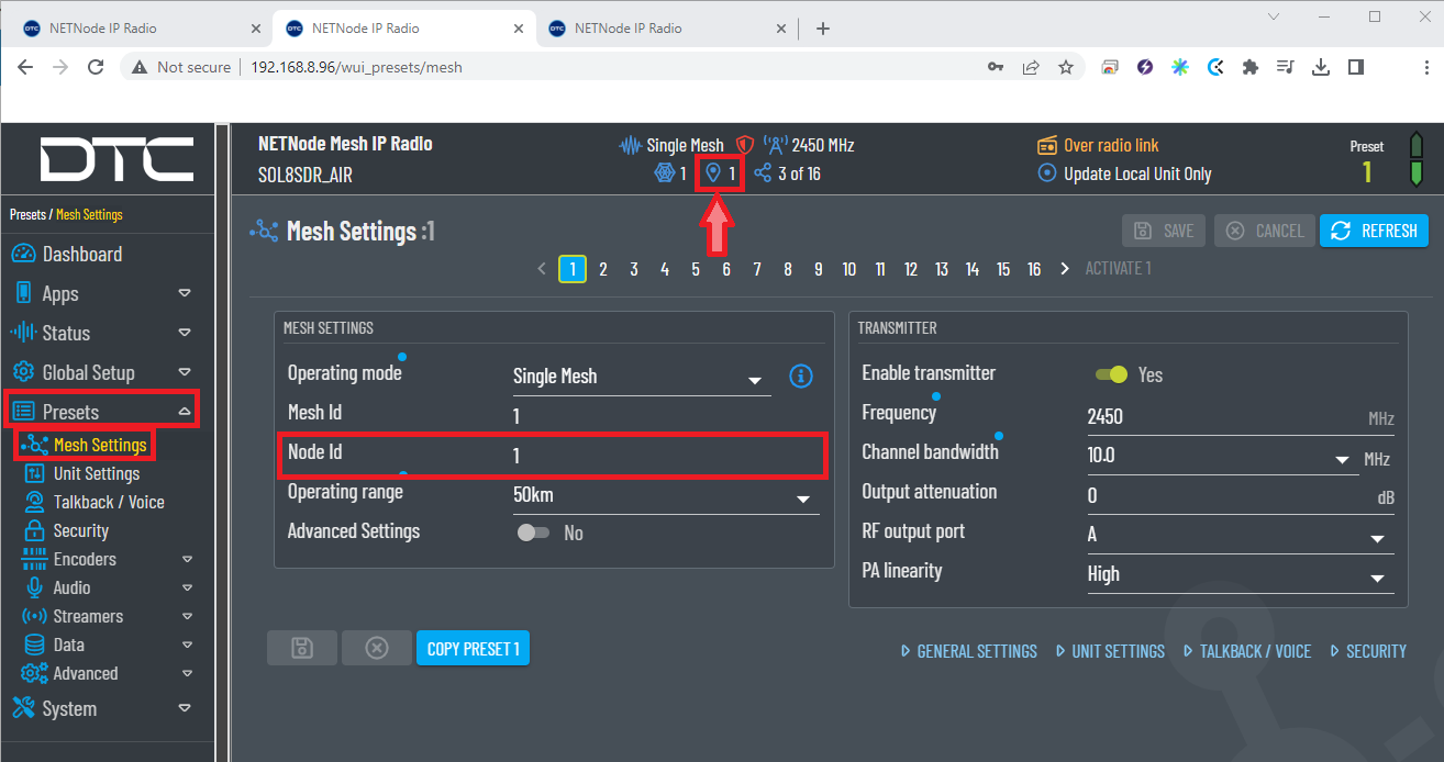
Mesh Settings: Some of the parameters configured in this menu are always displayed at the top of the application.
Caution
It is recommended that software for all devices in a Mesh network should be at the same version to avoid potential compatibility issues.
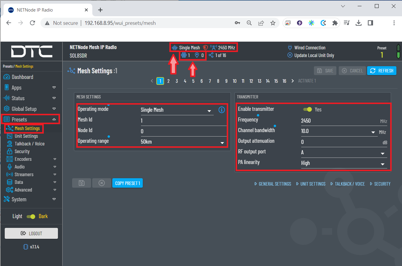
Mesh settings configuration
Operation mode: Select Single Mesh.
Mesh ID: The Mesh ID must be the same on all units in the Mesh network. The Mesh ID tells the unit which network it belongs to, for example, all NETNodes on Mesh ID 1 will communicate with each other. The Mesh ID must be set to a non-zero value.
Node Id: The node ID must be unique in the Mesh network for each device.
Note
A node can automatically reassign its Node ID at power up if it finds a conflict with an existing node.
Operating range: A larger range allows the Mesh network to operate over a bigger distance at the expense of bitrate.
Enable transmitter: Set the checkbox to switch the RF power on.
Frequency: Set the desired transmission frequency. 2450 MHz recommended.
Warning
Be careful when choosing the frequency. The user may see interference with the Wifi frequency band, consult the radio spectrum.
Channel bandwith: Select the desired bandwidth from the drop-down list. Lower bandwidths provide greater range at the expense of data throughput. 10 MHz is recommended.
Output attenuation: The level of attenuation in dB that is applied to the output (from 0 to 32). 0 dB of attenuation is recommended
RF output port: The transmitter has two COFDM antennas, A and B. A is selected as the output antenna by default, but the user can select A or both if required.
PA linearity: High linearity improves the COFDM shoulder performance at the expense of power consumption.
Usually used when working with power amplifiers which must have excellent shoulder performance to operate, or for improved adjacent channel performance.
Warning
To ensure proper communication between the two radios, the radio linked to the air unit must have these same ‘Mesh settings’ except for the Node Id, as each node in the mesh has its own Id (starting with Id 0):
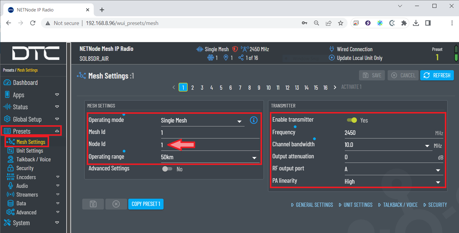
Mesh settings air configuration
Moreover, there are up to 16 different preset configurations that can be setup.
All these settings are made for preset 1, which is highlighted with a blue background in the ‘Mesh settings’ tab to indicate that it is active. In addition, a ‘preset indicator’ with the current present is always displayed at the top right of the application, as shown in the figure below.
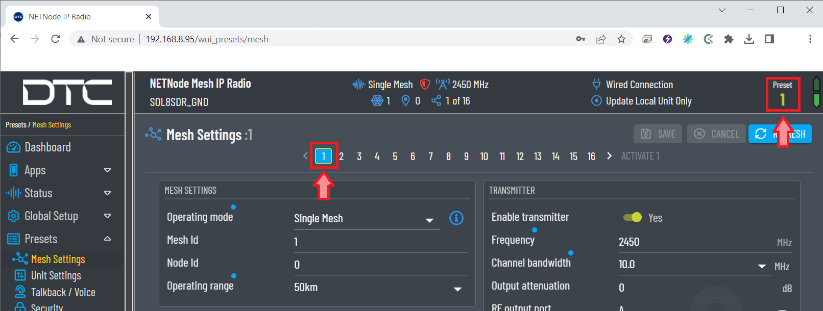
Current preset configuration
Unit Settings:
External Power Enable: There is an external power output which can be used to supply 12VDC (1A) to an external device. This could be a camera, GPS antenna or other device.

Unit settings configuration
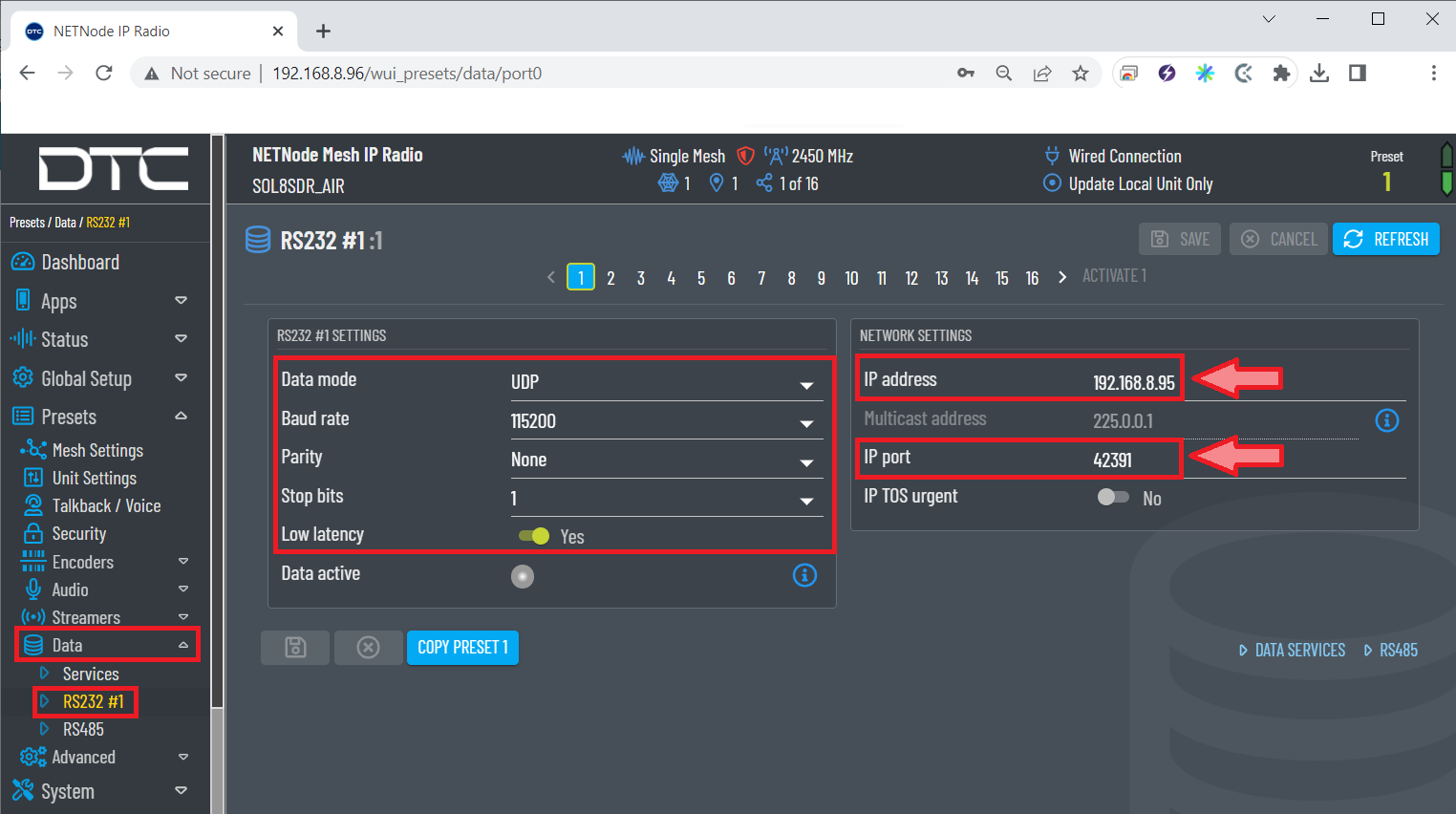
Data \(\rightarrow\) RS232 #1: In this menu the parameters of the RS232 port and the network settings are configured:
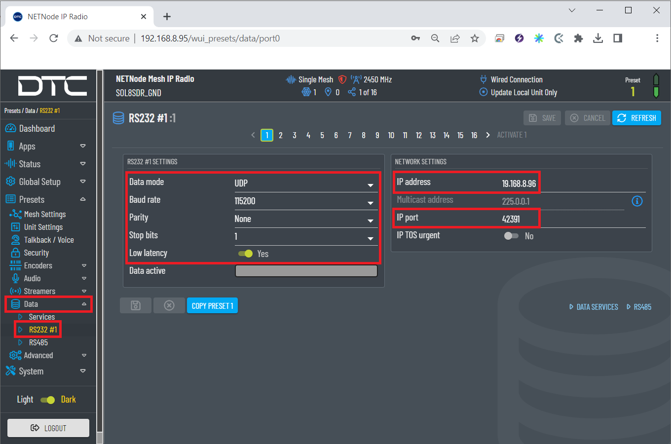
RS232 #1 configuration
Data mode: UDP option is recommended. UDP packets are sent out and the system does not expect a reply. There is no way that the sending device can tell if the data arrived at the destination.
The value of the Baud rate, Parity and Stop Bits parameters must be the same as those configured in the Veronte software:.
Note
The data is assumed to be 8 bits.
Low latency: Low latency will minimise delay at the expense of bitrate, so if set, data tranfer will be less prone to bursts. Yes is recommended.
IP address: This should be the address of the radio receiving the data on the other end of the RS-232. In this case, as the radio connected to the BCS unit is being configured, the IP of the radio linked to the air unit will be set.
IP port: This set an IP port to and from which the data will be transferred. It must be the same for both radios.
Important
For the radio connected to the air unit, the IP address to be configured is the address of the radio linked to the BCS unit.
RS232 #1 air unit configuration
System \(\rightarrow\) Maintenance: This menu allows to import and export radio configurations.

Maintenance configuration
To import a configuration into the radio, it is first necesarry to choose a configuration from the local storage by clicking on the
 icon.
Then, the ‘import button’ will already be available (colored in blue) to click on and consequently import the selected configuration.
An example is shown below:
icon.
Then, the ‘import button’ will already be available (colored in blue) to click on and consequently import the selected configuration.
An example is shown below: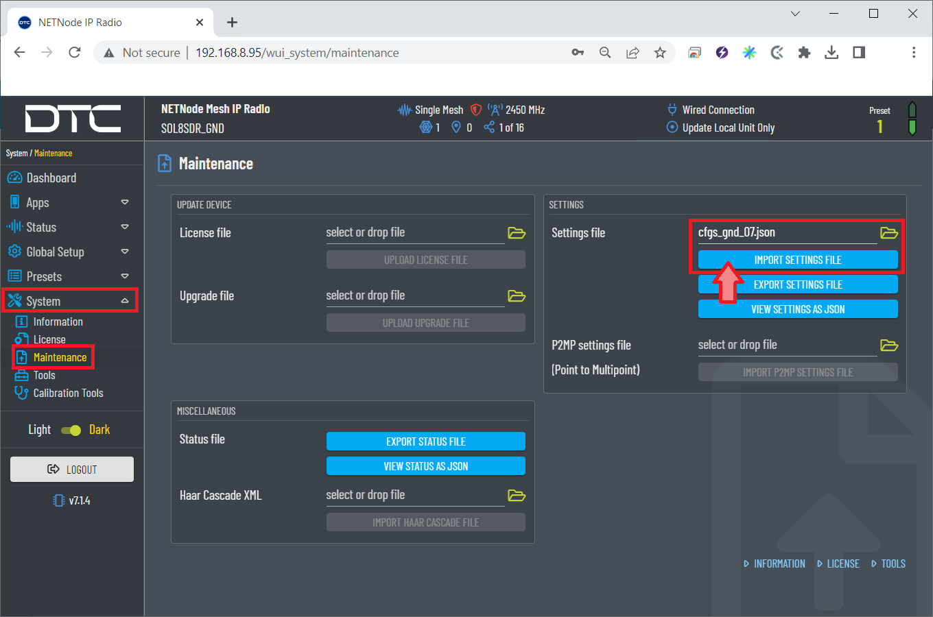
Configuration selected
Paired radios
Once both radios have been configured with these settings, they should be paired. Therefore, if we connect them to the power supply and only one of them to the computer, we can access the Domo Node Finder software or directly the Web Browser control application to check if they are correctly paired.
Domo Node Finder software
When 2 radios are paired, they will both appear here:
Domo Node Finder - Radios paired
As can be seen in the figure above, the connection type of each radio is indicated with different icons:
 icon for the radio that is wiredly connected to the PC.
 icon for the radio that is connected by link.
Web Browser control application
When two radios are paired, this can be seen/checked directly in the ‘Dashboard’ of both radios.

Radios paired - Dashboard
Furthermore, it can be seen that the above figure is related to the radio that is connected by link, as it is indicated at the top of the application with the label Over radio link.
Apps \(\rightarrow\) Tactical Display: Here the user can check the connection and the quality of the signal connection of both radios:

Radios paired - Tactical Display
Map display: The color of the link between nodes indicates the quality of the signal. The colors range from green (reliable link) to red (unreliable link). If no link is displayed, it means that communication has been lost.
TX info: TX info should be selected to check the quality of the signal connection.
Token Tx retries: In a Mesh network, transmission is arbitrated by passing a token between nodes. This tab displays the number of token retries that have been needed for each node. It must be 0 with occasional 1 for a proper communication.
Caution
Higher values will have an undesirable effect on system performance. If problems occur, check for interference and that there is no other Mesh system operating on the same or adjacent frequency.
Point-to-Multipoint configuration
It is possible that the user wants to make a point-to-multipoint radio connection, i.e. there will be one radio sending commands to several radios, so there will be at least 3 radios.
The following is the configuration required for this type of connection.
Radio configuration
The modifications to be made to the basic configuration explained above for the point-to-point application are detailed below.
Note
This example has been made with 3 radios (3 nodes in a mesh).
Presets \(\rightarrow\) Mesh Settings: The Node ID must be different for each node in the mesh.
Mesh settings ground configuration
Mesh settings air configuration

Mesh settings base configuration
In the figures above, the user can see that the node ID is displayed at the top of the application at all times.
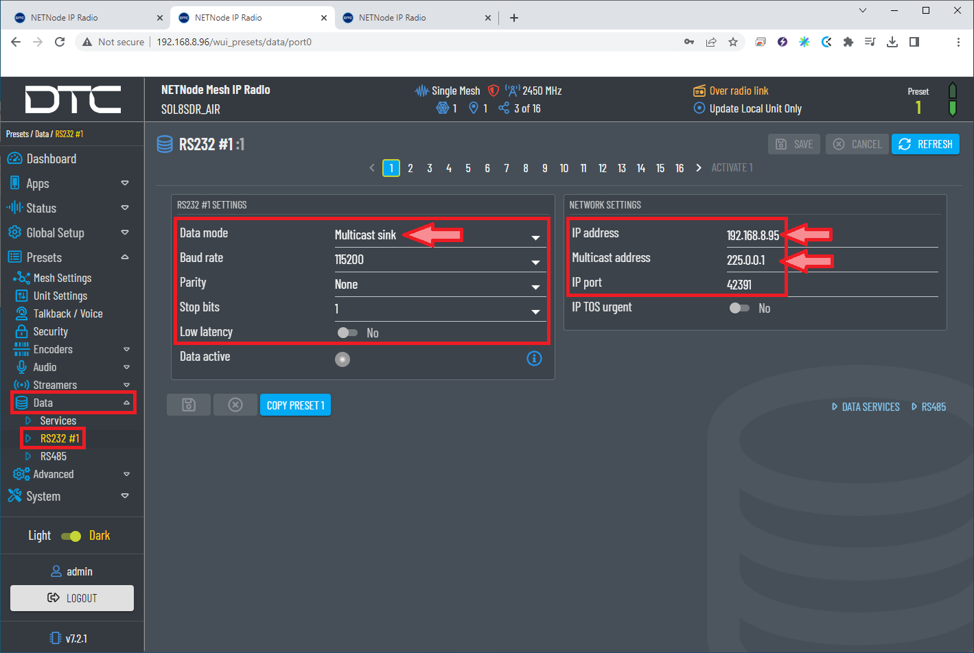
Data \(\rightarrow\) RS232 #1: The Multicast data mode must be configured. This data mode allows a single node to send RS232/RS485 data to multiple nodes in the system. And it also creates a unicast data return channel.
The radio linked to the BCS unit is configured as the ‘Point’ that sends the commands.

RS232 #1 ground configuration
Data mode: Multicast source must be selected.
IP address: To send the data to all receivers the IP address must set to 255.255.255.255.
Multicast address: It must be the same for all radios, avoiding the 244.0.0.X address range.
The address must be different from any multicast streaming and data channels.
Then, the radios linked to the air and base units receive those commands:
RS232 #1 air unit configuration

RS232 #1 base unit configuration
Data mode: Multicast sink must be selected.
IP address: The IP address of the radio linked to the BCS unit is set.
Multicast address: It must be the same for all radios, avoiding the 244.0.0.X address range.
The address must be different from any multicast streaming and data channels.
Paired radios
Once the radios have been configured with these settings, they should be paired. Therefore, if we connect them to the power supply and only one of them to the computer, we can access the Domo Node Finder software or directly the Web Browser control application to check if they are correctly paired.
Domo Node Finder software
When 3 radios are paired, they will appear here:

Domo Node Finder - 3 radios paired
As can be seen in the figure above, there is 1 radio wiredly connected to the PC and 2 radios connected by link.
Web Browser control application
When 3 radios are paired, this can be seen/checked directly in the ‘Dashboard’ of the three radios.

Radios paired - Dashboard
Furthermore, it can be seen that the above figure is related to a radio that is connected by link, as it is indicated at the top of the application with the label Over radio link.
Apps \(\rightarrow\) Tactical Display: Here the user can check the connection and the quality of the signal connection of the radios:
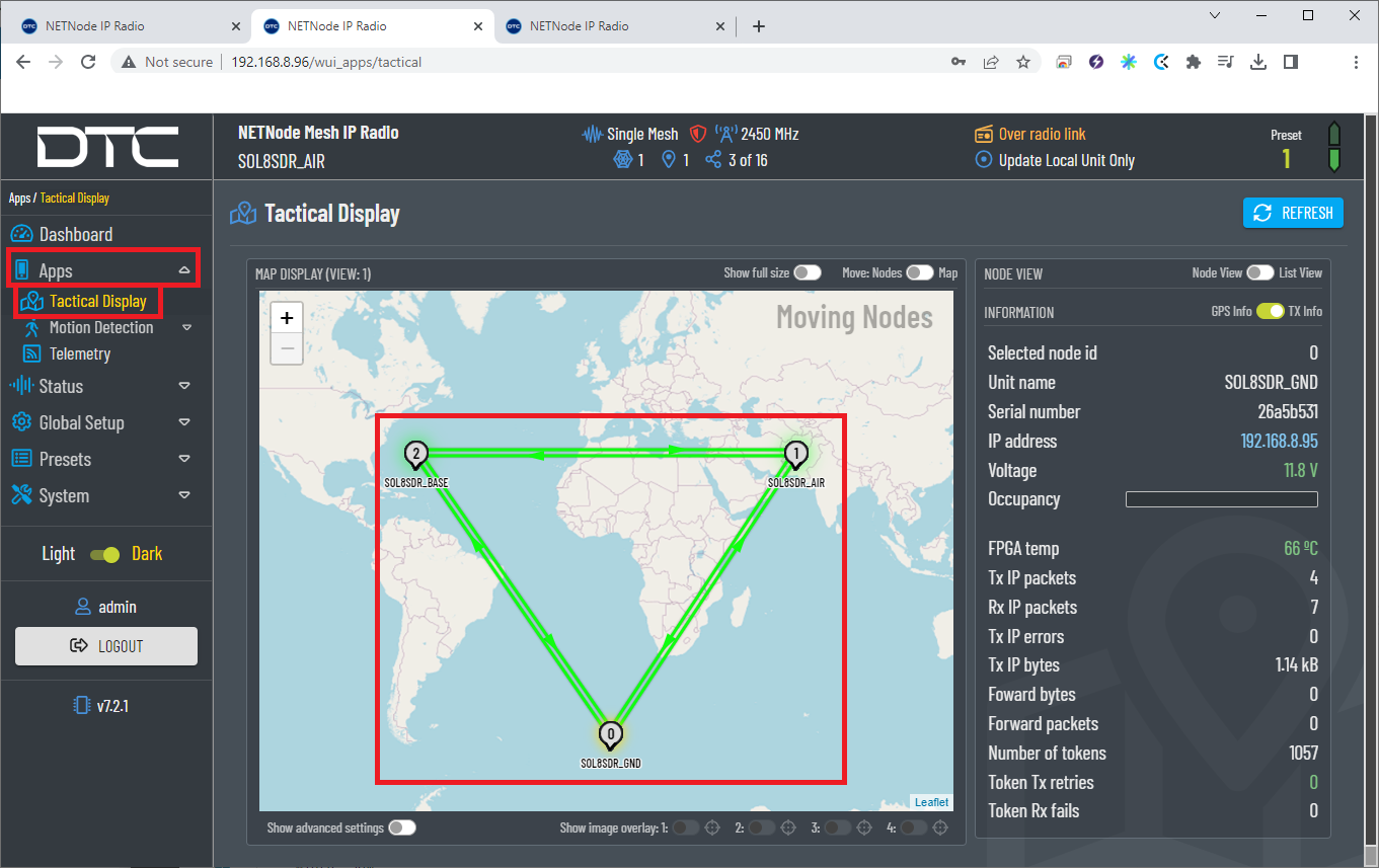
Radios paired - Tactical Display
For more information on the configuration of DTC radios, please refer to the DTC documentation.
DTC radio configuration in autopilot
The necessary configuration of Veronte Autopilot 1x for DTC radios require different applications, according to the software version:
6.8 or higher: use 1x PDI Builder reading its user manual. Go to
Integration examples -> External radios section.
Silvus radio (StreamCaster 4200E model)
System Layout
The following image shows the standard connection between Silvus radios and Autopilot 1x for operation:
Silvus and 1x connection
Hardware Installation
A wiring configuration of the PRI cable connected to the PRI port of the radio is required, in order to connect to the power supply, ethernet and RS-232.
PRI port connector (mounted in radio)
Power supply
Female DC Power Jack connector
PRI port connector - Silvus radio
Power connector
Pin number
Signal
Signal
2
GND IN
Power -
3
VCC IN
Power +
Ethernet
RJ45 pinout T-568B
PRI port connector - Silvus radio
RJ45 Connector (T-568B)
PIN N°
Signal
PIN N°
Signal
Color
4
ETH0_MX2N (RX-)
6
RX-
Green
5
ETH0_MX2P (RX+)
3
RX+
Green-White
6
ETH0_MX1P (TX+)
1
TX+
Orange-White
10
ETH0_MX1N (TX-)
2
TX-
Orange
RS-232
The RS-232 from the PRI cable should be connected to the RS-232 of Autopilot 1x Harness.
Harness plug
PRI port connector - Silvus radio
Harness - Autopilot 1x
PIN N°
Signal
PIN N°
Signal
Color
7
RS232_RXD
19
RS 232 TX
White-Pink
8
RS232_TXD
20
RS 232 RX
Pink-Brown
9
GND
21
GND
White-Blue
Silvus radio configuration
This section shows a basic configuration of the Silvus radio.
First Steps
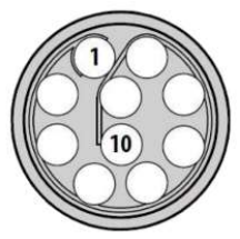
Connect antennas (or attenuators) with male TNC ends to 2 RF ports.
Connect power supply to power port on PRI cable.
Connect non-forked female side of PRI cable to radio’s PRI port.

Silvus connectors
When looking at the rotary multi position switch from the top, pull the knob towards you while rotating the knob towards the 1 position. This turns radio on. LED indicator will turn to fix red.
In order to access the StreamScape graphical user interface (GUI), connect Ethernet (RJ45) connector of PRI cable to Ethernet port of laptop/computer.
Make sure computer is set to static IP address on same subnet as radio. The following substeps clarify how to set the IP adress:
Open network and sharing menu and click Change adapter settings.
Ethernet connection 1
Select Local Area Connection, right click, and select Properties.
Ethernet connection 2
Select IPv4 and click Properties.
Ethernet connection 3
Set IP address to 172.20.XX.YY (e.g. if the IP of the radio is 172.20.178.203, set the IP 172.20.178.200) and Subnet mask to 255.255.0.0. Click OK.
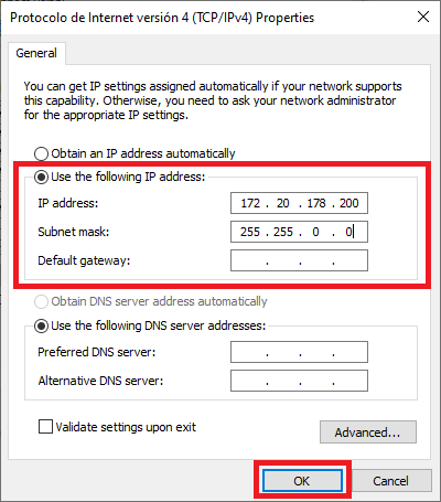
Ethernet connection 4
Wait for LED indicator to turn to blinking green.
Access StreamScape GUI in web browser. To access, enter IP address of radio into web browser and press enter.
Note
Latest version of Firefox or Google Chrome are preferred. Internet Explorer or others are not recommended.
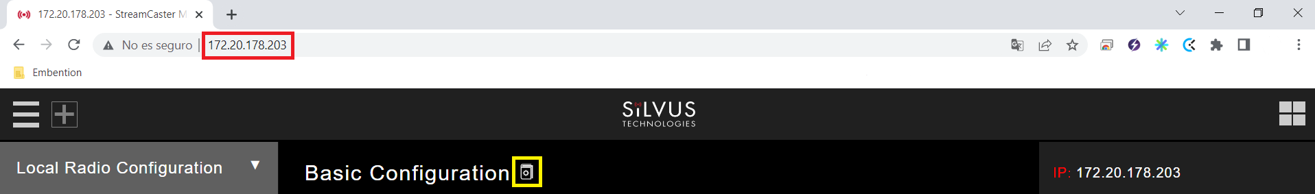
Silvus initial menu
User manual can be accessed by clicking the book icon in the GUI (Next to Basic Configuration in the previous screenshot).
Basic radio configuration
Once the website has been accessed, follow the steps below which show the parameters that need to be modified for correct operation and pairing of the radios.
Note
This is an example of the radio configuration linked to a 1x air unit.
Note
After making changes to each window, it is important to click on “Save and apply”.
Basic Configuration.
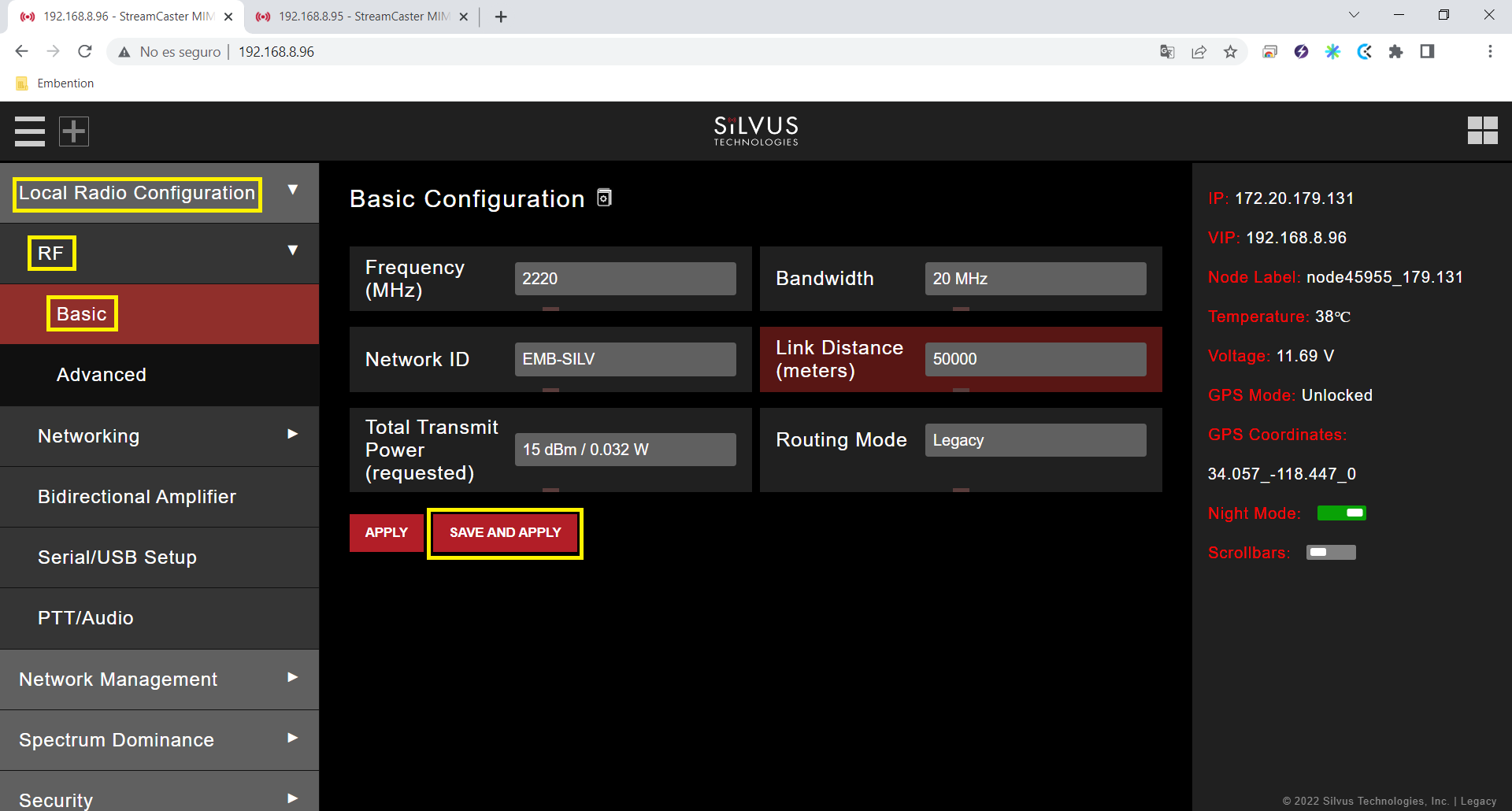
Basic configuration panel
Frequency (MHZ): This defines the frequency of the signal. There is a drop-down menu for frequency selection. We recommend 2220 MHz.
Warning
Be careful when choosing the frequency. The user may see interference with the Wifi frequency band, consult the radio spectrum.
Bandwith: This defines the RF bandwidth of the signal. Default value.
Network ID: Network ID allows for clusters of radios to operate in the same channel, but remain independent. A radio with a given Network ID will only communicate with other radios with the same Network ID.
Link Distance (meters): Set to an approximate maximum distance between any two nodes in meters. It is important to set the link distance to allow enough time for packets to propagate over the air. It is recommended to set the link distance 10-15% greater than the actual maximum distance.
Total Transmit Power (requested): This defines the total power of the signal (power is divided equally between the radio antenna ports). Set the appropriate power for each application. The power that has been set is small, as it is sufficient for our tests.
Routing Mode: As Large Network mode requires a license and is not available outside USA, we set Legacy mode.
Advanced configuration.
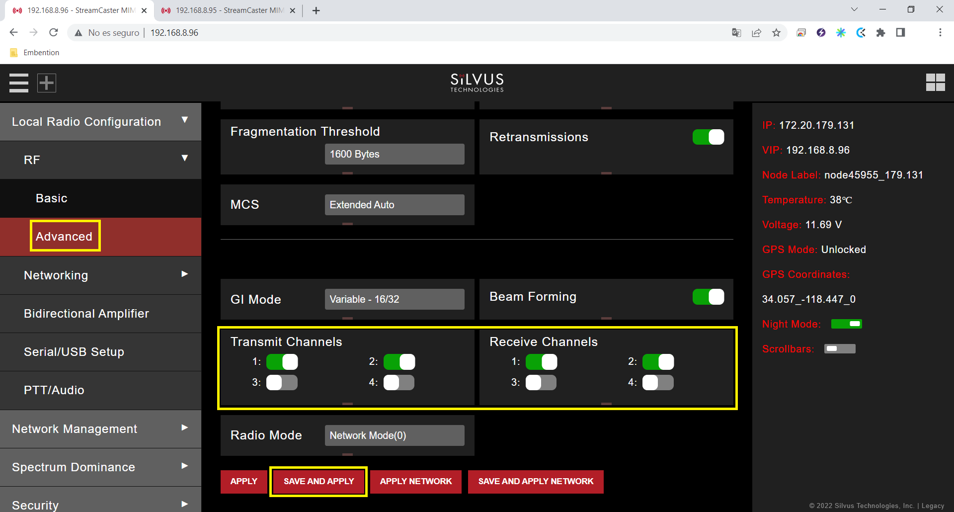
Advanced configuration panel
Transmit/Receive Channels: Allows user to enable or disable each channel on the radio for TX/RX (each RF port is a channel). We have enabled both channels.
Networking. Multicast.
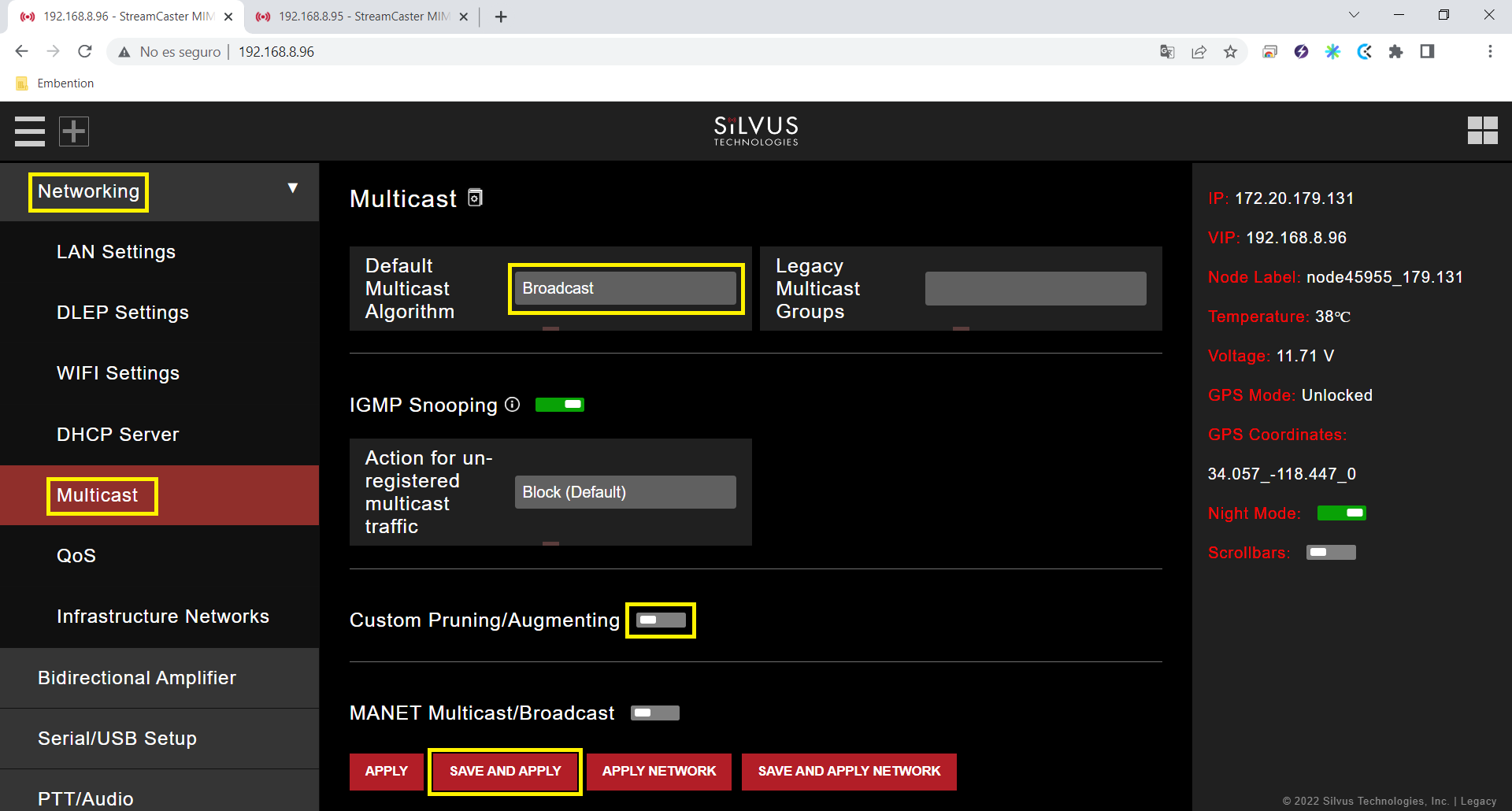
Multicast panel
Default Multicast Algorithm: Broadcast.
Custom Pruning/Augmenting: Disable.
Serial/USB Setup

RS-232 settings
Serial Port Setup: RS-232.
RS-232 Serial Port Settings
The value of the Baudrate, Data Bits, Parity and Stop Bits parameters must be the same as those configured in the Veronte software:.
Software Flow Control: Disable.
Transport Protocol: We recommend UDP. If no data loss can be tolerated, change this setting to TCP on the radio corresponding to the 1x air unit.
Peer IP: This should be the IP address of the radio on the other end of the RS-232. In this example, we must set the IP address of the radio linked to the GND unit.
Note
Both radios (the one connected to the GND unit and the one connected to the AIR unit) have the same configuration except for the Peer IP.
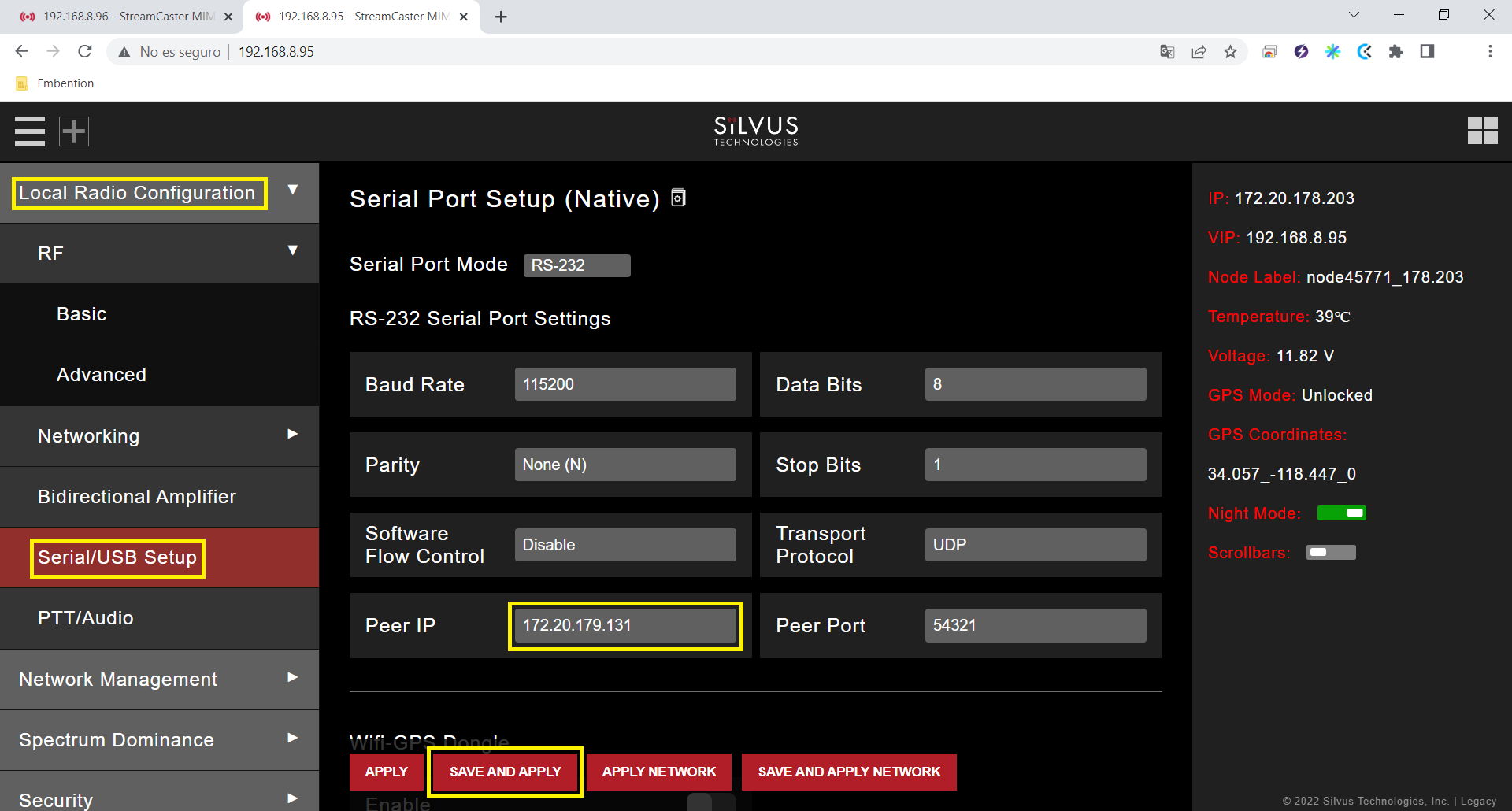
Peer IP in radio linked to the GND unit
In addition to these settings, different configurations can be stored in the same radio, on the Multi-Position Switch panel. The user can select the one that will work, with the radio’s switch position.
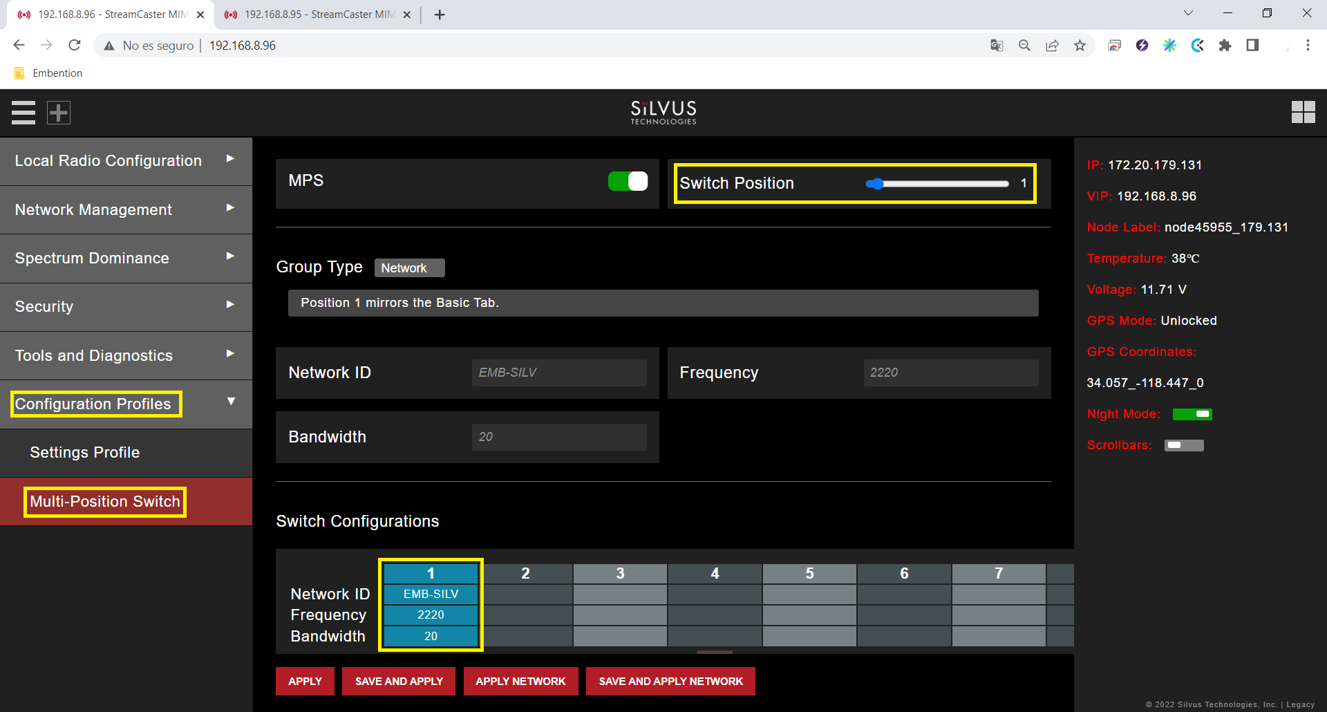
Multi-Position Switch panel
In this example only one configuration has been created.
With the above settings the configuration is finished. Furthermore, this configuration can be saved and downloaded in the Settings Profile window of the Configuration Profiles section.
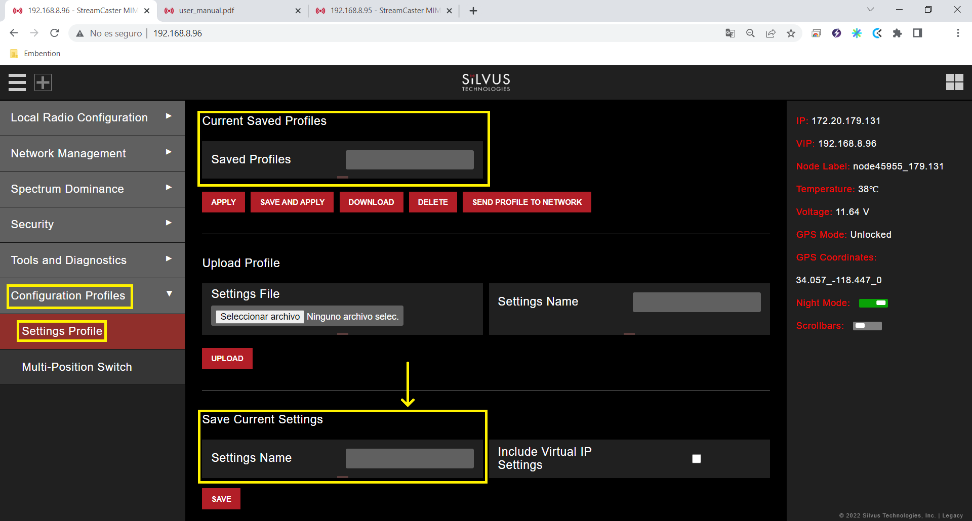
Settings Profile panel
Before downloading the configuration, it is necessary to save it.

Save settings
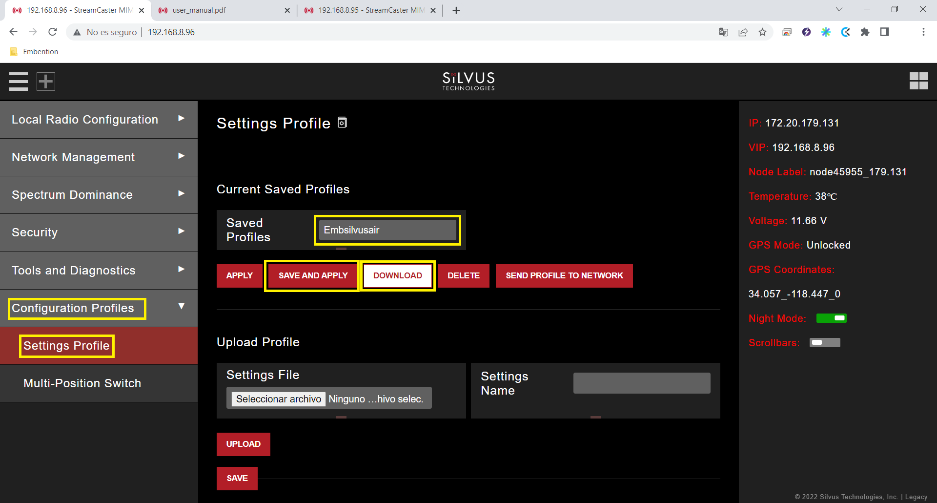
Download settings
After configuring both radios with these settings they should be paired. Therefore, if we connect them to the power supply, when we switch them on, the LED will turn from fix red to fix green, this indicates that it is connected to at least one radio. Also, if we connect only one of them to the computer, we can access the StreamScape GUI of both.
And, in the Network Topology window of the Network Management section, we can see the link between them.
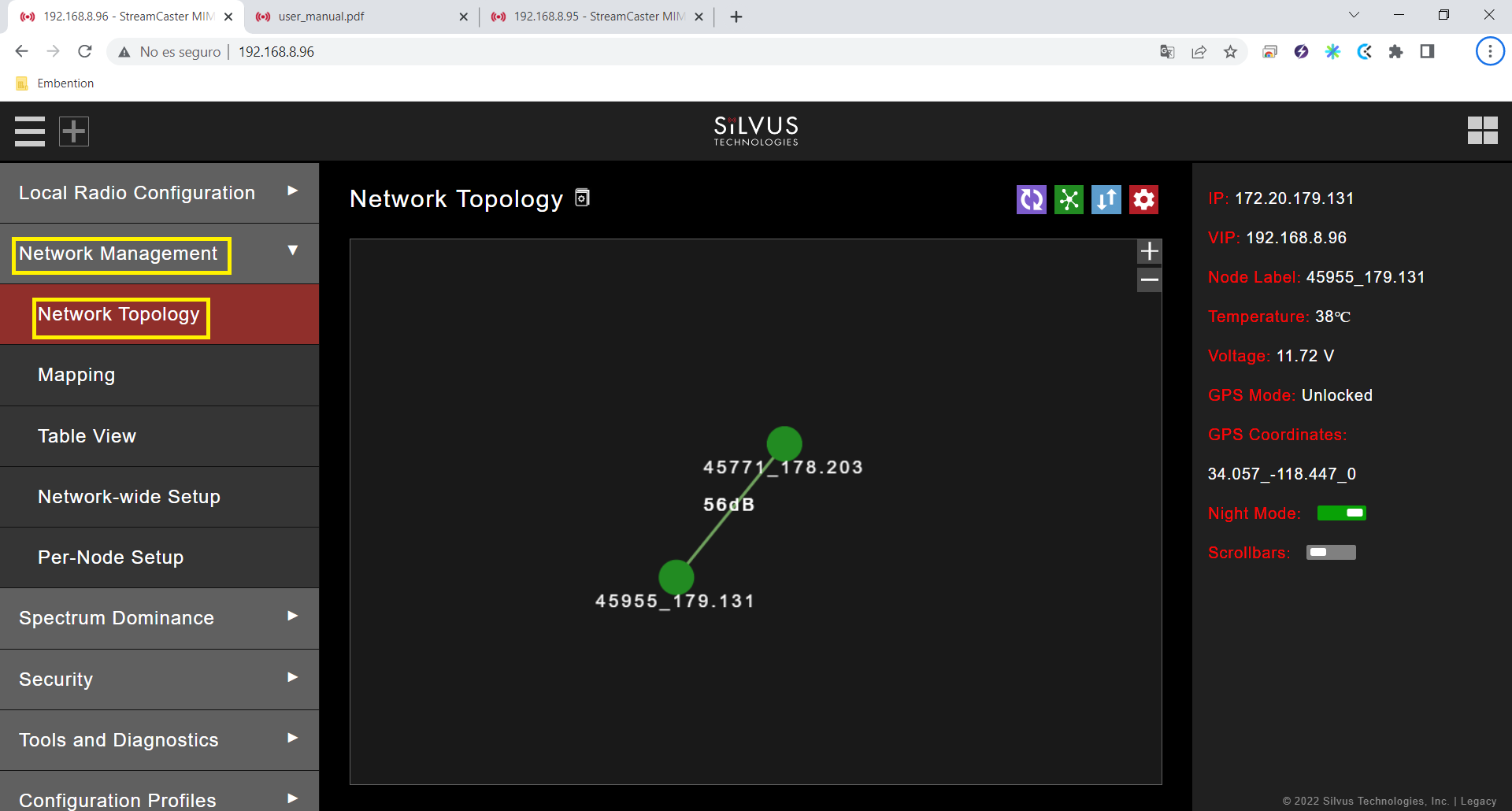
Connection between radios
Silvus radio configuration in autopilot
The necessary configuration of Veronte Autopilot 1x for Silvus radios require different applications, according to the software version:
6.8 or higher: use 1x PDI Builder reading its user manual. Go to
Integration examples -> External radios section.
6.4 or lower: use Veronte Pipe reading the Veronte Autopilot manual. Go to
Veronte Autopilot -> Silvus Radio Configuration.