Hardware Installation
Mechanical assembly
Veronte Autopilot 1x is manufactured using an anodized aluminium enclosure with enhanced EMI shielding and IP protection. A high reliability connector is also provided. The total weight is 190 g for enclosure version and 90 g for OEM.
Dimensions
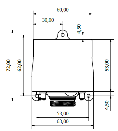
Veronte Autopilot 1x dimensions
M3 screws are recommended for mounting. In saline environments such as coastal and oceanic, the screw material must be stainless steel.
Pressure lines
Pressure Intake |
|---|
Pressure intakes must be located in order to prevent clogging. |
Never install pressure intakes on the propeller flow. |
Design pressure tubing path in order to avoid tube constriction. |
Static Pressure |
|---|
It is not recommended to use inside fuselage pressure if it is not properly vented. |
Pitot Tube |
|---|
Pitot tube must be installed facing the airflow. |
It is recommended to install it near the aircraft’s x axis in order to avoid false measures during manoeuvres. |
For low-speed aircraft it is recommended at least 6.3mm tubes to prevent any rain obstruction. |
Note
In case of not using an input air connector, it is recommended to remove its corresponding nut. Vibrations may move and damage intake connectors with a nut that is not fixed with a tube.
Location
The location of Veronte Autopilot 1x has no restrictions. It is only required to configure its relative position respect to the centre of mass of the aircraft and the GNSS antenna. The configuration of the location of Veronte Autopilot 1x can be easily configured reading the manual of the corresponding software.
Orientation
The orientation of Veronte Autopilot 1x has no restrictions either. It is only needed to configure axes with respect to the aircraft body axes by means of a rotation matrix or a set of correspondences between axes. The configuration of the orientation can be easily configured reading the manual of the corresponding software.
Axes are printed on the Autopilot 1x box. Aircraft coordinates are defined by the standard aeronautical conventions (see image below).
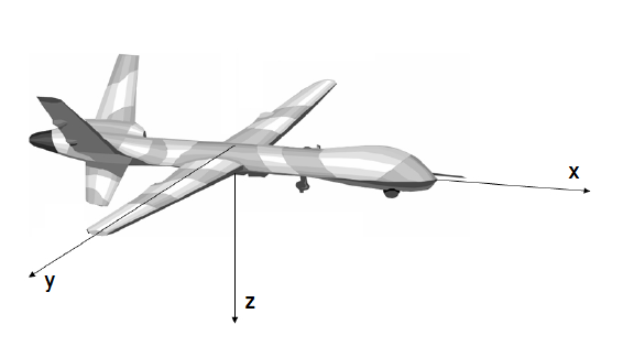
Aircraft Coordinates (Standard Aeronautical Convention)
Vibration Isolation
Although Veronte Autopilot 1x rejects noise and high-frequency modes of vibration with electronic filters and internal mechanical filters, there might be situations where external isolation components might be needed.
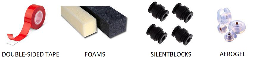
Autopilot 1x can be mounted in different ways in order to reject the airframe vibration. The simplest way could be achieved by just using double-sided tape on the bottom side of Veronte. Other ways may use some external structure which could be rigidly attached to the airframe and softly attached to Veronte (e.g. foam, silent blocks, aerogel, etc).
The user should take into account that wiring should be loose enough so vibrations may not be transmitted to Veronte Autopilot 1x.
In cases where mechanical isolation is not viable, it is possible to use soft engine mounts. It is also recommended when there are other sensible payloads like video cameras or for high vibration engines.
Antenna Integration
The system uses different kinds of antennas to operate that must be installed on the airframe. Here you can find some advice for obtaining the best performance and for avoiding antenna interferences.
Antenna Installation |
|---|
Maximize separation between antennas as much as possible. |
Keep them far away from alternators or other interference generators. |
Always isolate antenna ground panel from the aircraft structure. |
Make sure the antenna is securely mounted. |
Always use high-quality RF wires minimising the wire length. |
Always follow the antenna manufacturer manual. |
SSMA connections shall be tightened applying 1 Nm of torque |
For all-weather aircraft, insert SSMA lightning protectors. |
GNSS Antenna |
|---|
Antenna top side must point the sky. |
Install it on a top surface with direct sky view. |
Never place metallic / carbon parts or wires above the antenna. |
It is recommended to install it on a small ground plane. |
For all-weather aircraft, insert SSMA lightning protectors. |
Electrical
Power
Veronte can use unregulated DC (6.5V to 36V). Pins used for power and ground are the same for both Ground and Air configurations.
LiPo batteries between 2S and 8S can be used without regulation needs. Remaining battery level can be controlled by the internal voltage sensor and by configuring the voltage warnings on the Veronte software.
For higher voltage installations, voltage regulators must be used. For dimensioning voltage regulators take into account that a blocked servo can activate regulator thermal protection.
Warning
Caution!! Power Veronte out of the given range can cause irreversible damage to the system. Please read carefully the manual before powering the system.
Veronte and servos can be powered by the same or different batteries. In case of having more than one battery on the system, a single point ground union is needed to ensure a good performance. The ground signal should be isolated from other noisy ground references (e.g. engines). If all grounds need to be connected, the connection should be made on the negative pole of the battery.
It is recommendable to use independent switches for autopilot and motor/actuators. During the system initialization, the PWM signal will be set to low level (0V), please make sure that actuators/motor connected support this behaviour before installing a single switch for the whole system.
Veronte Autopilot 1x I/O Signals
68 pin connector for Autopilot 1x (frontal view)
Pin |
Signal |
Type |
Comments |
|---|---|---|---|
1 |
I/O1 |
I/O |
PWM / Digital I/O signal (0-3.3V). Protected against ESD and short circuit |
2 |
I/O2 |
I/O |
PWM / Digital I/O signal (0-3.3V). Protected against ESD and short circuit |
3 |
I/O3 |
I/O |
PWM / Digital I/O signal (0-3.3V). Protected against ESD and short circuit |
4 |
I/O4 |
I/O |
PWM / Digital I/O signal (0-3.3V). Protected against ESD and short circuit |
5 |
I/O5 |
I/O |
PWM / Digital I/O signal (0-3.3V). Protected against ESD and short circuit |
6 |
I/O6 |
I/O |
PWM / Digital I/O signal (0-3.3V). Protected against ESD and short circuit |
7 |
I/O7 |
I/O |
PWM / Digital I/O signal (0-3.3V). Protected against ESD and short circuit |
8 |
I/O8 |
I/O |
PWM / Digital I/O signal (0-3.3V). Protected against ESD and short circuit |
9 |
GND |
GROUND |
Ground signal for actuators 1-8 |
10 |
I/O9 |
I/O |
PWM / Digital I/O signal (0-3.3V). Protected against ESD and short circuit |
11 |
I/O10 |
I/O |
PWM / Digital I/O signal (0-3.3V). Protected against ESD and short circuit |
12 |
I/O11 |
I/O |
PWM / Digital I/O signal (0-3.3V). Protected against ESD and short circuit |
13 |
I/O12 |
I/O |
PWM / Digital I/O signal (0-3.3V). Protected against ESD and short circuit |
14 |
I/O13 |
I/O |
PWM / Digital I/O signal (0-3.3V). Protected against ESD and short circuit |
15 |
I/O14 |
I/O |
PWM / Digital I/O signal (0-3.3V). Protected against ESD and short circuit |
16 |
I/O15 |
I/O |
PWM / Digital I/O signal (0-3.3V). Protected against ESD and short circuit |
17 |
I/O16 |
I/O |
PWM / Digital I/O signal (0-3.3V). Protected against ESD and short circuit |
18 |
GND |
GROUND |
Ground signal for actuators 9-16 |
19 |
RS 232 TX |
Output |
RS 232 Output (-13.2V to 13.2V Max, -5.4V to 5.4V Typical). Protected against ESD and short circuit |
20 |
RS 232 RX |
Input |
RS 232 Input (-25V to 25V Max, -0.6V Low and 2.4V High Threshold). Protected against ESD and short circuit |
21 |
GND |
GROUND |
Ground signal for buses |
22 |
Analog 4 |
Input Analog |
Input 0-3V. Protected against ESD and short circuit |
23 |
Analog 5 |
Input Analog |
Input 0-3V. Protected against ESD and short circuit |
24 |
GND |
GROUND |
Ground signal for buses |
25 |
CanA P |
I/O |
CANbus interface, up to 1Mbps (2.3V Typical, 1.2V-2.3V Differential). Protected against ESD |
26 |
CanA N |
I/O |
Twisted pair with a 120Ω Zo recommended (2.3V Typical, 1.2V-2.3V Differential). Protected against ESD |
27 |
GND |
GROUND |
Ground signal for buses |
28 |
CANB_P |
I/O |
CANbus interface. It supports data rates up to 1 Mbps. Protected against ESD |
29 |
CANB_N |
I/O |
Twisted pair with a 120 Ω Zo recommended. Protected against ESD |
30 |
GND |
GROUND |
Ground signal for buses |
31 |
I2C_CLK |
Output |
Clk line for I2C bus (0.3V to 3.3V). Protected against ESD and short circuit |
32 |
I2C_DATA |
I/O |
Data line for I2C bus (0.3V to 3.3V). Protected against ESD and short circuit |
33 |
GND |
GROUND |
Ground for 3.3V power supply |
34 |
3.3V |
POWER |
3.3V - 100mA power supply. Protected against ESD short circuit with 100mA resettable fuse |
35 |
GND |
GROUND |
Ground for 5V power supply |
36 |
5V |
POWER |
5V – 100mA power supply. Protected against ESD short circuit with 100mA resettable fuse |
37 |
GND |
GROUND |
Ground for analog signals |
38 |
ANALOG_1 |
Input |
Analog input 0-3V. Protected against ESD and short circuit |
39 |
ANALOG_2 |
Input |
Analog input 0-3V. Protected against ESD and short circuit |
40 |
ANALOG_3 |
Input |
Analog input 0-3V. Protected against ESD and short circuit |
41 |
GND |
GROUND |
Ground for FTS signals |
42 |
FTS1_OUT |
Output |
Deadman signal from comicro. Protected against ESD and short circuit |
43 |
FTS2_OUT |
Output |
!SystemOK Bit. Protected against ESD and short circuit |
44 |
GND |
GROUND |
Ground signal for safety buses |
45 |
V_ARB_TX |
Output |
Veronte comicro UART output to activate safety mechanism. Protected against ESD and short circuit |
46 |
V_ARB_RX |
Input |
Veronte comicro UART output to activate safety mechanism. Protected against ESD and short circuit |
47 |
GND |
GROUND |
Ground signal comicro power supply |
48 |
V_ARB_VCC |
POWER |
Veronte comicro power (6.5V to 36V). Protected against ESD and reverse polarity |
49 |
FTS3_OUT_MPU |
Output |
MPU alive voting signal, to use with 4xVeronte. It is a Square Wave at [100,125] Hz. Protected against ESD and short circuit |
50 |
OUT_RS485_P |
Output |
Non-inverted output from RS485 bus (-7V to 12V Max, -2.3V to 2.3V Typical). Protected against ESD and short circuit |
51 |
OUT_RS485_N |
Output |
Inverted output from RS485 bus (-7V to 12V Max, -2.3V to 2.3V Typical). Protected against ESD and short circuit |
52 |
IN_RS845_N |
Input |
Inverted input from RS485 bus (-7V to 12V Max, -2.3V to 2.3V Typical). Protected against ESD and short circuit |
53 |
IN_RS845_P |
Input |
Non-inverted output from RS485 bus (-7V to 12V Max, -2.3V to 2.3V Typical). Protected against ESD and short circuit |
54 |
RS-485_GND |
GND |
Ground for RS-485 bus |
55 |
EQEP_A |
I/O |
DIGITAL output / DIGITAL input / Encoder quadrature input A (0-3.3V). Protected against ESD and short circuit |
56 |
EQEP_B |
I/O |
DIGITAL output / DIGITAL input / Encoder quadrature input B (0-3.3V). Protected against ESD and short circuit WARNING!: Only use it as digital I/O with Veronte units of Hardware version 4.5 or lower |
57 |
EQEP_S |
I/O |
DIGITAL output / DIGITAL input / Encoder strobe input (0-3.3V). Protected against ESD and short circuit |
58 |
EQEP_I |
I/O |
DIGITAL output / DIGITAL input / Encoder index input A (0-3.3V). Protected against ESD and short circuit |
59 |
GND |
GROUND |
Ground for encoders |
60 |
V_USB_DP |
I/O |
Veronte USB data line. Protected against ESD |
61 |
V_USB_DN |
I/O |
Veronte USB data line. Protected against ESD |
62 |
V_USB_ID |
I/O |
Veronte USB ID line. Protected against ESD and short circuit |
63 |
FTS_OUT_MPU |
Output |
Abort mission voting signal from MPU, to use with 4xVeronte. Bit Low (0V) if mission OK. High (3.3V) if mission wants to be terminated. Protected against ESD and short circuit |
64 |
FTS2_OUT_MPU |
Output |
Abort mission voting signal 2 from MPU, to use with 4xVeronte. Bit Low (0V) if mission OK. High (3.3V) if mission wants to be terminated. Protected against ESD and short circuit |
65 |
GND |
GROUND |
Veronte ground input |
66 |
ND |
GROUND |
Veronte ground input |
67 |
VCC |
POWER |
Veronte power supply (6.5V to 36V). Protected against ESD and reverse polarity. Warning Both pins are common. They MUST be connected to the same power supply. |
68 |
VCC |
POWER |
Warning
Remember!! All Veronte’s GND pins are common.
To know the differences between version (this one) 4.5 and 4.8, read Troubleshooting -> Pinout changes from Autopilot 1x 4.5.
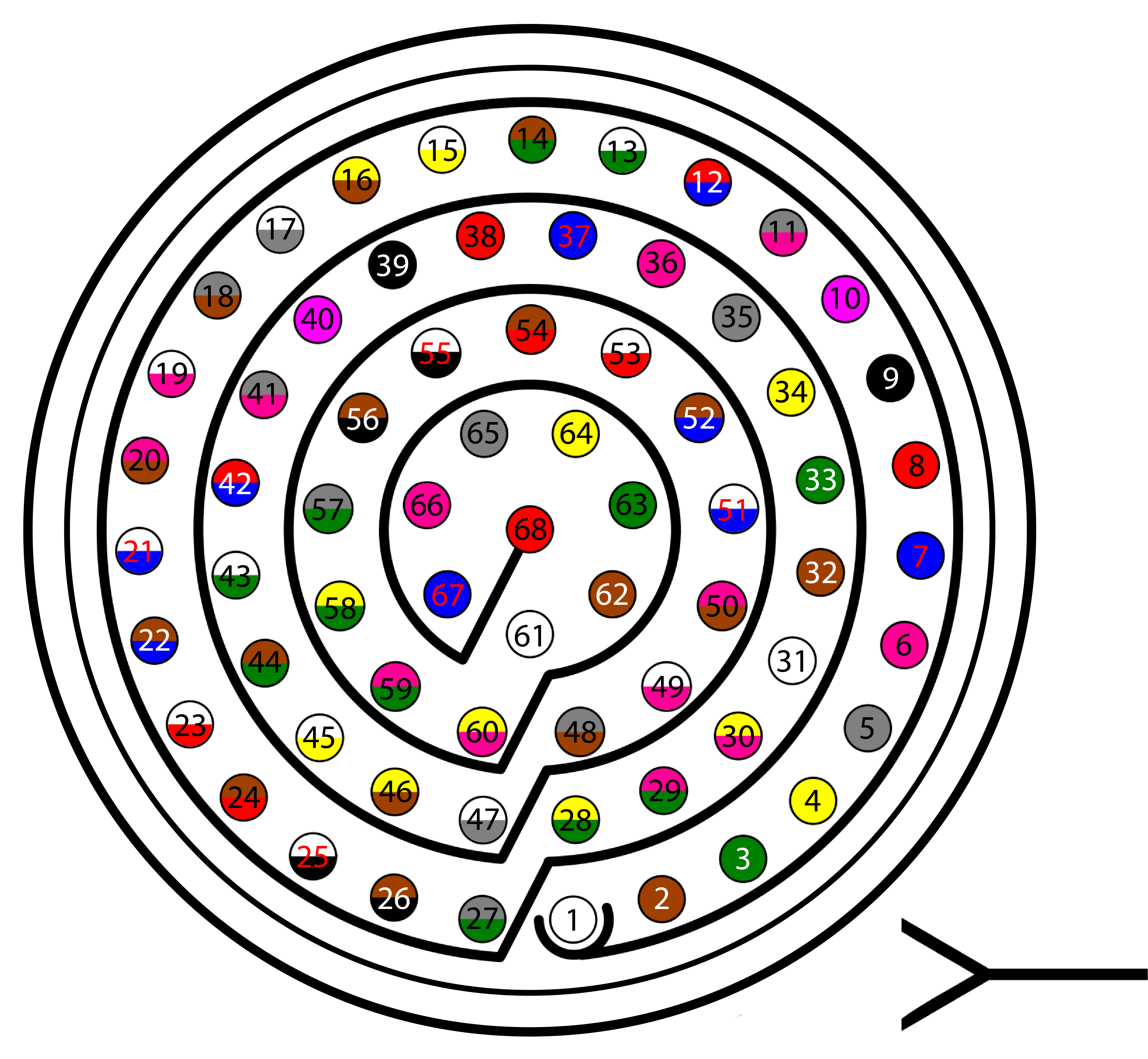
Connector colour code:
Connector HEW.LM.368.XLNP
Harness plug
Warning
Check the pin number before connecting. The colour code is repeated 3 times due to the amount of pins. First section (yellow) corresponds to pins 1-30, the second section (blue) to pins 31-60 and the third one (red) to pins 61-68. Pin number increases following the black line of the pictures above: counterclockwise for the connector and clockwise for the plug.
PIN |
Color code |
PIN |
Color code |
|---|---|---|---|
1 |
White |
35 |
Gray |
2 |
Brown |
36 |
Pink |
3 |
Green |
37 |
Blue |
4 |
Yellow |
38 |
Red |
5 |
Gray |
39 |
Black |
6 |
Pink |
40 |
Violet |
7 |
Blue |
41 |
Gray – Pink |
8 |
Red |
42 |
Red – Blue |
9 |
Black |
43 |
White – Green |
10 |
Violet |
44 |
Brown – Green |
11 |
Gray – Pink |
45 |
White – Yellow |
12 |
Red – Blue |
46 |
Yellow – Brown |
13 |
White – Green |
47 |
White – Gray |
14 |
Brown – Green |
48 |
Gray – Brown |
15 |
White – Yellow |
49 |
White – Pink |
16 |
Yellow – Brown |
50 |
Pink – Brown |
17 |
White – Gray |
51 |
White – Blue |
18 |
Gray – Brown |
52 |
Brown – Blue |
19 |
White – Pink |
53 |
White – Red |
20 |
Pink – Brown |
54 |
Brown – Red |
21 |
White – Blue |
55 |
White – Black |
22 |
Brown – Blue |
56 |
Brown – Black |
23 |
White – Red |
57 |
Gray – Green |
24 |
Brown – Red |
58 |
Yellow – Green |
25 |
White – Black |
59 |
Pink – Green |
26 |
Brown – Black |
60 |
Yellow – Pink |
27 |
Grey – Green |
61 |
White |
28 |
Yellow – Green |
62 |
Brown |
29 |
Pink – Green |
63 |
Green |
30 |
Yellow – Pink |
64 |
Yellow |
31 |
White |
65 |
Grey |
32 |
Brown |
66 |
Pink |
33 |
Green |
67 |
Blue |
34 |
Yellow |
68 |
Red |
Flight Termination System (FTS)
Flight Termination System
Veronte Autopilot 1x integrates two different FTS pins (42 and 43):
FTS1 - Deadman (Pin 42): On this pin, Autopilot 1x outputs a square wave with A = ~5ms and B = ~5ms (3.3V). Its frequency can be higher right after the rebooting (around 300-400Hz), but A and B must be always < 8ms.
FTS2 - !SystemOK (Pin 43): Its output is 0V when the system is working as expected and 3.3V when some error is detected. In detail, pin 43 goes high if A > 8ms or B > 8ms in the deadman signal sent by the Main Processor Unit (MPU).