Troubleshooting
In case of any issue with software, read the Troubleshooting section of the manual for the corresponding software.
Warning
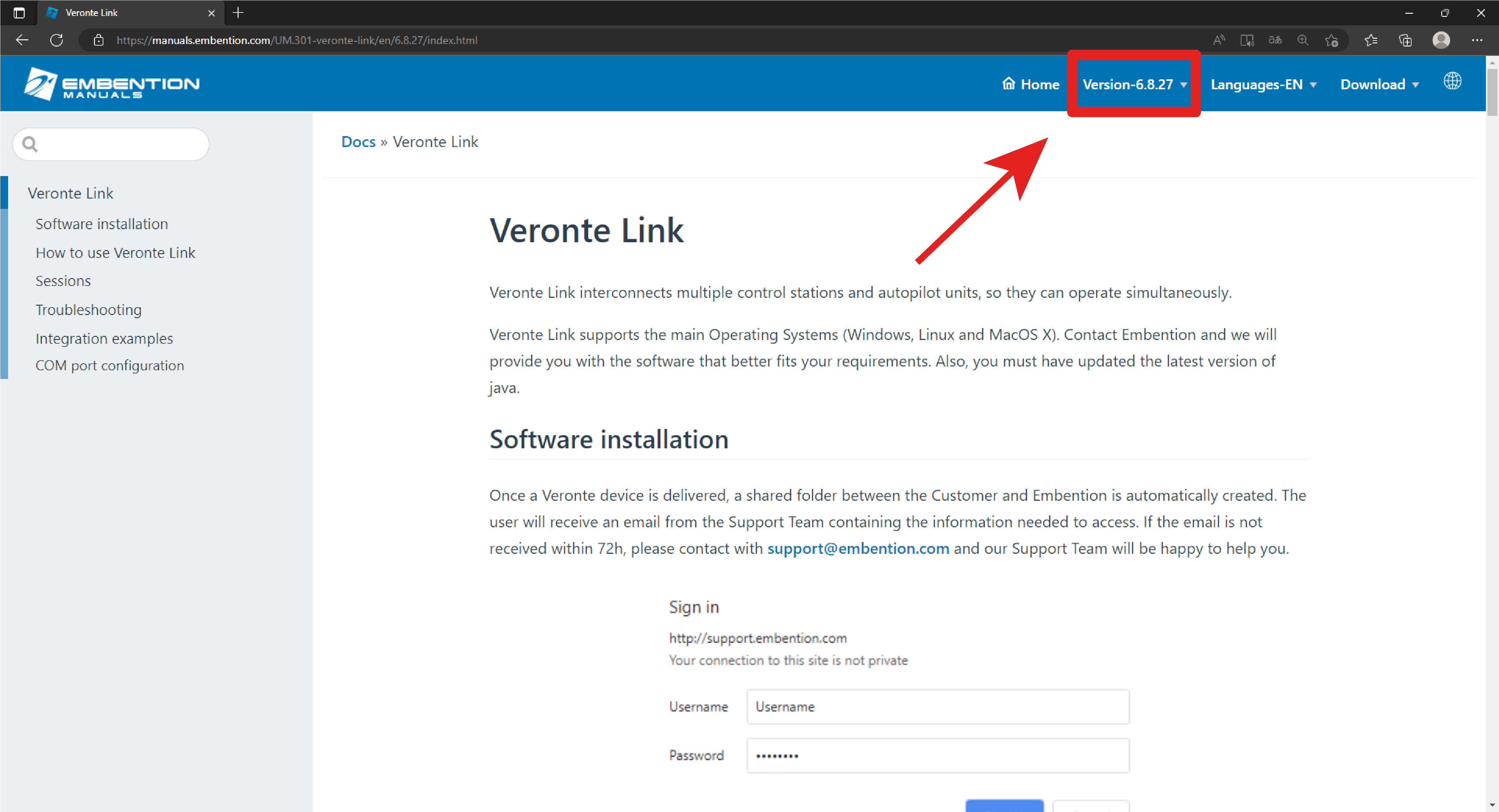
Select your version before reading any user manual for software. The following image shows where to select a version from any Embention user manual.
Maintenance mode
Maintenance mode is the main troubleshooting tool that Veronte Autopilot 1x puts at the user disposal. While in maintenance mode, all communication channels are enabled by default, so it is possible to connect with Autopilot 1x through any of its configuration interfaces, no matter its current configuration.
The main use of maintanance mode is to solve issues related to the current configuration, mainly related with communication or memory writting issues.
While in maintenance mode, it is possible to perform actions such as force the load of a new configuration file or format the SD card.
If at some point the communication with Autopilot 1x is lost, it is possible to use maintenance mode to go back to a previous state of the configuration (as long as it was exported previously), format the SD card to start over or update the unit’s firmware.
Tip
It is heavily recommended to always use maintenance mode to load a new configuration that is very different from the current one.
How to enter in maintenance mode
There are two ways to enter in maintenance mode: using software or forcing it.
Using software to enter in maintenance mode
To enter in maintenance mode using software, read the maintenance mode section of the manual for the corresponding software.
Forcing maintenance mode
There are two ways to force the maintenance mode: using power supply or using the I2C pins.
Using the power supply to force maintenance mode
When communication with the unit is lost, it is possible to active maintenance mode by power input.
In order to active maintenance mode, power cycle the Veronte Autopilot 1x repetively with a period of 1 second. After 30 cycles, the autopilot will enter in maintenance mode.
Autopilot 1x might enter in maintenance mode if a problem with the power supply is detected upon boot up (voltage or current is out of range).
How to power cycle an autopilot
Using the I2C pins to enter in maintenance mode
To enter in maintenance mode with I2C, connect both I2C pins each other, then power up the Veronte Autopilot 1x. Both pins are I2C_CLK (number 31) and I2C_DATA (number 32) according to the pinout.
Pinout changes from Autopilot 1x 4.8
The pinout for 4.5 and 4.8 versions are very similar, but they have several differences.
To prevent any confusion, the following table shows the pinout for both versions. The different pins
are marked with  , all the rest have the same function.
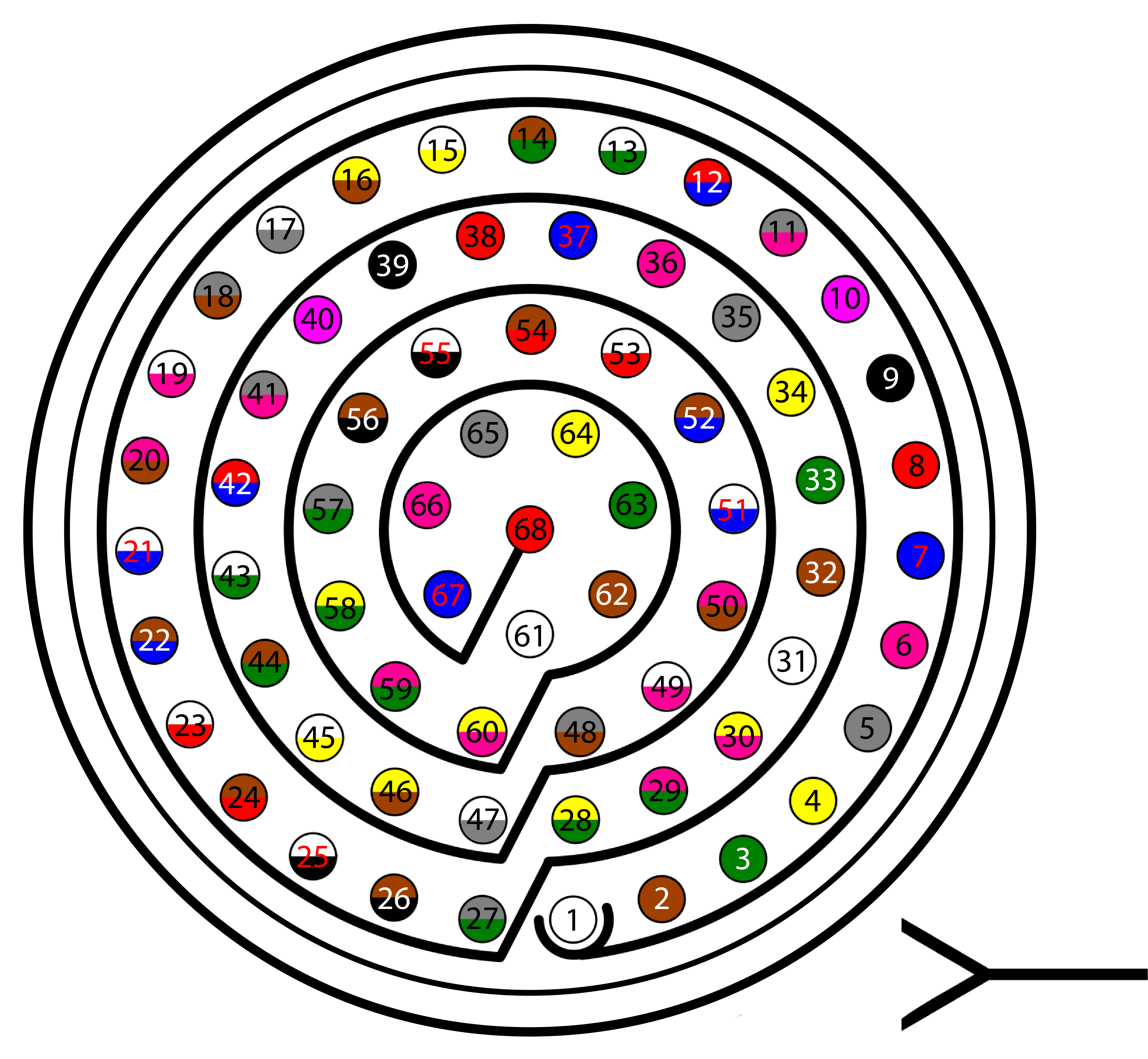
68 pin connector for both versions
Pin |
Signal |
Type |
Comments |
|---|---|---|---|
1 |
I/O1 |
I/O |
PWM / Digital I/O signal (0-3.3V). Protected against ESD and short circuit |
2 |
I/O2 |
I/O |
PWM / Digital I/O signal (0-3.3V). Protected against ESD and short circuit |
3 |
I/O3 |
I/O |
PWM / Digital I/O signal (0-3.3V). Protected against ESD and short circuit |
4 |
I/O4 |
I/O |
PWM / Digital I/O signal (0-3.3V). Protected against ESD and short circuit |
5 |
I/O5 |
I/O |
PWM / Digital I/O signal (0-3.3V). Protected against ESD and short circuit |
6 |
I/O6 |
I/O |
PWM / Digital I/O signal (0-3.3V). Protected against ESD and short circuit |
7 |
I/O7 |
I/O |
PWM / Digital I/O signal (0-3.3V). Protected against ESD and short circuit |
8 |
I/O8 |
I/O |
PWM / Digital I/O signal (0-3.3V). Protected against ESD and short circuit |
9 |
GND |
GROUND |
Ground signal for actuators 1-8 |
10 |
I/O9 |
I/O |
PWM / Digital I/O signal (0-3.3V). Protected against ESD and short circuit |
11 |
I/O10 |
I/O |
PWM / Digital I/O signal (0-3.3V). Protected against ESD and short circuit |
12 |
I/O11 |
I/O |
PWM / Digital I/O signal (0-3.3V). Protected against ESD and short circuit |
13 |
I/O12 |
I/O |
PWM / Digital I/O signal (0-3.3V). Protected against ESD and short circuit |
14 |
I/O13 |
I/O |
PWM / Digital I/O signal (0-3.3V). Protected against ESD and short circuit |
15 |
I/O14 |
I/O |
PWM / Digital I/O signal (0-3.3V). Protected against ESD and short circuit |
16 |
I/O15 |
I/O |
PWM / Digital I/O signal (0-3.3V). Protected against ESD and short circuit |
17 |
I/O16 |
I/O |
PWM / Digital I/O signal (0-3.3V). Protected against ESD and short circuit |
18 |
GND |
GROUND |
Ground signal for actuators 9-16 |
19 |
RS 232 TX |
Output |
RS 232 Output (-13.2V to 13.2V Max, -5.4V to 5.4V Typical). Protected against ESD and short circuit |
20 |
RS 232 RX |
Input |
RS 232 Input (-25V to 25V Max, -0.6V Low and 2.4V High Threshold). Protected against ESD and short circuit |
21 |
GND |
GROUND |
Ground signal for buses |
22 |
Analog 4 |
Input Analog |
Input 0-3.3V. Protected against ESD and short circuit |
23 |
Analog 5 |
Input Analog |
Input 0-3.3V. Protected against ESD and short circuit |
24 |
GND |
GROUND |
Ground signal for buses |
25 |
CanA P |
I/O |
CANbus interface, up to 1Mbps (2.3V Typical, 1.2V-2.3V Differential). Protected against ESD |
26 |
CanA N |
I/O |
Twisted pair with a 120 ohms Zo recommended (2.3V Typical, 1.2V-2.3V Differential). Protected against ESD |
27 |
|
|
|
|
|
|
|
28 |
CANB_P |
I/O |
CANbus interface. It supports data rates up to 1 Mbps. Protected against ESD |
29 |
CANB_N |
I/O |
Twisted pair with a 120 ohms Zo recommended. Protected against ESD |
30 |
GND |
GROUND |
Ground signal for buses |
31 |
I2C_CLK |
Output |
Clk line for I2C bus (0.3V to 3.3V). Protected against ESD and short circuit |
32 |
I2C_DATA |
I/O |
Data line for I2C bus (0.3V to 3.3V). Protected against ESD and short circuit |
33 |
GND |
GROUND |
Ground for 3.3V power supply |
34 |
3.3V |
POWER |
3.3V - 100mA power supply. Protected against ESD short circuit with 100mA resettable fuse |
35 |
GND |
GROUND |
Ground for 5V power supply |
36 |
5V |
POWER |
5V – 100mA power supply. Protected against ESD short circuit with 100mA resettable fuse |
37 |
GND |
GROUND |
Ground for analog signals |
38 |
ANALOG_1 |
Input |
Analog input 0-3.3V. Protected against ESD and short circuit |
39 |
ANALOG_2 |
Input |
Analog input 0-3.3V. Protected against ESD and short circuit |
40 |
ANALOG_3 |
Input |
Analog input 0-3.3V. Protected against ESD and short circuit |
41 |
|
|
|
|
|
|
|
42 |
FTS1_OUT |
Output |
Deadman signal from comicro. Protected against ESD and short circuit |
43 |
FTS2_OUT |
Output |
!SystemOK Bit. Protected against ESD and short circuit |
44 |
|
|
|
|
|
|
|
45 |
|
|
|
|
|
|
|
46 |
|
|
|
|
|
|
|
47 |
GND |
GROUND |
Ground signal comicro power supply |
48 |
V_ARB_VCC |
POWER |
Veronte comicro power (6.5V to 36V). Protected against ESD and reverse polarity |
49 |
FTS3_OUT_MPU |
Output |
MPU alive voting signal, to use with 4xVeronte. It is a Square Wave at [100,125] Hz. Protected against ESD and short circuit |
50 |
OUT_RS485_P |
Output |
Non-inverted output from RS485 bus (-7V to 12V Max, -2.3V to 2.3V Typical). Protected against ESD and short circuit |
51 |
OUT_RS485_N |
Output |
Inverted output from RS485 bus (-7V to 12V Max, -2.3V to 2.3V Typical). Protected against ESD and short circuit |
52 |
IN_RS845_N |
Input |
Inverted input from RS485 bus (-7V to 12V Max, -2.3V to 2.3V Typical). Protected against ESD and short circuit |
53 |
IN_RS845_P |
Input |
Non-inverted output from RS485 bus (-7V to 12V Max, -2.3V to 2.3V Typical). Protected against ESD and short circuit |
54 |
RS-485_GND |
GND |
Ground for RS-485 bus |
55 |
EQEP_A |
I/O |
DIGITAL output / DIGITAL input / Encoder quadrature input A (0-3.3V). Protected against ESD and short circuit |
56 |
EQEP_B |
I/O |
DIGITAL output / DIGITAL input / Encoder quadrature input B (0-3.3V). Protected against ESD and short circuit WARNING!: Only use it as digital I/O with Veronte units of Hardware version 4.5 or lower |
57 |
EQEP_S |
I/O |
DIGITAL output / DIGITAL input / Encoder strobe input (0-3.3V). Protected against ESD and short circuit |
58 |
EQEP_I |
I/O |
DIGITAL output / DIGITAL input / Encoder index input A (0-3.3V). Protected against ESD and short circuit |
59 |
GND |
GROUND |
Ground for encoders |
60 |
V_USB_DP |
I/O |
Veronte USB data line. Protected against ESD |
61 |
V_USB_DN |
I/O |
Veronte USB data line. Protected against ESD |
62 |
|
|
|
|
|
|
|
63 |
FTS_OUT_MPU |
Output |
Abort mission voting signal from MPU, to use with 4xVeronte. Bit Low (0V) if mission OK. High (3.3V) if mission wants to be terminated. Protected against ESD and short circuit |
64 |
FTS2_OUT_MPU |
Output |
Abort mission voting signal 2 from MPU, to use with 4xVeronte. Bit Low (0V) if mission OK. High (3.3V) if mission wants to be terminated. Protected against ESD and short circuit |
65 |
GND |
GROUND |
Veronte ground input |
66 |
GND |
GROUND |
Veronte ground input |
67 |
VCC |
POWER |
Veronte power supply (6.5V to 36V). Protected against ESD and reverse polarity. Warning Both pins are common. They MUST be connected to the same power supply. |
68 |
VCC |
POWER |
Warning
Remember!! All GND pins are common.