Communication
This section explains the steps to follow to set up radio communication between Autopilots 1x. Follow the steps below:
GND unit configuration
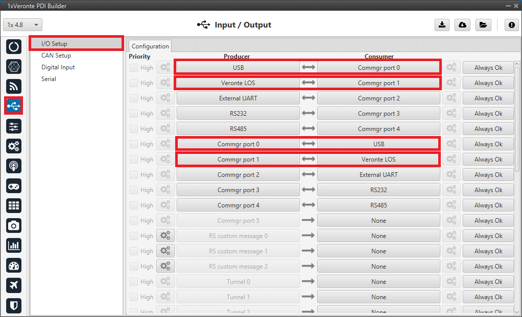
Go to Input/Output menu \(\rightarrow\) I/O Setup panel.
The following connections betweens producers and consumers must be configured here:
USB \(\leftrightarrow\) Commgr port 0.
Veronte LOS \(\leftrightarrow\) Commgr port 1.
Commgr port 0 \(\leftrightarrow\) USB.
Commgr port 1 \(\leftrightarrow\) Veronte LOS.
Note
It is not necessary to use these particular COM Manager ports, however, the connections between these producer and consumer must be bidirectional.
Ground unit - Input/Output configuration
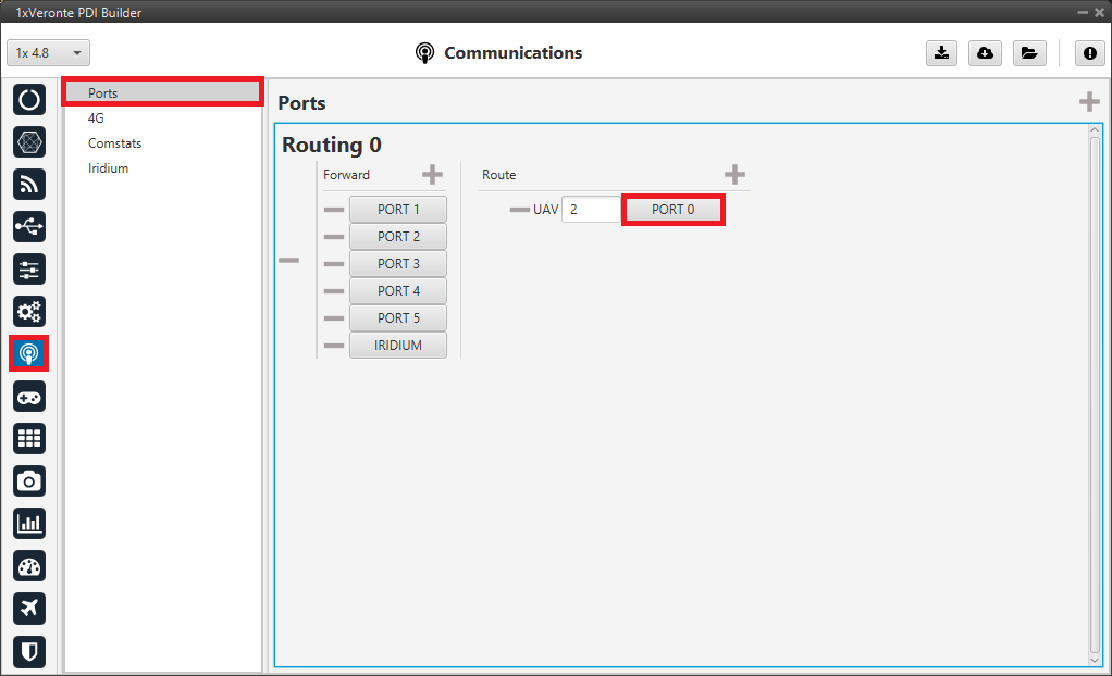
Go to Communications menu \(\rightarrow\) Ports panel.
In order to establish the connection between the PC and the 1x air unit thanks to the radio connection with the 1x ground, a routing of the communications must be made to the port to which the USB consumer is connected.
Therefore, a routing of Address 2 (address of the Veronte applications) is made through Commgr port 0.
This way, any messages that are received through a Commgr Port (i.e. through Veronte LOS) with address 2, will be re-routed through Port 0 (USB) and received by Veronte Ops software, including any messages generated by 1x ground unit itself.
Ground unit - Routing configuration
Air unit configuration
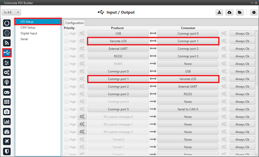
Go to Input/Output menu \(\rightarrow\) I/O Setup panel.
Configure the following connections between producers and consumers:
Veronte LOS \(\leftrightarrow\) Commgr port 1.
Commgr port 1 \(\leftrightarrow\) Veronte LOS.
Note
It is not necessary to use these particular COM Manager ports, however, the connections between these producer and consumer must be bidirectional.
Air unit - Input/Output configuration
For more information, visit the Input/Output - Configuration section of the 1x PDI Builder user manual.
GND-Air communication configuration
To establish a proper communication between the ground and air units, the telemetry and sniffer menus must be configured, respectively.
A simple example of use between a ground unit and an air unit is shown below:
In the 1x ground unit:
Go to Telemetry menu \(\rightarrow\) Telemetry panel \(\rightarrow\) Data link to VApp tab (for more information about this, see Data vectors - Telemetry section of 1x PDI Builder user manual).
Add the variables: Absolute: UAV position, Yaw, Pitch and Roll.
Set a Frequency, it is recommended to set it to 10 Hz.
On Address, point to the 1x air unit (it is needed to have both units connected through the radio in order to be able to see them on the menu).

1x ground unit - Telemetry
For the 1x air unit:
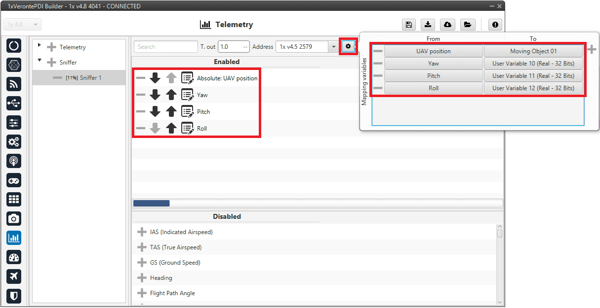
Go to Telemetry menu \(\rightarrow\) Sniffer panel (for more information about this, see Sniffer - Telemetry section of 1x PDI Builder user manual).
Add a new Sniffer.
Configure the same variables (keeping the same order) than in the ground unit.
On Address, point to the 1x ground unit.
In the gear next to it, configure the 4 incoming variables as System Variables: assign UAV Position to Moving Object and the 3 variables from attitude to 3 different User Variables (keeping the same order as well).
1x air unit - Sniffer
Radio pairing
In order to establish communication between the two units, it is necessary that the radios of both devices are paired. For this operation, there is an internal Digi radio in both Veronte Autopilots 1x.
Follow the steps described in the Digi internal radio - Integration example section of the 1x PDI Builder user manual, for both units, GND and air.
If everything went well, the user will be able to see the air unit in both Veronte Link and Veronte Ops by physically connecting only the ground unit.
Note
Autopilot 1x configured as the GND unit has address 4086 and the air unit has address 4085.
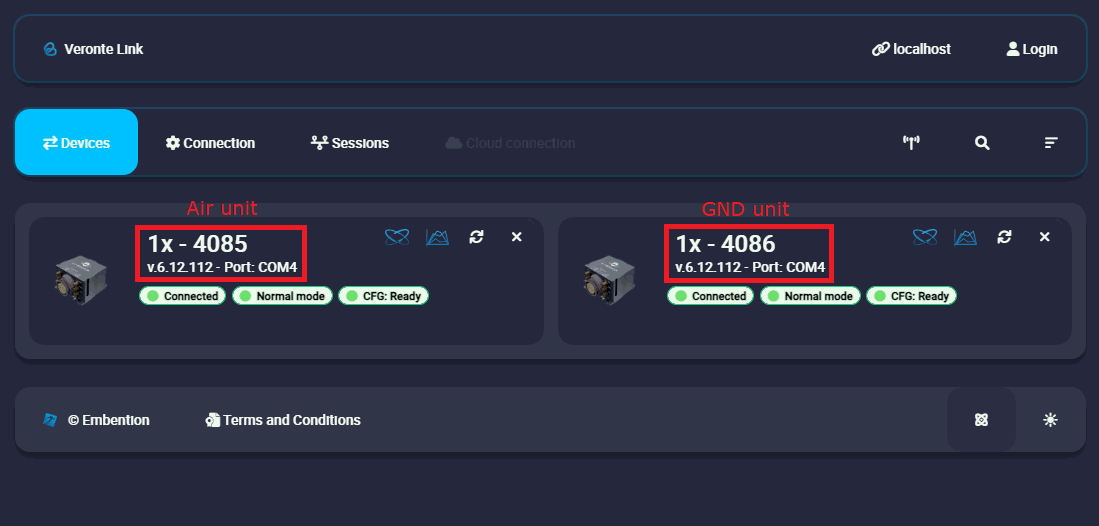
Radio pairing - Veronte Link
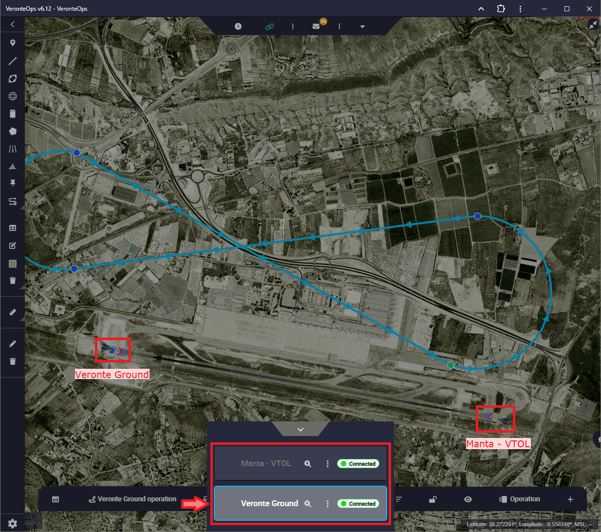
Radio pairing - Veronte Ops