 Stick
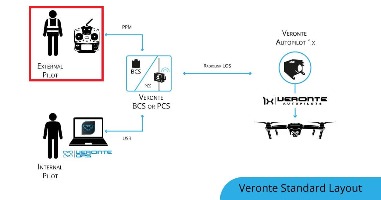
Veronte Standard Layout is the case where the 1x ground unit (or BCS/PCS) sends commands directly to the 1x air unit. So the stick is connected directly to the 1x ground unit.
Follow the steps below to perform a correct stick configuration on both units.
Ground unit
Go to Input/Output menu \(\rightarrow\) Digital Input panel.
Producer: CAP 0
Enabled
Select the pin to which the transmitter is connected, in this case EQEP_A
Edge detection: First rising edge
Consumer: PPM 0
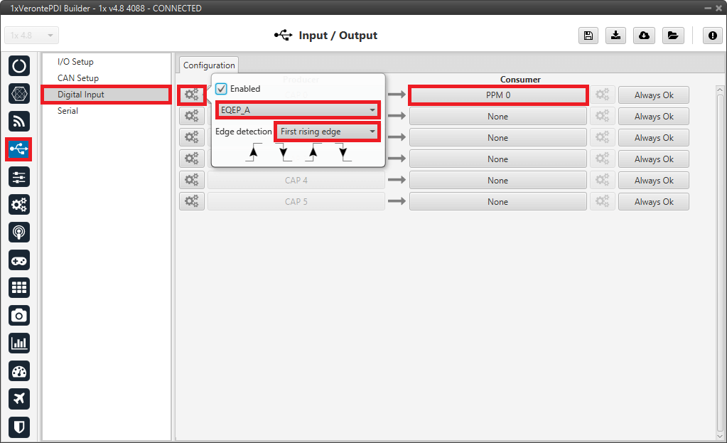
Ground unit - Digital Input configuration
Go to Connections menu \(\rightarrow\) GPIO panel.
Verify that the pin to which the transmitter is connected, in this case GPIO 16 (i.e., EQEP A), is set as input.
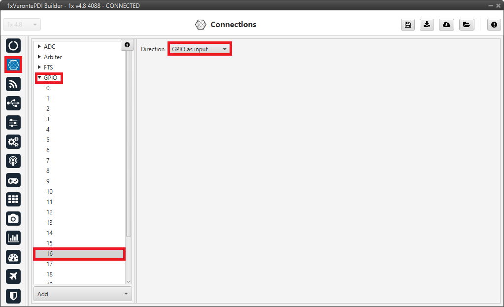
Ground unit - GPIO configuration
Go to Stick menu \(\rightarrow\) Transmitter 0 panel \(\rightarrow\) PPM tab.
Select the brand of transmitter that applies.
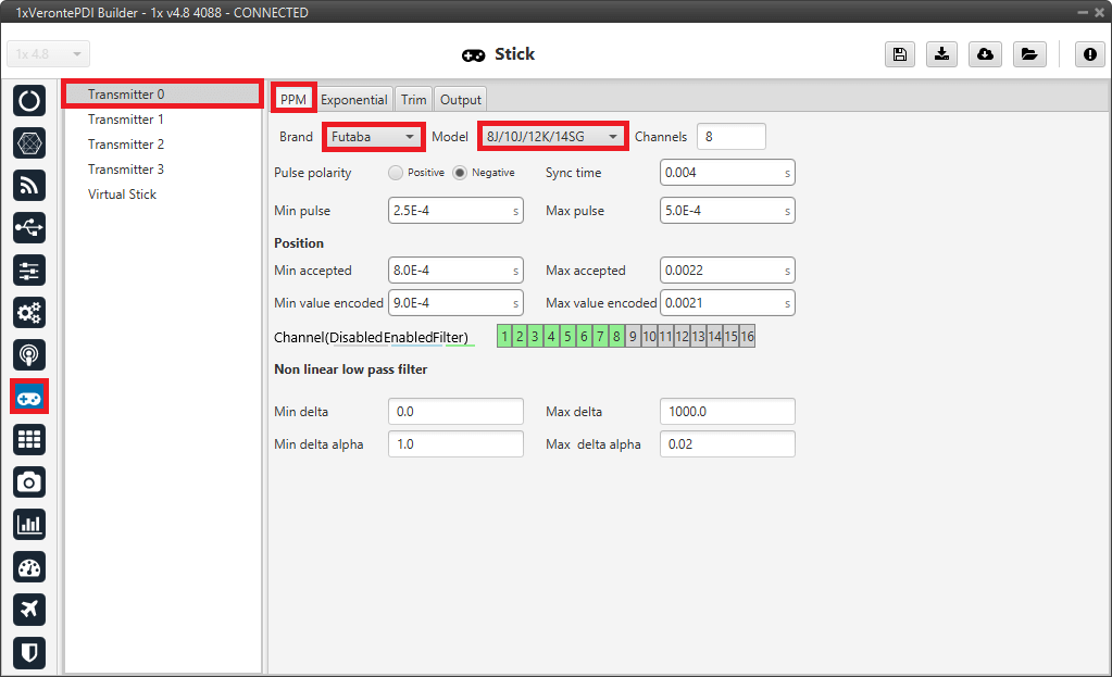
Ground unit - PPM configuration
Go to Stick menu \(\rightarrow\) Transmitter 0 panel \(\rightarrow\) Output tab.
Click on Enable and on Remote to send the stick information to the air unit. The recommended values for the configurable parameters have been entered here, as detailed in the Ouput - Stick section of the 1x PDI Builder user manual.
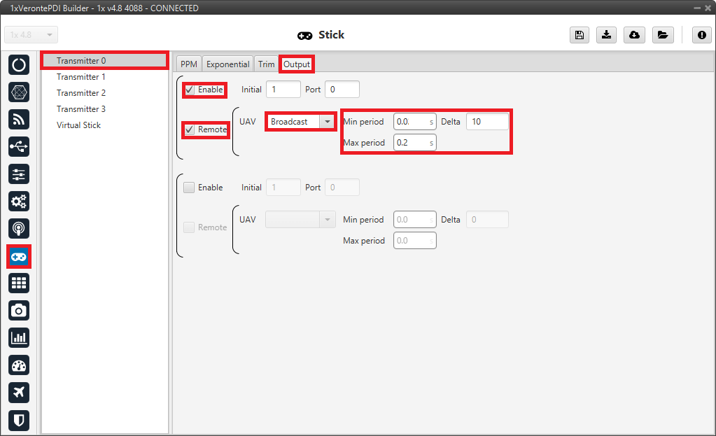
Ground unit - Output configuration
If all these settings are correct, users can check that ‘Stick PPM 0 not detected’ variable of the GND unit is true.

Stick PPM 0 not detected variable - True
Air unit
Go to Stick menu \(\rightarrow\) Transmitter 0 panel \(\rightarrow\) PPM tab.
Select the brand of transmitter that applies (make the same configuration as for the ground unit).
Go to Stick menu \(\rightarrow\) Transmitter 0 panel \(\rightarrow\) Output tab.
Just click on Enable.
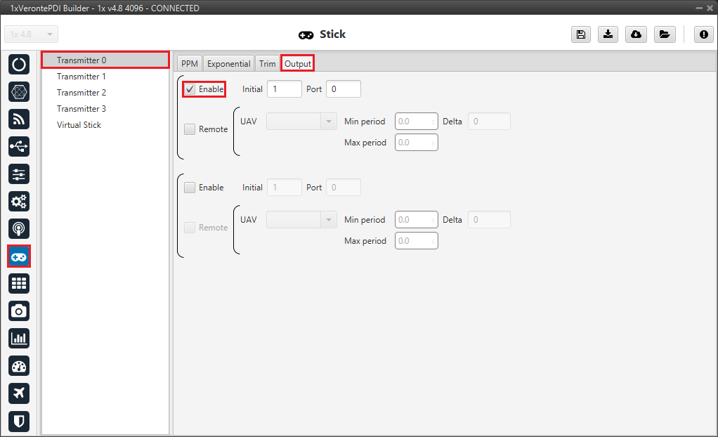
Air unit - Output configuration
Go to Block Programs menu \(\rightarrow\) Stick program \(\rightarrow\) Double click on the Stick block \(\rightarrow\) Edit sources.
Note
This is the Stick progam explained in the 1x Air configuration section of this manual.
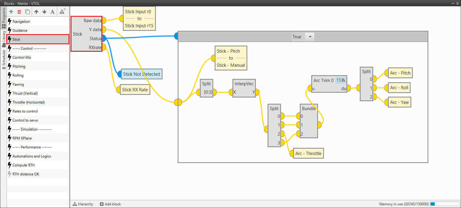
Stick program
Input the ground unit address to receive the stick information from that source and put it as the highest priority in the priority table. We recommend a Time Out of 0.4 s.
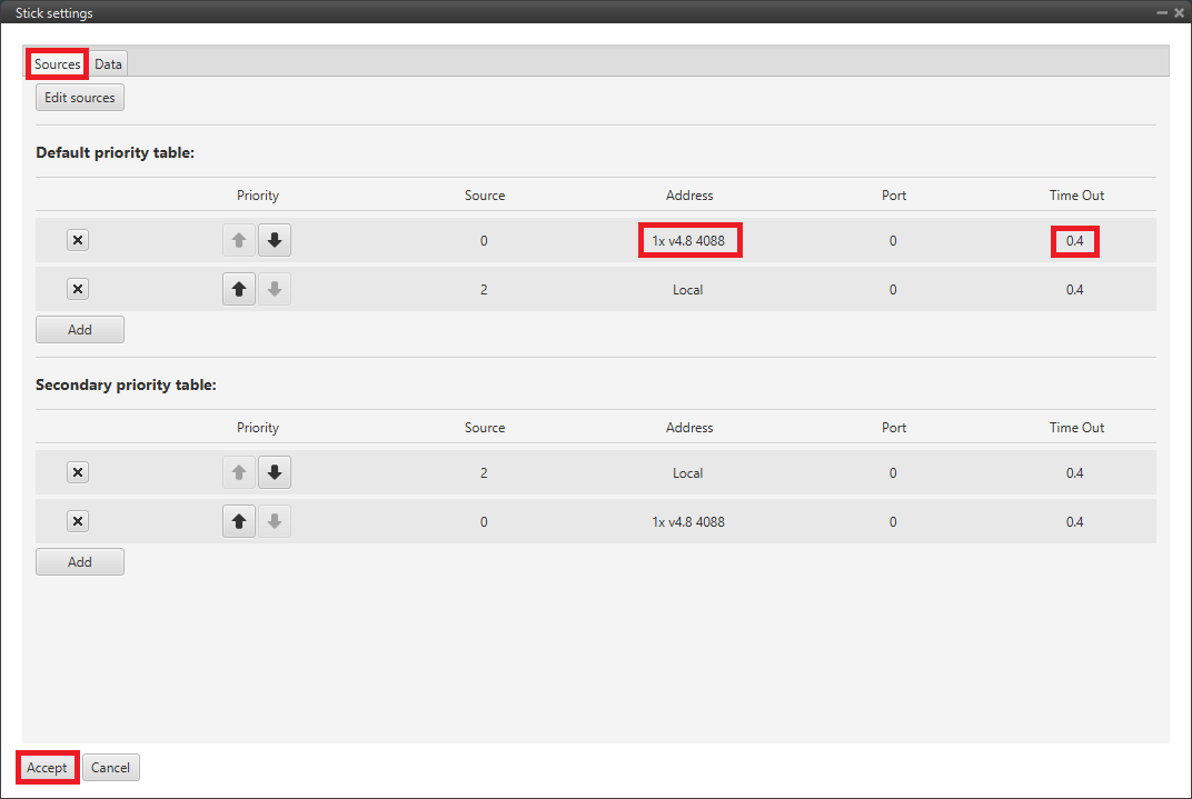
Air unit - Stick block configuration
Then, if all is correct, users can check that ‘Stick not detected’ variable of the AIR unit is true.

Stick not detected variable - True
And that means that the communication between the GND and the AIR unit is correctly configured.