Hardware Installation
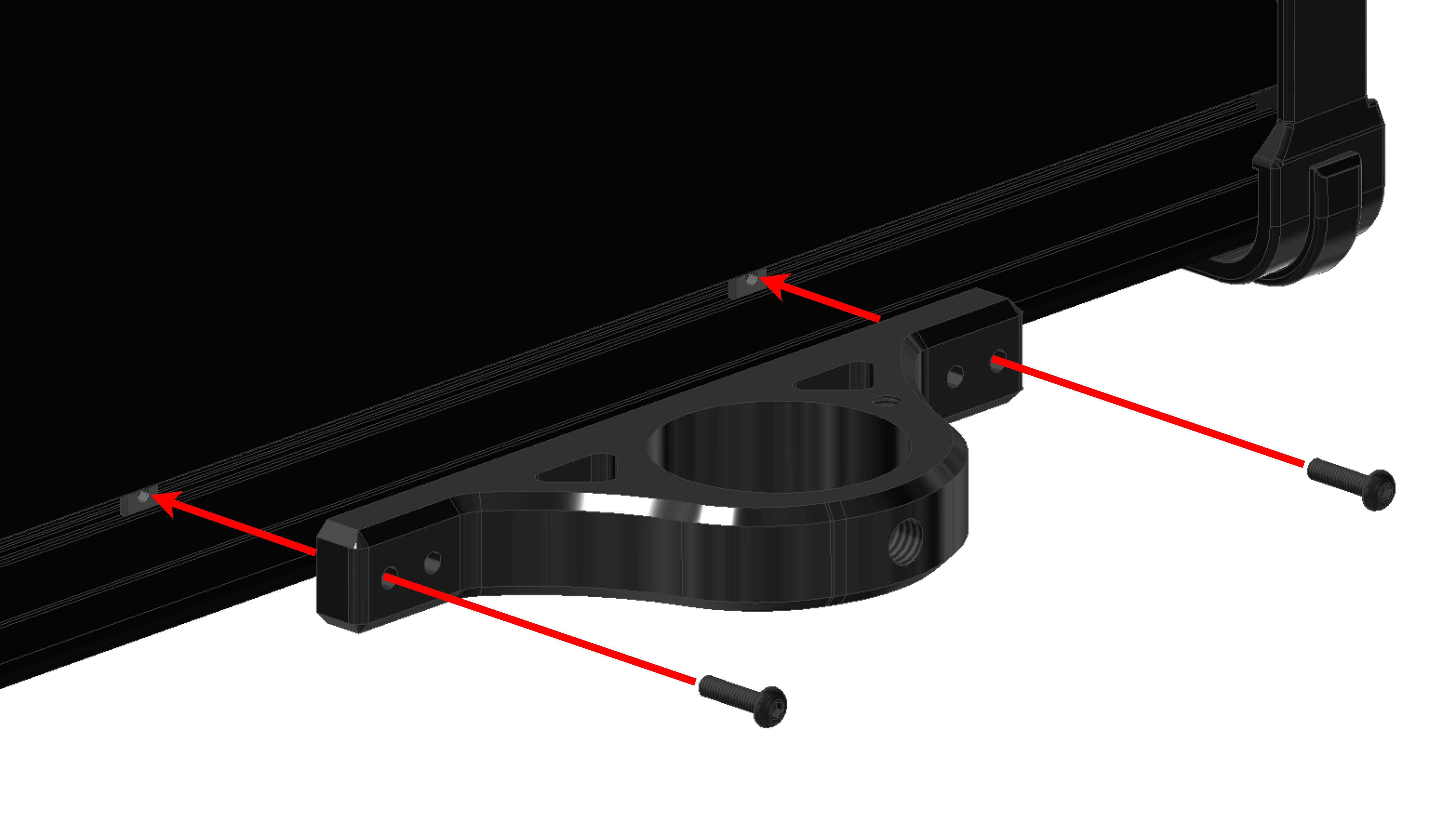
Attach a pole mount to the bottom of the PCS with two screws M3 x 12 mm.
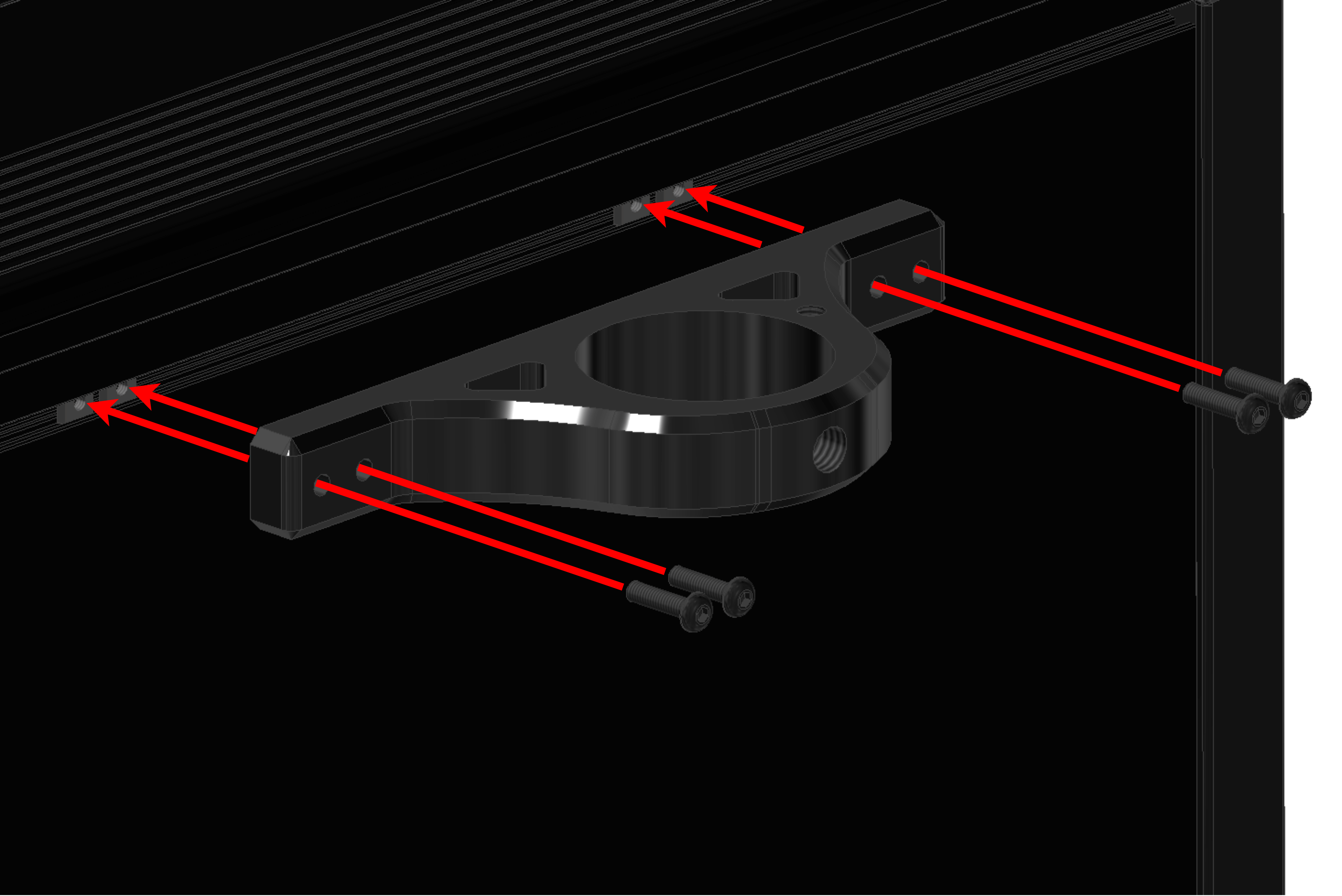
Attach a pole mount to the top of the PCS with four screws M3 x 12 mm.
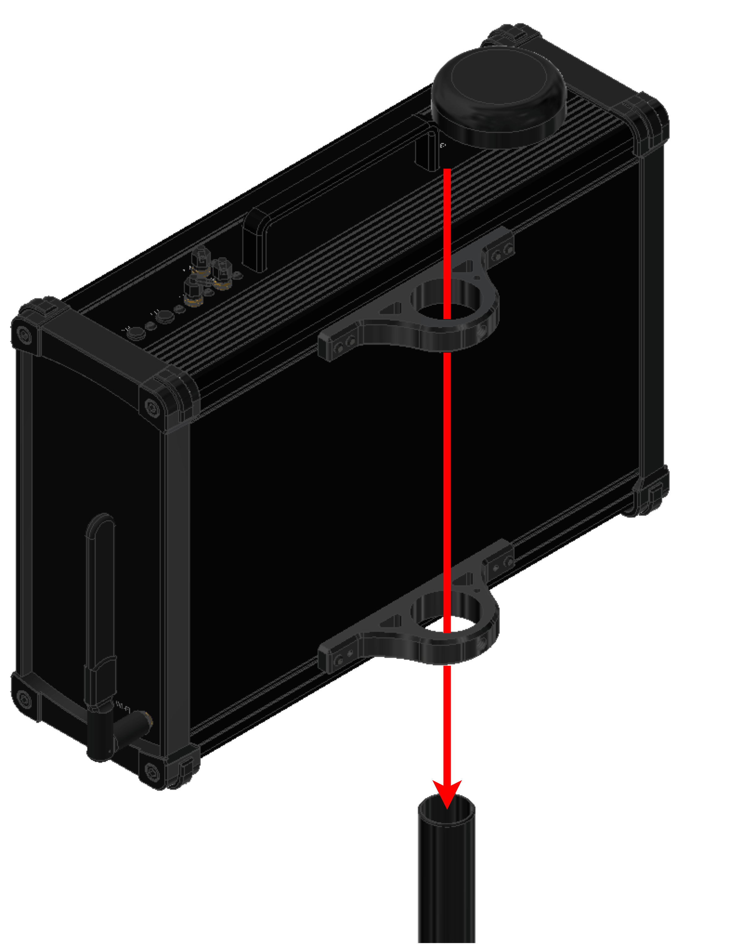
Pass the pole through both mounts.
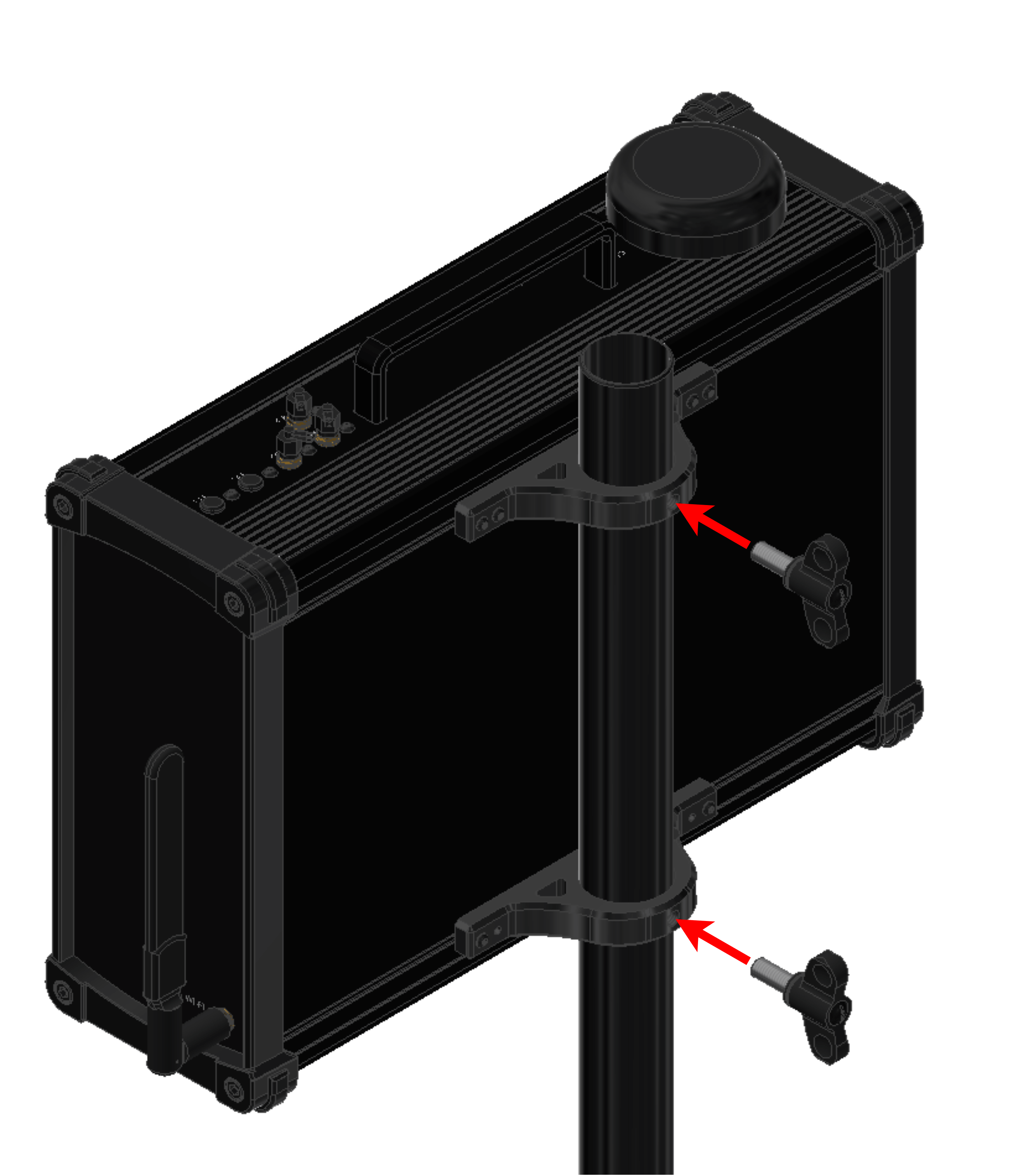
Screw two knobs to fix both mounts to the pole.
Place the adapter on the top of the pole.
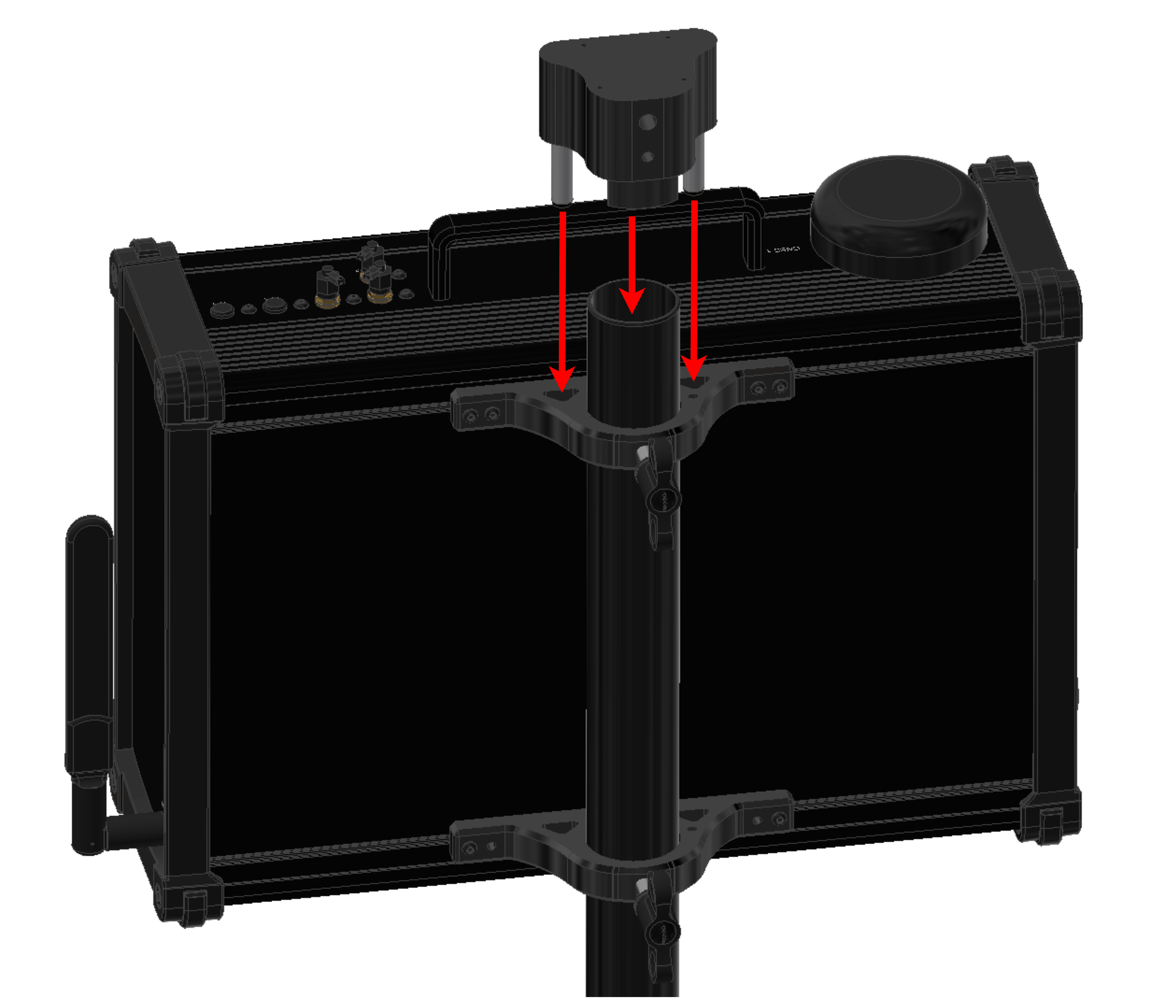
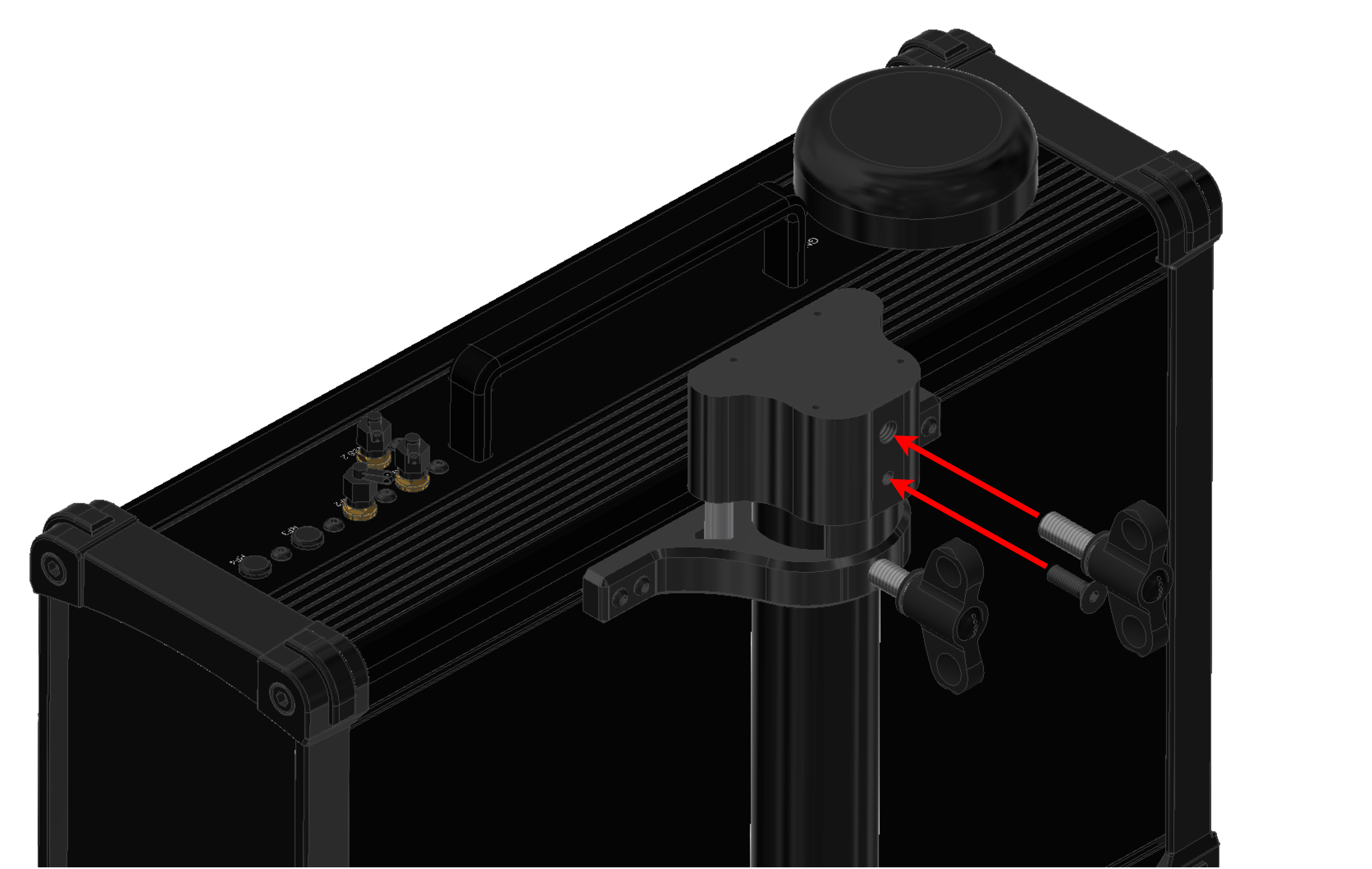
Screw one knob and one bolt M5 x 16 mm to fix the adapter on the pole.
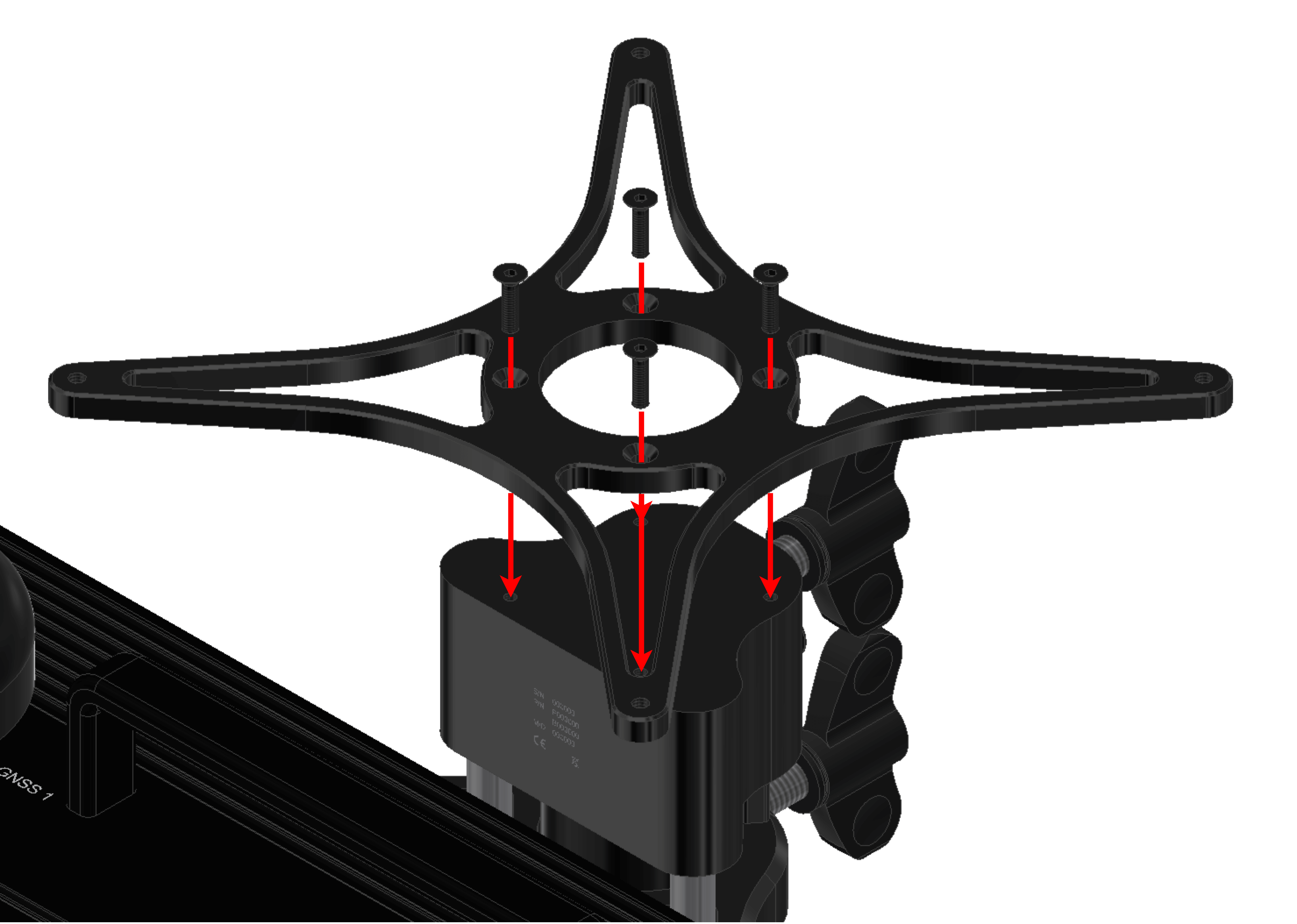
Screw the support on the adapter with four bolts M3 x 12 mm.
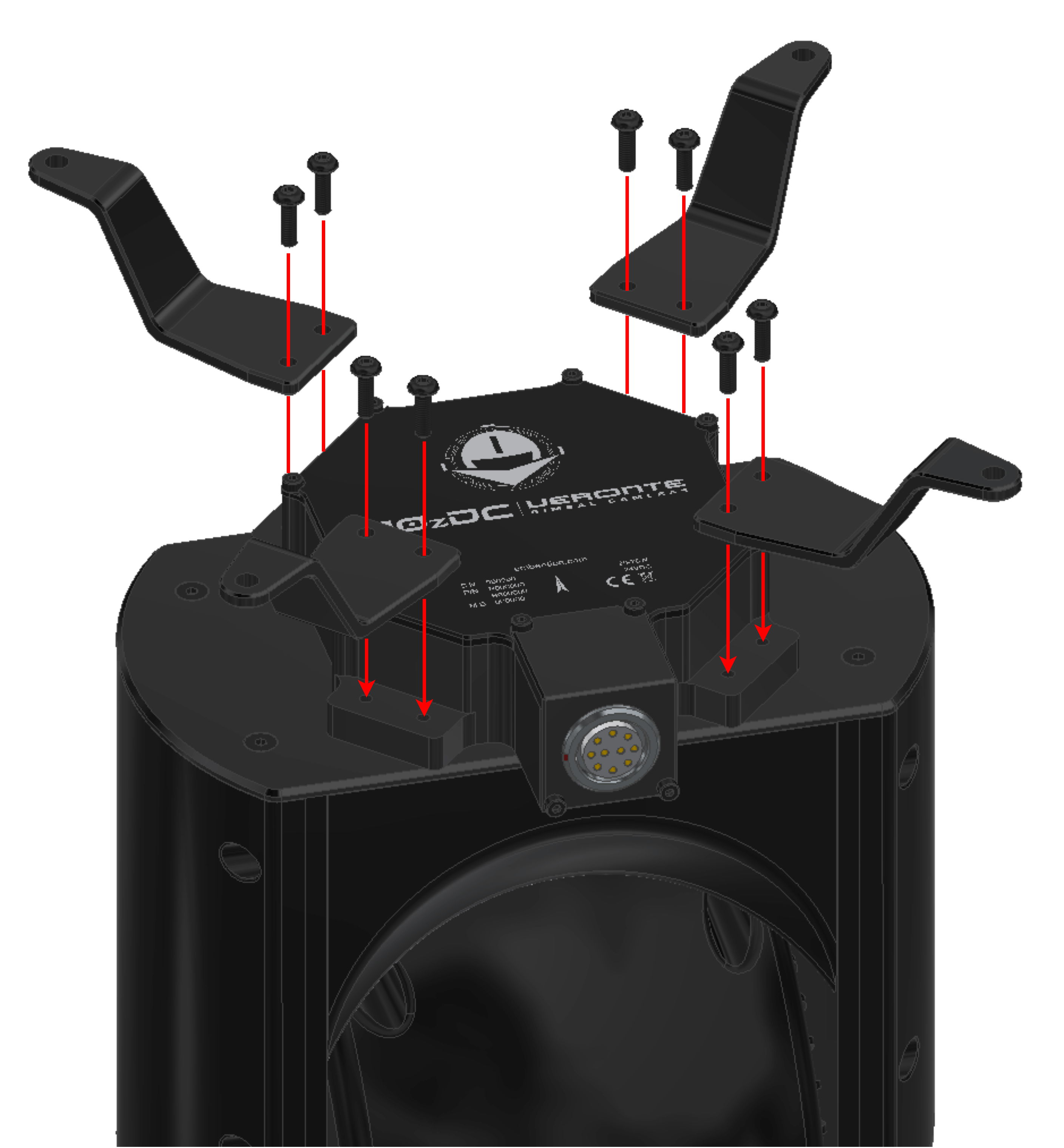
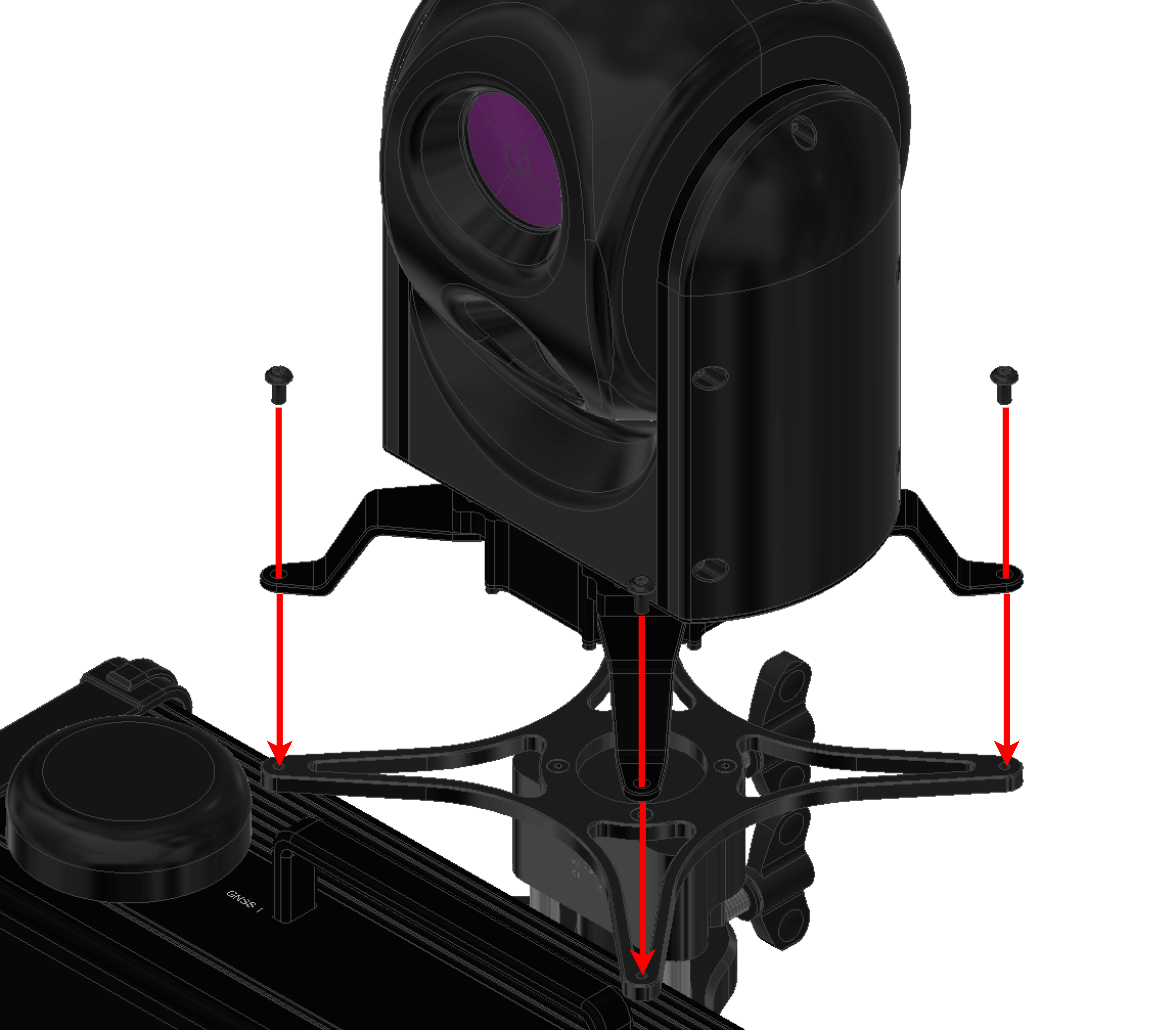
Attach the legs to the Gimbal with two bolts M3 x 10 mm for each one.
Fix the Gimbal to the support with four bolts M4 x 8 mm.
Connect the cables following the Interfaces - Technical section of the present manual.
Note
To know specific details about the electrical assembly, please consult:
For Gimbal 30z: Electrical - Hardware Installation section.
For PCS: Pinout - Hardware Installation section.