Hardware Installation
Mechanical Assembly
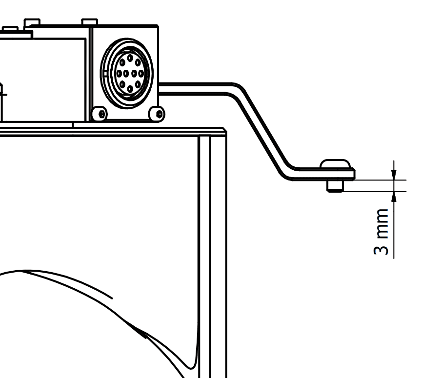
Veronte Gimbal 30z is fixed to the vehicle with four legs and included M4 screws. Each screw protrudes 3 mm from its leg, so the vehicle requires four screwed holes with 3 mm of minimum depth. Take a look to dimensions to know the distribution of holes and 30z dimensions.
There are two ways to assembly 30z to the vehicle according to the legs position.
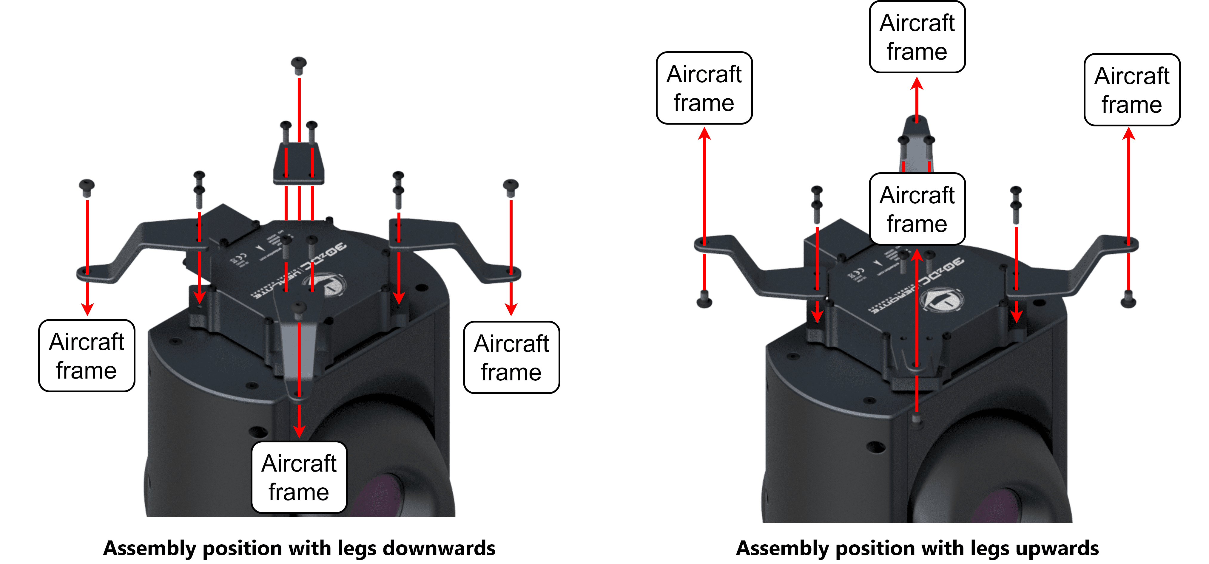
In addition, it can be mounted under or over the vehicle.
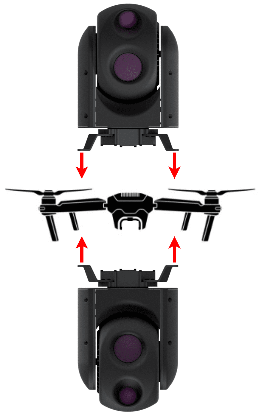
Assembly diagram
Dimensions
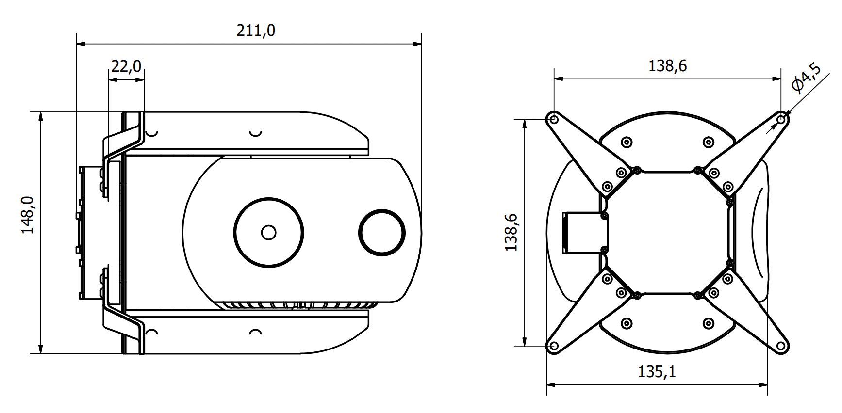
30z dimensions (mm)
Electrical
Pinout
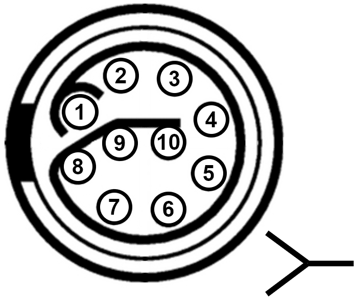
Gimbal 30z connector pinout - EGG.2B.310.CLL
Pin |
Abbreviation |
Name |
Function |
|---|---|---|---|
1 |
24 V |
24 volts input |
Input power supply (24 V DC) |
2 |
GND |
Ground |
Ground |
3 |
CAN H |
CAN high |
CAN communications to control cameras |
4 |
CAN L |
CAN low |
|
5 |
NO CONNECT |
||
6 |
|||
7 |
TDX+ |
Transmit data + |
Ethernet connection for video signals |
8 |
TDX- |
Transmit data - |
|
9 |
RDX+ |
Receive data + |
|
10 |
RDX- |
Receive data - |
|
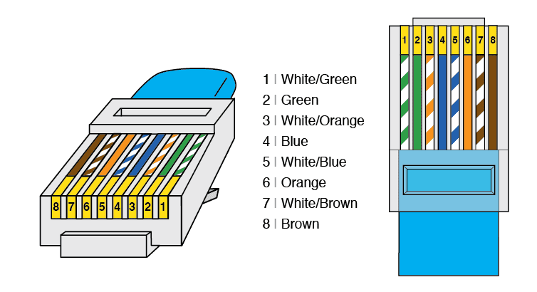
RJ45 T-568A pinout
Pin |
Colour |
Function |
|---|---|---|
1 |
White/Green |
Transmit data + |
2 |
Green |
Transmit data - |
3 |
White/Orange |
Receive data + |
6 |
Orange |
Receive data - |
CAN bus assembly
A resistor is required at each end of the CAN line. Nonetheless, Gimbal 30z does not include an internal resistor for CAN (120 \(\Omega\)), then both resistors may be placed on cable or PCB.
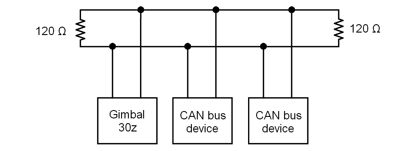
CAN assembly diagram example
Veronte Autopilot 1x includes a CAN resistor, so it is only required one more to build a CAN line.
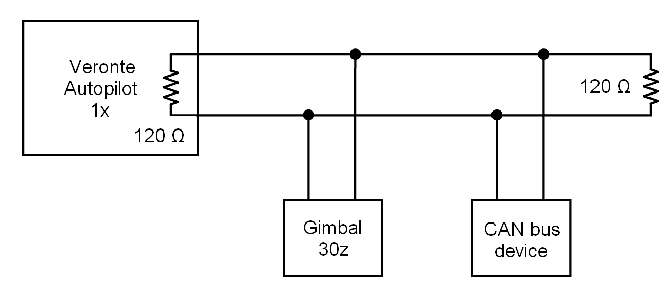
CAN assembly diagram example with 1x