Datalink Kit F/G - Silvus Modem
Hardware Installation
First of all, to access the expansion bay, read Expansion bay access section of this manual.
Screw the switch against the plate with the switch support and two mushoom bolts M3 x 5.
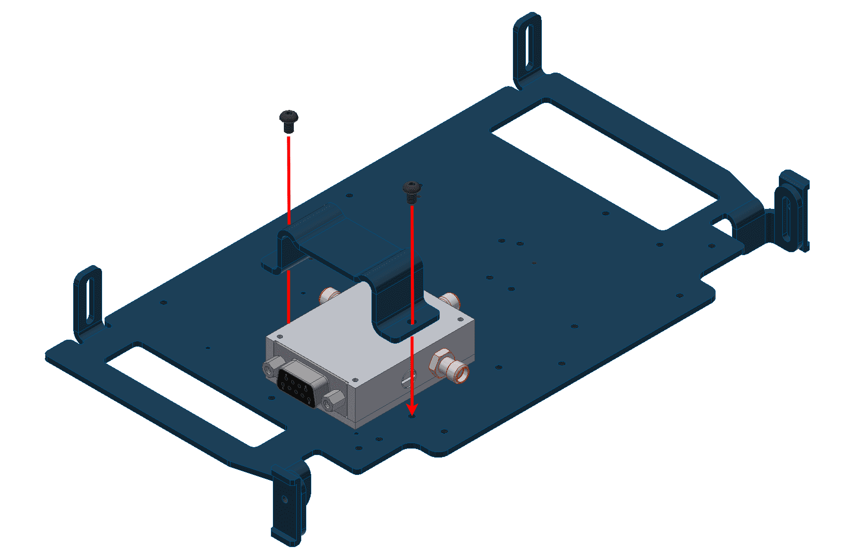
Hardware Silvus installation - Step 2
Attach the switch connector.
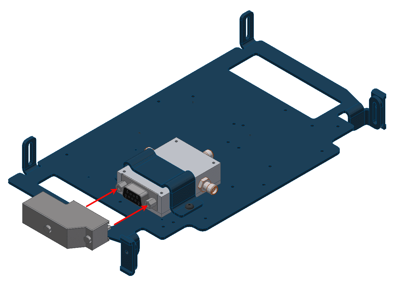
Hardware Silvus installation - Step 3
Screw the modem on the opposite side of the plate with four screws M2 x 20. Place two thermal pads on the top and the bottom.
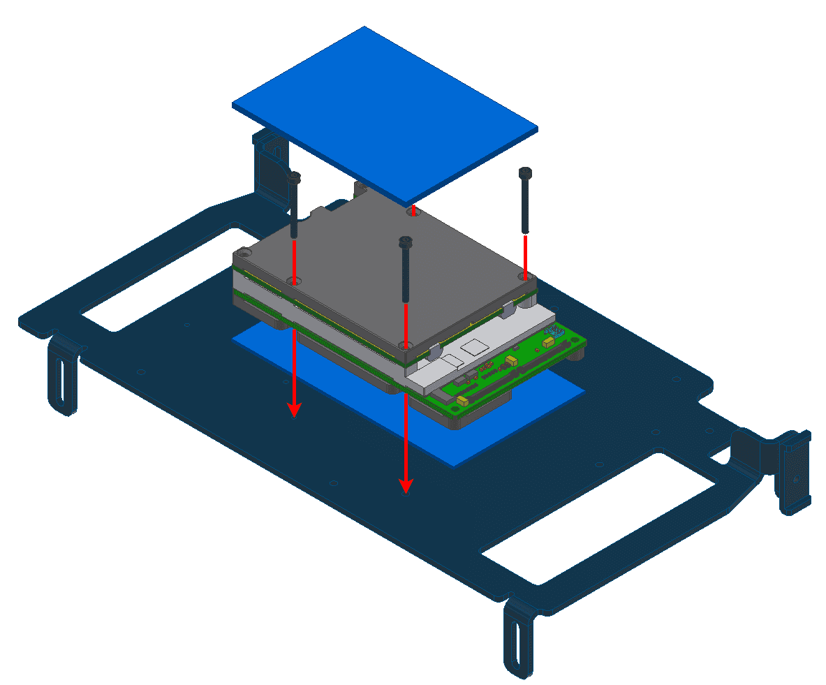
Hardware Silvus installation - Step 4
Connect the modem to the switch as indicated in the following figure:
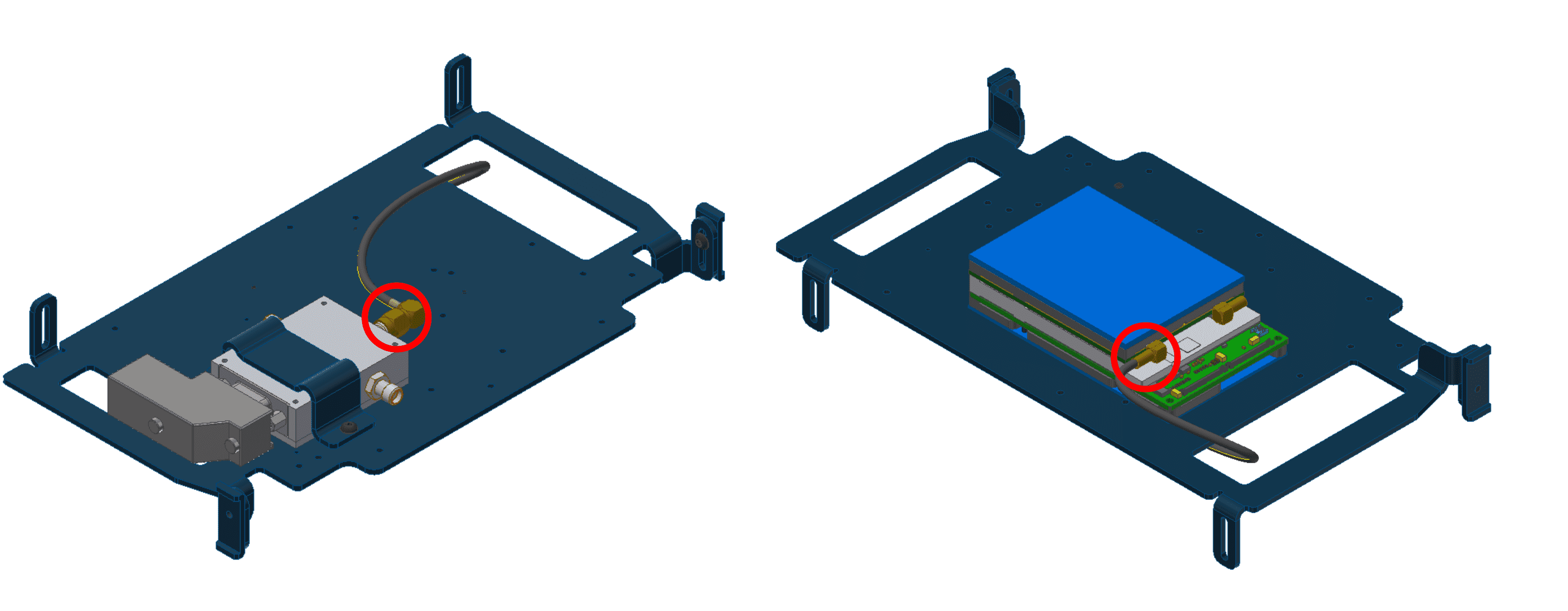
Hardware Silvus installation - Step 5
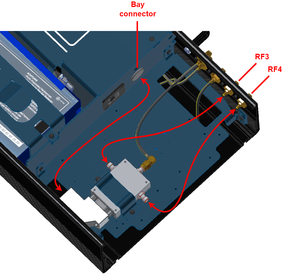
Place the plate in the PCS and connect the indicated modem connector to the RF2.

Hardware Silvus installation - Step 6
Connect the switch to bay connector, RF3 and RF4.
Hardware Silvus installation - Step 7
Attach the PCS to the pole according to Pole mount installation section of this manual (do not close the expansion bay yet).
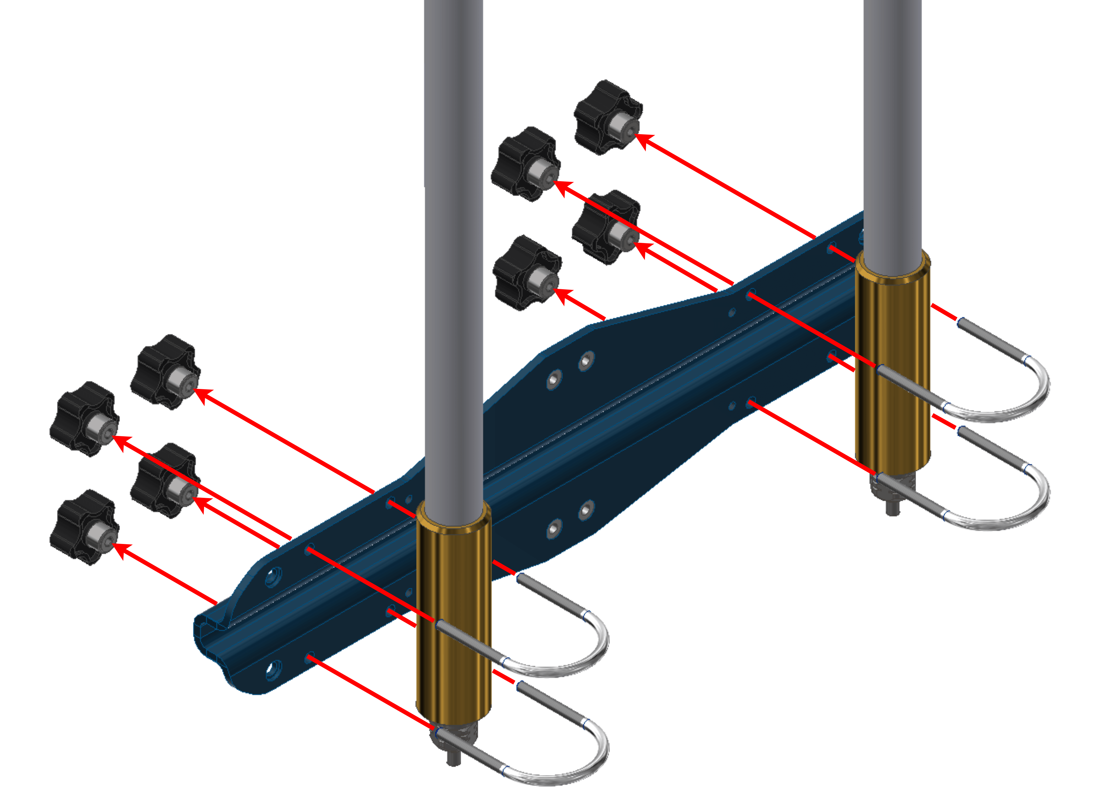
Fix both antennas to the holder with the knobs.
Important
If the user desires to tilt an antenna, ignore this step and read the Adjustable Antenna Mount section of this manual.
Hardware Silvus installation - Step 9
Join the holder to the pole with the wall bracket.

Hardware Silvus installation - Step 10
Wire the antennas. In case of using a Veronte T28 with the PCS, the wiring is different.
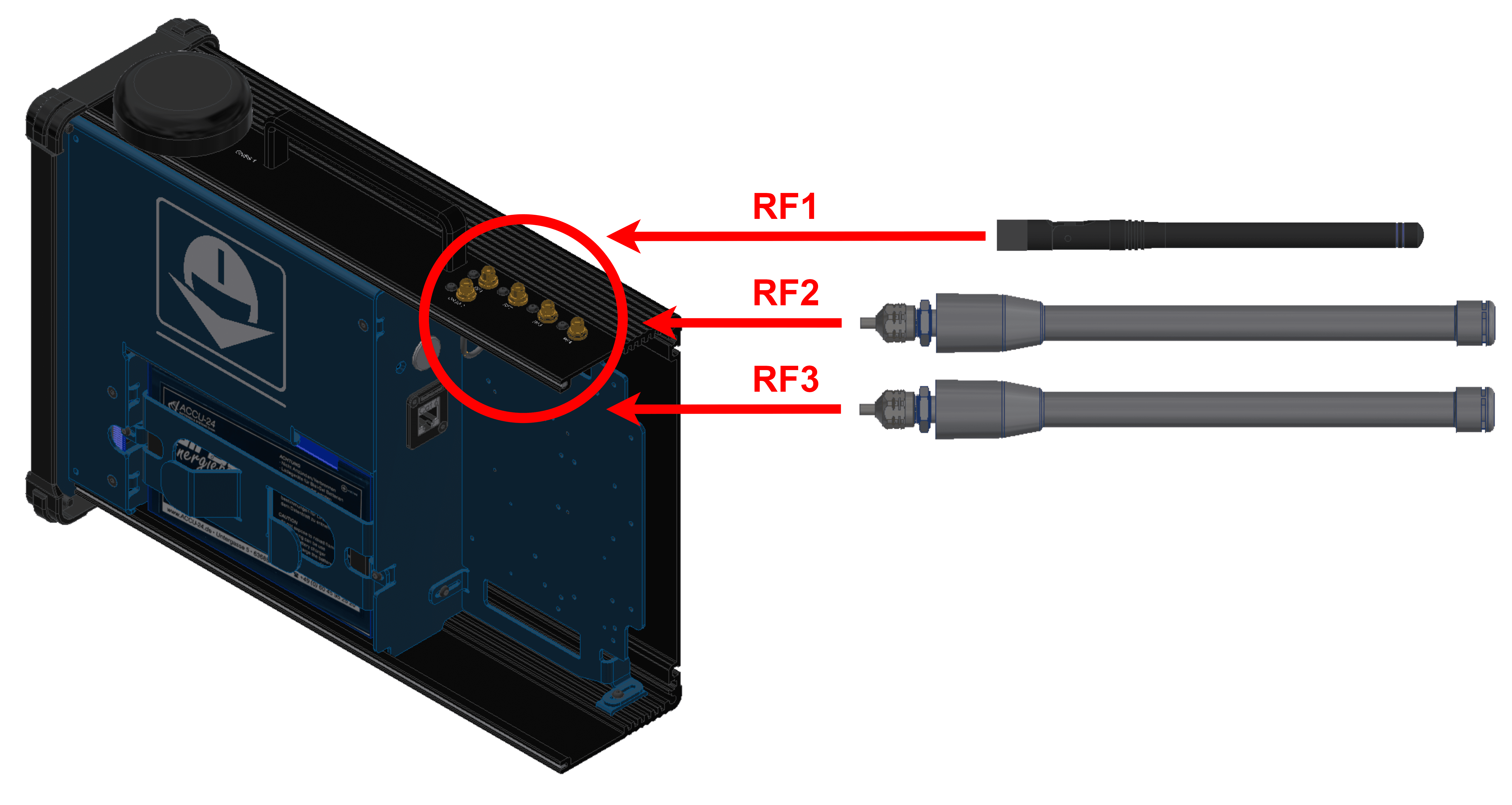
Wiring with only PCS
(Diagram not scaled)
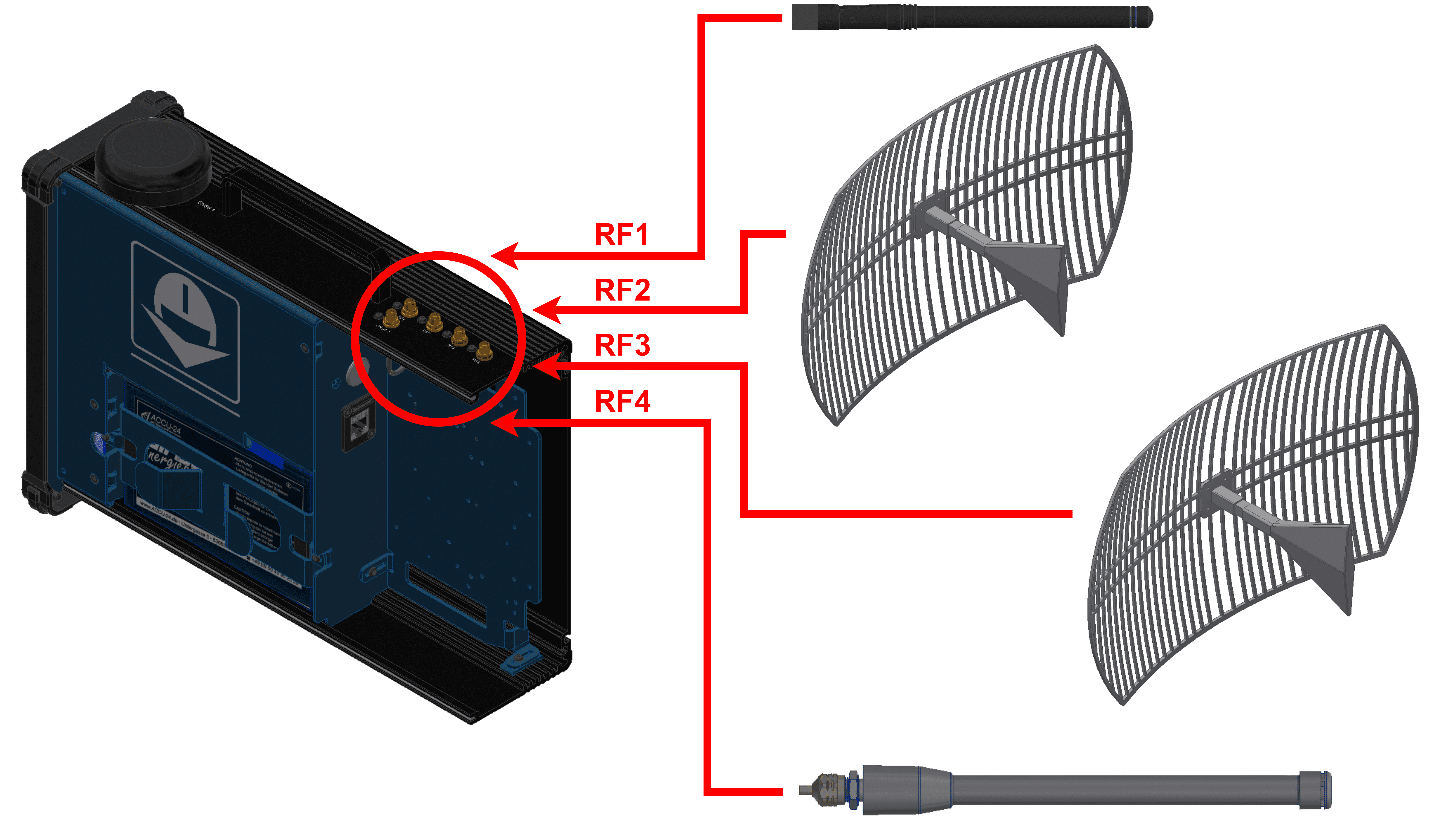
Wiring with PCS and T28
(Diagram not scaled)
Tip
Do not close the PCS until all configurations are finished.
Silvus radio configuration
To know how to do a basic configuration of the Silvus radio, visit Silvus radio configuration - Integration examples section of 1x Hardware Manual.
However, an additional configuration is required when working with a PCS instead of the GND unit of Veronte Autopilot 1x.
Networking. LAN Settings
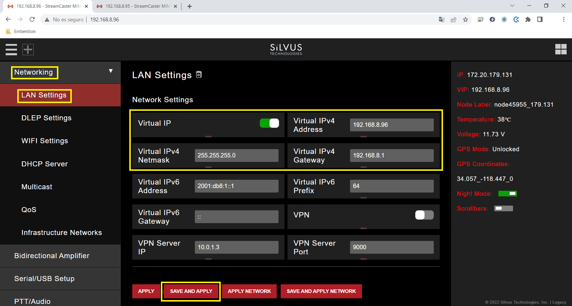
LAN Settings panel air unit
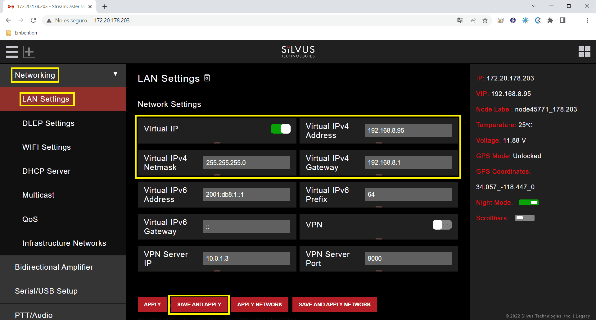
LAN Settings panel PCS
Virtual IP: Enable or Disable the Secondary IP address for the radio. Enable
Virtual IPv4 Address: Set the secondary IP address for the radio. The user can set any IP address, we have chosen 192.168.96 for the radio connected to the air unit and 192.168.95 for the radio linked to the PCS.
Virtual IPv4 Netmask: Netmask for the Secondary IP address, e.g. 255.255.255.0.
Virtual IPv4 Gateway: Gateway for local network to allow radio to connect to the internet. 192.168.8.1 is set because it is the IP address of the PCS router.
Silvus radio configuracion on PC
To be able to access the StreamScape GUI of the radios once connected to the PCS, check that the Network & Internet settings of the PC are as shown in the following screenshots.
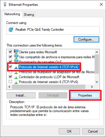
Ethernet settings 1
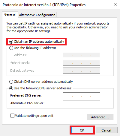
Ethernet settings 2
Note
This configuration is the same whether the PCS is connected via wifi or ethernet.
Silvus radio configuration in autopilot
To configure an Autopilot 1x for a Silvus radio, visit External radios - Integration examples section of 1x PDI Builder user manual.
