Hardware Installation
Mechanical Installation
Warning
Do not forget to connect RF antenna before powering up.
There are 2 separate accessories for the Veronte PCS in order to mount the unit on a mast, on the Veronte Tracker or a wall.
The accessories are :
-
Pole Mount:
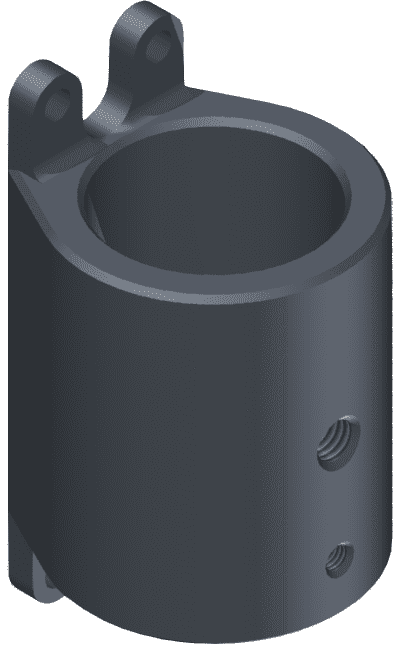
-
Wall Mount:
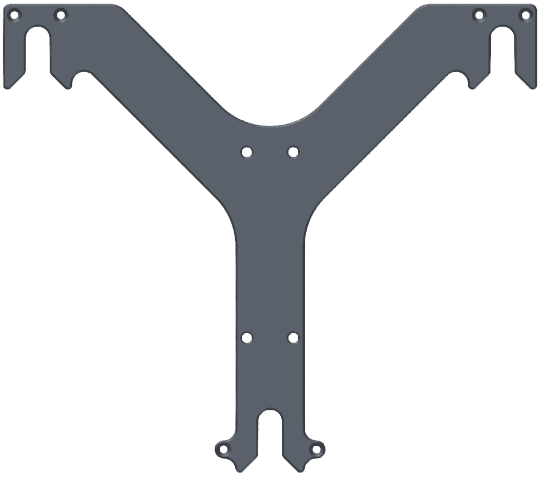
Pole Mount Installation
The pole mount is composed by two aluminun brackets to assemble the PCS to the foldable mast.
To assemble the system follow the next steps:
-
Attach the wall mount to the PCS Control Station.
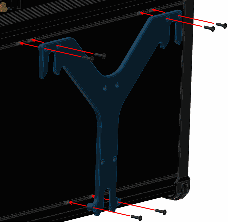
Pole Mount Installation - Step 1 -
Screw the pole mount against the wall mount with M5 allen screw driver.
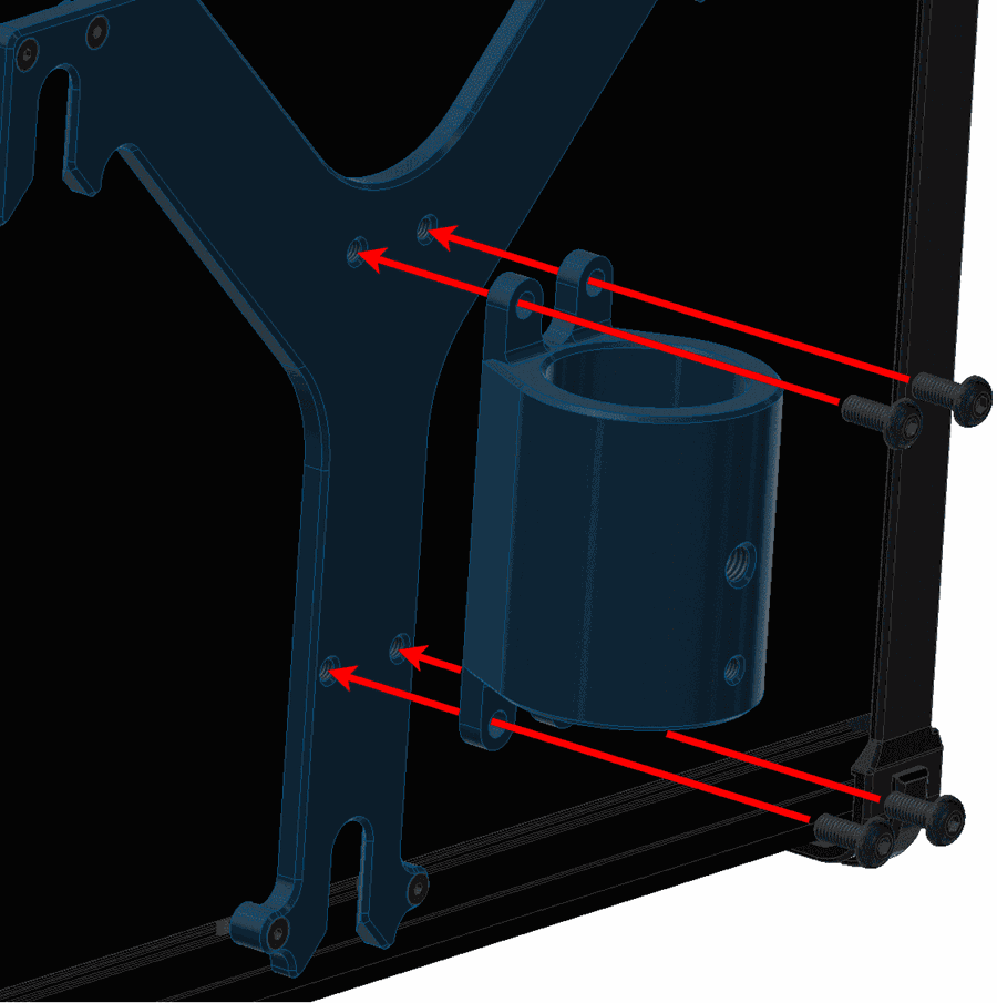
Pole Mount Installation - Step 2 -
Introduce the pole through the pole mount.
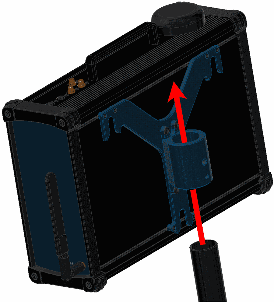
Pole Mount Installation - Step 3 -
Attach the ball chain to the pole mount with an M5 allen screw.
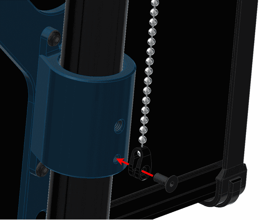
Pole Mount Installation - Step 4 -
Screw the wing knob against the pole mount to fix the pole.
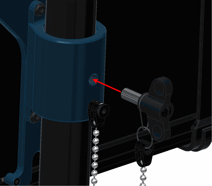
Pole Mount Installation - Step 5
Expansion Bay Access
This section explains how to access to the bay and adjust its position inside the PCS.
-
Remove the M5 allen screws and the frontal plate.
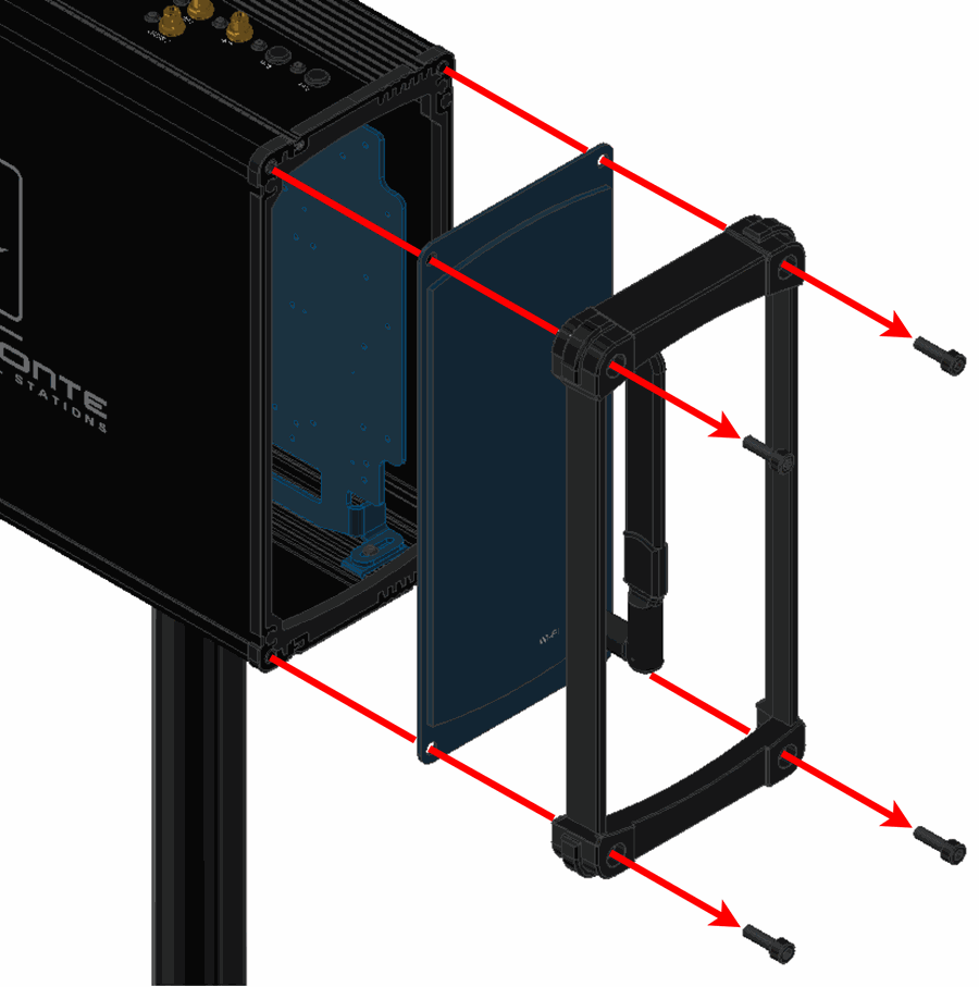
Expansion Bay Access - Step 1 -
At this point, the expansion bay is accessible.
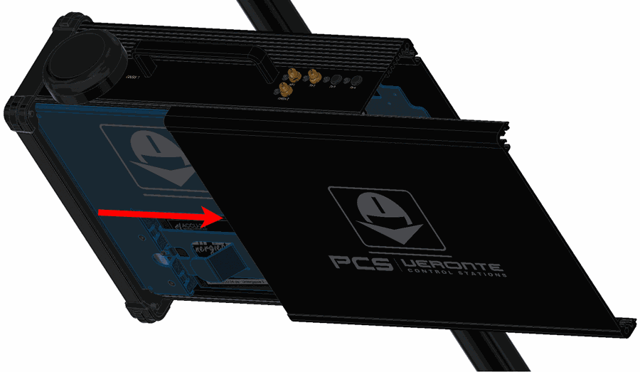
Expansion Bay Access - Step 2
Antenna Integration
The system uses different kinds of antenna to operate, they must be installed on the airframe. Here you can find some advice for obtaining the best performance and for avoiding antenna interferences.
Recommended specifications for GNSS antennas
| Specifications | Range |
|---|---|
| Antenna frequency L1 | 1561.098 MHz to 1602 MHz |
| Antenna frequency L2 | 1207.14 MHz to 1246 MHz |
| Amplifier gain | 17 dB to 35 dB |
| Out-of-band rejection | 40 dB
Note
Higher values are preferable. 30dB is considered the minimum acceptable value. |
| Polarization | RHCP (Right-Hand Circular Polarization) |
| Minimum supply voltage | 2.7 V to 3.3 V |
| Maximum supply current | 50 mA |
Electrical
Pinout
Main Connector pinout
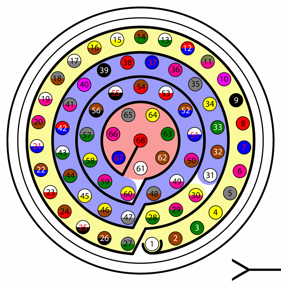
The 68 pin main connector has the distribution of input/output channels as follows:
Warning
Check the pin number before connecting. The color code is repeated 3 times due to the amount of pins. First section (yellow) corresponds to pins 1-30, the second section (blue) to pins 31-60 and the third one (red) to pins 61-68. Pin number increases counterclockwise following the black line of the picture above.
| PIN | Signal | Type | Description |
|---|---|---|---|
| 1 | I/O1 | I/O | PWM / Digital I/O signal (0-3.3V). Protected against ESD and short circuit. Maximum current: 1.65 mA |
| 2 | I/O2 | I/O | |
| 3 | I/O3 | I/O | |
| 4 | I/O4 | I/O | |
| 5 | I/O5 | I/O | |
| 6 | I/O6 | I/O | |
| 7 | I/O7 | I/O | |
| 8 | FTS_INT | Input | External FTS |
| 9 | GND | GROUND | Ground signal for actuators 1-8 |
| 10 | ETH_DB_P | I/O | Ethernet 1000Base |
| 11 | ETH_DB_N | I/O | |
| 12 | ETH_DA_P | I/O | |
| 13 | ETH_DA_N | I/O | |
| 14 | CHASSIS | I/O | Ethernet Chassis |
| 15 | CANFD_P | I/O | CAN FD |
| 16 | CANFD_N | I/O | |
| 17 | FTS_TX_OUT | Output | External FTS |
| 18 | GND (LED) | GROUND | LED Ground (Reserved) |
| 19 | BAT (BUTTON) | Output | On Connector (Reserved)t |
| 20 | SYS_ON_CN (BUTTON) | Input | On Connector (Reserved) |
| 21 | ETH_DC_P | I/O | Ethernet 1000Base |
| 22 | Analog 4 | Input Analog | Input 0-3.3V. Protected against ESD and short circuit |
| 23 | 5V (LED) | Output | LED Supply (Reserved) |
| 24 | ETH_DC_N | I/O | Ethernet 1000Base |
| 25 | CANA_P | I/O | CANbus interface, up to 1Mbps (2.3V Typical, 1.2V-2.3V Differential). Protected against ESD |
| 26 | CANA_N | I/O | Twisted pair with a 120 ohms Zo recommended (2.3V Typical, 1.2V-2.3V Differential). Protected against ESD |
| 27 | 24V_OUT | Output | 24 Power Output |
| 28 | CANB_P | I/O | CANbus interface. It supports data rates up to 1 Mbps. Protected against ESD |
| 29 | CANB_N | I/O | Twisted pair with a 120 ohms Zo recommended. Protected against ESD |
| 30 | ETH_DD_P | I/O | Ethernet 1000Base |
| 31 | I2C_CLK | Output | Clk line for I2C bus (0.3V to 3.3V). Protected against ESD and short circuit |
| 32 | I2C_DATA | I/O | Data line for I2C bus (0.3V to 3.3V). Protected against ESD and short circuit |
| 33 | GND | GROUND | Ground for 3.3V power supply |
| 34 | 3.3V | POWER | 3.3V - 100mA power supply. Protected against ESD short circuit with 100mA resettable fuse |
| 35 | GND | GROUND | Ground for 5V power supply |
| 36 | 5V | POWER | 5V – 100mA power supply. Protected against ESD short circuit with 100mA resettable fuse |
| 37 | GND | GROUND | Ground for analog signals |
| 38 | ANALOG_1 | Input | Analog input 0-3.3V. Protected against ESD and short circuit |
| 39 | ANALOG_2 | Input | Analog input 0-3.3V. Protected against ESD and short circuit |
| 40 | ANALOG_3 | Input | Analog input 0-3.3V. Protected against ESD and short circuit |
| 41 | ETH_DD_N | I/O | Ethernet 1000Base |
| 42 | FTS1_OUT | Output | Deadman signal from comicro. Protected against ESD and short circuit |
| 43 | FTS2_OUT | Output | !SystemOK Bit. Protected against ESD and short circuit |
| 44 | 12V_OUT | Output | 12V Power Output |
| 45 | RS232_B_TX | Output | RS-232 |
| 46 | RS232_B_RX | Input | RS-232 |
| 47 | GND | GROUND | Ground signal comicro power supply |
| 48 | VCC | POWER | Power supply (14 to 24V). Protected against reverse polarity |
| 49 | GND | GND | Ground |
| 50 | RS485_A_TX_P | Output |
Warning
RS-485 bus is used by default by the autopilot for ethernet communications (and consequently wifi). Do not connect these pins unless it is asked to [email protected]. |
| 51 | RS485_A_TX_N | Output | |
| 52 | RS485_A_RX_N | Input | |
| 53 | RS485_A_RX_P | Input | |
| 54 | RS485_GND | GND | |
| 55 | 12V_OUT | Output | 12V Power Output |
| 56 | 24V_OUT | Output | 24V Power Output |
| 57 | EQEP_S | I/O | DIGITAL output / DIGITAL input / Encoder strobe input (0-3.3V). Protected against ESD and short circuit |
| 58 | EQEP_I | I/O | DIGITAL output / DIGITAL input / Encoder index input A (0-3.3V). Protected against ESD and short circuit |
| 59 | GND | GROUND | Ground for encoders |
| 60 | RS485_B_TX_P | Output | RS-485 B Full-Duplex |
| 61 | RS485_B_TX_N | Output | RS-485 B Full-Duplex |
| 62 | RS485_B_RX_N | Input | RS-485 B Full-Duplex |
| 63 | RS485_B_RX_P | Input | RS-485 B Full-Duplex/ |
| 64 | FTS_TX_IN | Input | External FTS |
| 65 | GND | GROUND | Veronte ground input |
| 66 | GND | GROUND | Veronte ground input |
| 67 | VCC | POWER | Power supply (14V to 24V). Protected against reverse polarity |
| 68 | VCC | POWER |
Note
The functions marked with (*) differ from Veronte Autopilot 1x Pinout
Warning
- All GND pins are common.
- Pins 27, 67 and 68 are common. Connect them to the same power supply voltage.
- CAN Interfaces have configurable internal termination resistors. However, users should also be aware that depending on the 1x unit inside the PCS, this resistance may or may not be enabled by default.
Expansion Bay Connector pinout
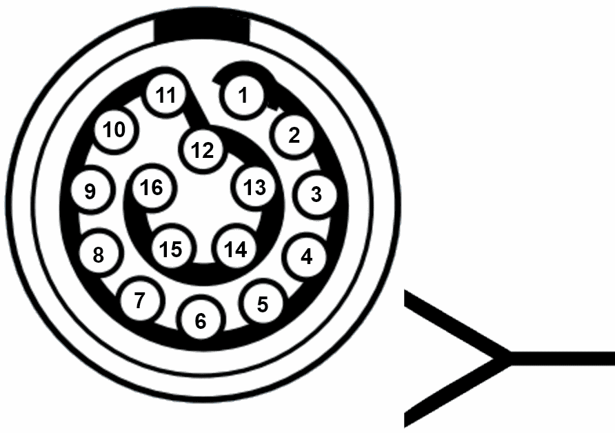
| PIN | Signal | Type | Description |
|---|---|---|---|
| 1 | 3.3 V | Output | Output power supply. Maximum current: 5 A. |
| 2 | GND | GROUND | Ground. Maximum current: 6 A. |
| 3 | 5 V | Output | Output power supply. Maximum current: 5 A. |
| 4 | GND | GROUND | Ground. Maximum current: 6 A. |
| 5 | 12 V | Output | Output power supply. Maximum current: 6 A. |
| 6 | GND | GROUND | Ground. Maximum current: 6 A. |
| 7 | 24 V | Output | Output power supply. Maximum current: 6 A. |
| 8 | GND | GROUND | Ground. Maximum current: 6 A.
Warning
This pin has a different maximum current. |
| 9 | FTS_RX | Input | FTS RS232 RX (-13.2V to 13.2V Max, -5.4V to 5.4V Typical) |
| 10 | FTS_TX | Output | FTS RS232 TX (-13.2V to 13.2V Max, -5.4V to 5.4V Typical). |
| 11 | GND | GROUND | FTS Ground |
| 12 | PPM | Input | Pin for PPM signal (EQEP_A). |
| 13 | CANA_P | I/O | CAN 2.0 Interface, up to 1Mbps (2.3V to 3V Typical). |
| 14 | RS 232-TX | Output | RS 232 Output (-13.2V to 13.2V Max, -5.4V to 5.4V Typical).
Warning
This pin is common with the external pinout. |
| 15 | CANA_N | I/O | CAN 2.0 Interface up to 1Mbps (1V to 2.3V Typical). |
| 16 | RS 232-RX | Input | RS 232 Input (-13.2V to 13.2V Max, -5.4V to 5.4V Typical).
Warning
This pin is common with the external pinout. |
Harnesses
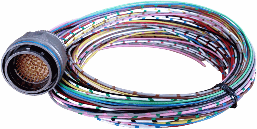
A wire harness is a structured assembly of cables and connectors used to organize and manage wiring in electrical and electronic systems. It is designed to ensure a tidy and secure installation of cables, preventing tangles, electromagnetic interference, and facilitating maintenance.
Veronte PCS 2.2 has two compatible harnesses:
| Veronte Harness Blue 68P | Veronte Control Stations: Conn Harness PCS 2.2 |
|---|---|
 |
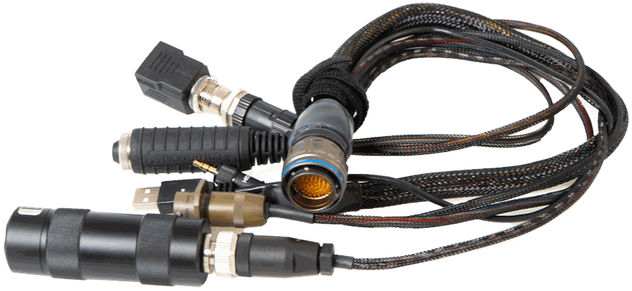 |
| Harness available on demand with the Embention reference P001114 | Harness available on demand with the Embention reference P014932 |
Dimensions
- Harness Blue 68P wire gauge: 22 AWG
- Cables lenght: 52 cm
-
Harness plug dimensions:
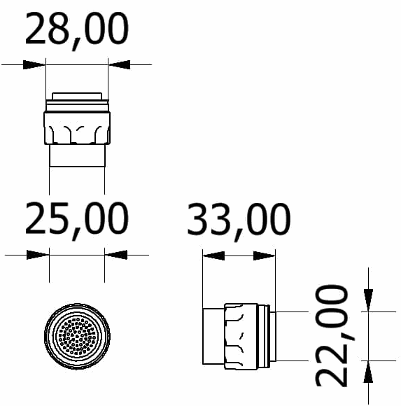
Connector FGW.LM.368.XLCT dimensions (cm)
Pinout

Veronte Harness Blue 68P
The pinout of the Veronte Harness Blue 68P is the same as the Main Connector pinout above. The color code of the harness wires is given below.
Warning
Check the pin number before connecting. The colour code is repeated 3 times due to the amount of pins. First section (yellow) corresponds to pins 1-30, the second section (blue) to pins 31-60 and the third one (red) to pins 61-68. Pin number increases following the black line of the pictures above: counterclockwise for the connector and clockwise for the plug.
| PIN | Color Code | PIN | Color Code |
|---|---|---|---|
| 1 | White | 35 | Gray |
| 2 | Brown | 36 | Pink |
| 3 | Green | 37 | Blue |
| 4 | Yellow | 38 | Red |
| 5 | Gray | 39 | Black |
| 6 | Pink | 40 | Violet |
| 7 | Blue | 41 | Gray - Pink |
| 8 | Red | 42 | Red - Blue |
| 9 | Black | 43 | White - Green |
| 10 | Violet | 44 | Brown - Green |
| 11 | Gray - Pink | 45 | White - Yellow |
| 12 | Red - Blue | 46 | Yellow - Brown |
| 13 | White - Green | 47 | White - Gray |
| 14 | Brown - Green | 48 | Gray - Brown |
| 15 | White - Yellow | 49 | White - Pink |
| 16 | Yellow - Brown | 50 | Pink - Brown |
| 17 | White - Gray | 51 | White - Blue |
| 18 | Gray - Brown | 52 | Brown - Blue |
| 19 | White - Pink | 53 | White - Red |
| 20 | Pink - Brown | 54 | Brown - Red |
| 21 | White - Blue | 55 | White - Black |
| 22 | Brown - Blue | 56 | Brown - Black |
| 23 | White - Red | 57 | Gray - Green |
| 24 | Brown - Red | 58 | Yellow - Green |
| 25 | White - Black | 59 | Pink - Green |
| 26 | Brown - Black | 60 | Yellow - Pink |
| 27 | Gray - Green | 61 | White |
| 28 | Yellow - Green | 62 | Brown |
| 29 | Pink - Green | 63 | Green |
| 30 | Yellow - Pink | 64 | Yellow |
| 31 | White | 65 | Gray |
| 32 | Brown | 66 | Pink |
| 33 | Green | 67 | Blue |
| 34 | Yellow | 68 | Red |
Veronte Control Stations: Conn Harness PCS 2.2
The pinout of this harness is the same as the Main Connector pinout above. In addition, this harness has some connectors already implemented for easy operation. Below is detailed information on which pins these connectors are connected to:
| Connector | PIN | Signal |
|---|---|---|
| Power | 48 | VCC |
| 47 | GND | |
| 65 | GND | |
| 66 | GND | |
| 67 | VCC | |
| 68 | VCC | |
| ON/OFF Button | 23 | 5V |
| 49 | GND | |
| 55 | BAT | |
| 56 | SYS_ON_CN | |
| FTS Connector | 8 | FTS_INT |
| 36 | 5V_BUS | |
| 64 | FTS_TX_IN | |
| 17 | FTS_TX_OUT | |
| Maintenance Button | 31 | I2C_CLK |
| 32 | I2C_DATA | |
| Jack Connector | 18 | GND |
| 57 | EQEP_S | |
| Ethernet Connector | 21 | TX+ ETH |
| 24 | TX- ETH | |
| 30 | RX+ ETH | |
| 41 | RX- ETH |
Warning
Do NOT connect the CS harness provided for other Veronte units. ONLY use PCS own Mating connector.
Ethernet Internal Device Connection
PCS bay has an Ethernet connection fully isolated from the external connector. It is normally used for interconnection with video RF links. It can be used for any other device to integrate into the PCS.
© 2026 Embention. All rights reserved.