Hardware Installation
Pinout
Main Connector
The 68 pin main connector has the distribution of input/output channels as follows:
PCS Harness connector
PCS Unit - Input pins
Pin |
Signal |
Type |
Comments |
|---|---|---|---|
1 |
I/O1 |
I/O |
PWM / Digital I/O signal (0-3.3V). Protected against ESD and short circuit. Maximum current: 1.65 mA |
2 |
I/O2 |
I/O |
PWM / Digital I/O signal (0-3.3V). Protected against ESD and short circuit. Maximum current: 1.65 mA |
3 |
I/O3 |
I/O |
PWM / Digital I/O signal (0-3.3V). Protected against ESD and short circuit. Maximum current: 1.65 mA |
4 |
I/O4 |
I/O |
PWM / Digital I/O signal (0-3.3V). Protected against ESD and short circuit. Maximum current: 1.65 mA |
5 |
I/O5 |
I/O |
PWM / Digital I/O signal (0-3.3V). Protected against ESD and short circuit. Maximum current: 1.65 mA |
6 |
I/O6 |
I/O |
PWM / Digital I/O signal (0-3.3V). Protected against ESD and short circuit. Maximum current: 1.65 mA |
7 |
I/O7 |
I/O |
PWM / Digital I/O signal (0-3.3V). Protected against ESD and short circuit. Maximum current: 1.65 mA |
8 |
I/O8 |
I/O |
PWM / Digital I/O signal (0-3.3V). Protected against ESD and short circuit. Maximum current: 1.65 mA |
9 |
GND |
GROUND |
Ground signal for actuators 1-8 |
10 |
I/O9 |
I/O |
PWM / Digital I/O signal (0-3.3V). Protected against ESD and short circuit. Maximum current: 1.65 mA |
11 |
I/10 |
I/O |
PWM / Digital I/O signal (0-3.3V). Protected against ESD and short circuit. Maximum current: 1.65 mA |
12 |
I/11 |
I/O |
PWM / Digital I/O signal (0-3.3V). Protected against ESD and short circuit. Maximum current: 1.65 mA |
13 |
I/12 |
I/O |
PWM / Digital I/O signal (0-3.3V). Protected against ESD and short circuit. Maximum current: 1.65 mA |
14 |
I/13 |
I/O |
PWM / Digital I/O signal (0-3.3V). Protected against ESD and short circuit. Maximum current: 1.65 mA |
15 |
I/14 |
I/O |
PWM / Digital I/O signal (0-3.3V). Protected against ESD and short circuit. Maximum current: 1.65 mA |
16 |
I/15 |
I/O |
PWM / Digital I/O signal (0-3.3V). Protected against ESD and short circuit. Maximum current: 1.65 mA |
17 |
I/16 |
I/O |
PWM / Digital I/O signal (0-3.3V). Protected against ESD and short circuit. Maximum current: 1.65 mA |
18 |
GND |
GROUND |
Ground signal for actuators 9-16 |
19 |
RS 232 TX |
Output |
RS 232 Output (-13.2V to 13.2V Max, -5.4V to 5.4V Typical). Protected against ESD and short circuit |
20 |
RS 232 RX |
Input |
RS 232 Input (-25V to 25V Max, -0.6V Low and 2.4V High Threshold). Protected against ESD and short circuit |
21 |
Tx+ (*) |
Output |
Ethernet transmitter positive |
22 |
Analog 4 |
Input Analog |
Input 0-3.3V. Protected against ESD and short circuit |
23 |
No connect(*) |
Input Analog |
Input 0-3.3V. Protected against ESD and short circuit |
24 |
Tx- (*) |
Output |
Ethernet transmitter negative |
25 |
CanA P |
I/O |
CANbus interface, up to 1Mbps (2.3V Typical, 1.2V-2.3V Differential). Protected against ESD |
26 |
CanA N |
I/O |
Twisted pair with a 120 ohms Zo recommended (2.3V Typical, 1.2V-2.3V Differential). Protected against ESD |
27 |
24V (*) |
Output |
Power supply. Common with pin 44 |
28 |
CANB_P |
I/O |
CANbus interface. It supports data rates up to 1 Mbps. Protected against ESD |
29 |
CANB_N |
I/O |
Twisted pair with a 120 ohms Zo recommended. Protected against ESD |
30 |
Rx+ (*) |
Input |
Ethernet receiver positive |
31 |
I2C_CLK |
Output |
Clk line for I2C bus (0.3V to 3.3V). Protected against ESD and short circuit |
32 |
I2C_DATA |
I/O |
Data line for I2C bus (0.3V to 3.3V). Protected against ESD and short circuit |
33 |
GND |
GROUND |
Ground for 3.3V power supply |
34 |
3.3V |
POWER |
3.3V - 100mA power supply. Protected against ESD short circuit with 100mA resettable fuse |
35 |
GND |
GROUND |
Ground for 5V power supply |
36 |
5V |
POWER |
5V – 100mA power supply. Protected against ESD short circuit with 100mA resettable fuse |
37 |
GND |
GROUND |
Ground for analog signals |
38 |
ANALOG_1 |
Input |
Analog input 0-3.3V. Protected against ESD and short circuit |
39 |
ANALOG_2 |
Input |
Analog input 0-3.3V. Protected against ESD and short circuit |
40 |
ANALOG_3 |
Input |
Analog input 0-3.3V. Protected against ESD and short circuit |
41 |
RX- (*) |
I/O |
Ethernet receiver negative |
42 |
FTS1_OUT |
Output |
Deadman signal from comicro. Protected against ESD and short circuit |
43 |
FTS2_OUT |
Output |
!SystemOK Bit. Protected against ESD and short circuit |
44 |
24V (*) |
Output |
Power supply. Common with pin 27 |
45 |
UARTA_TX |
Output |
Microcontroller UART |
46 |
UARTA_RX |
Input |
Microcontroller UART |
47 |
GND |
GROUND |
Ground signal comicro power supply |
48 |
VCC (*) |
POWER |
Power supply (14 to 24V). Protected against reverse polarity |
49 |
GND (*) |
GND |
Ground |
50 |
OUT_RS485_P |
Output |
Non-inverted output from RS485 bus (-7V to 12V Max, -2.3V to 2.3V Typical). Protected against ESD and short circuit |
51 |
OUT_RS485_N |
Output |
Inverted output from RS485 bus (-7V to 12V Max, -2.3V to 2.3V Typical). Protected against ESD and short circuit |
52 |
IN_RS845_N |
Input |
Inverted input from RS485 bus (-7V to 12V Max, -2.3V to 2.3V Typical). Protected against ESD and short circuit |
53 |
IN_RS845_P |
Input |
Non-inverted output from RS485 bus (-7V to 12V Max, -2.3V to 2.3V Typical). Protected against ESD and short circuit |
54 |
RS-485_GND |
GND |
Ground for RS-485 bus |
55 |
No connect(*) |
/ |
/ |
56 |
No connect(*) |
/ |
/ |
57 |
EQEP_S |
I/O |
DIGITAL output / DIGITAL input / Encoder strobe input (0-3.3V). Protected against ESD and short circuit |
58 |
EQEP_I |
I/O |
DIGITAL output / DIGITAL input / Encoder index input A (0-3.3V). Protected against ESD and short circuit |
59 |
GND |
GROUND |
Ground for encoders |
60 |
V_USB_DP |
I/O |
Veronte USB data line. Protected against ESD |
61 |
V_USB_DN |
I/O |
Veronte USB data line. Protected against ESD |
62 |
USB_GND (GND) |
GROUND |
USB ground |
63 |
No connect(*) |
/ |
/ |
64 |
No connect(*) |
/ |
/ |
65 |
GND |
GROUND |
Veronte ground input |
66 |
GND |
GROUND |
Veronte ground input |
67 |
VCC |
POWER |
Power supply (14V to 24V). Protected against reverse polarity |
68 |
VCC |
POWER |
Note
The functions marked with (*) differ from Veronte Autopilot 1x Pinout
Warning
All GND pins are common.
Pins 27, 67 and 68 are common. Connect them to the same power supply voltage.
RS-485 bus is used by default by the Veronte BCS for Ethernet communications.
CANA and CANB buses do not have termination resistor, user should add them based on its own wiring design.
Connector colour code:
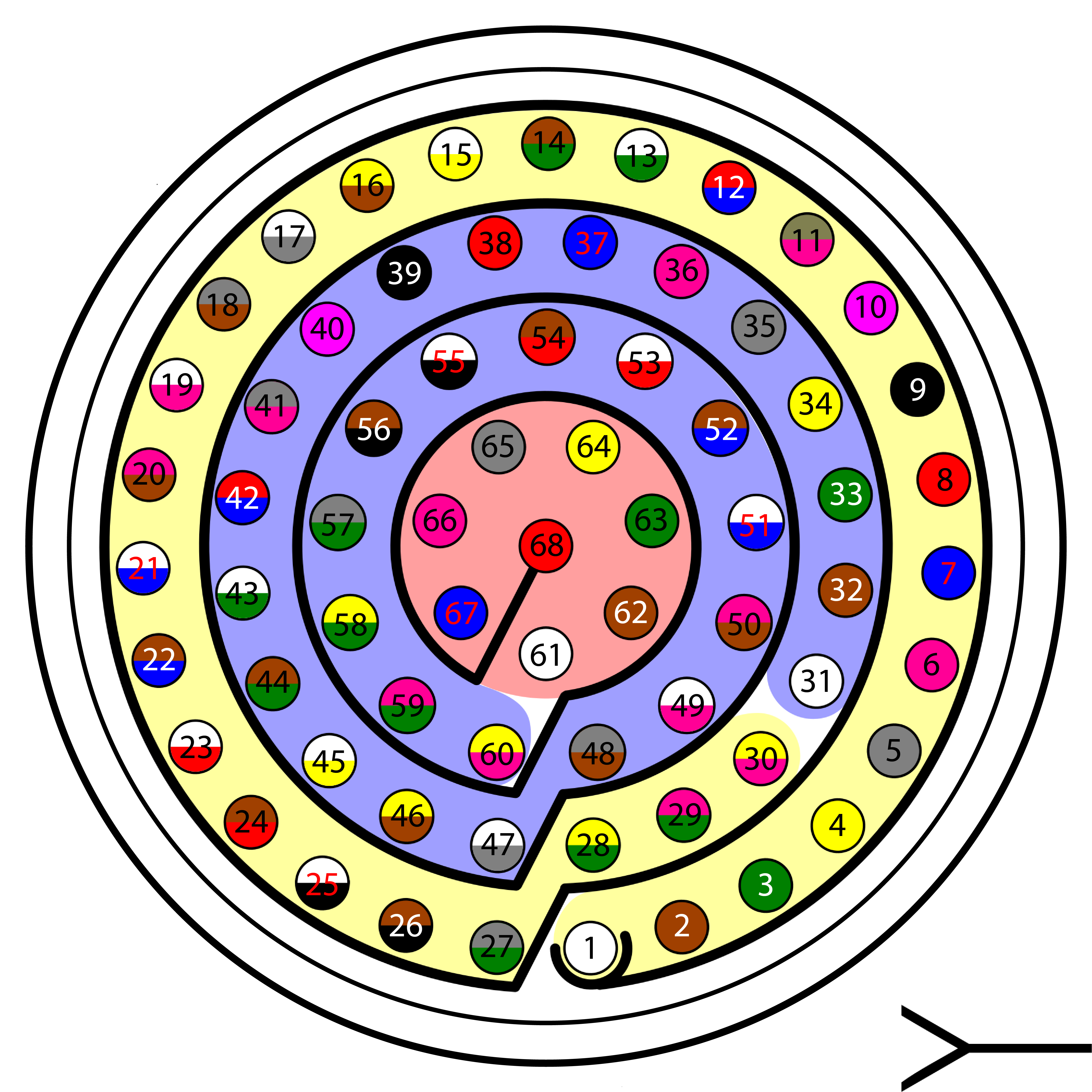
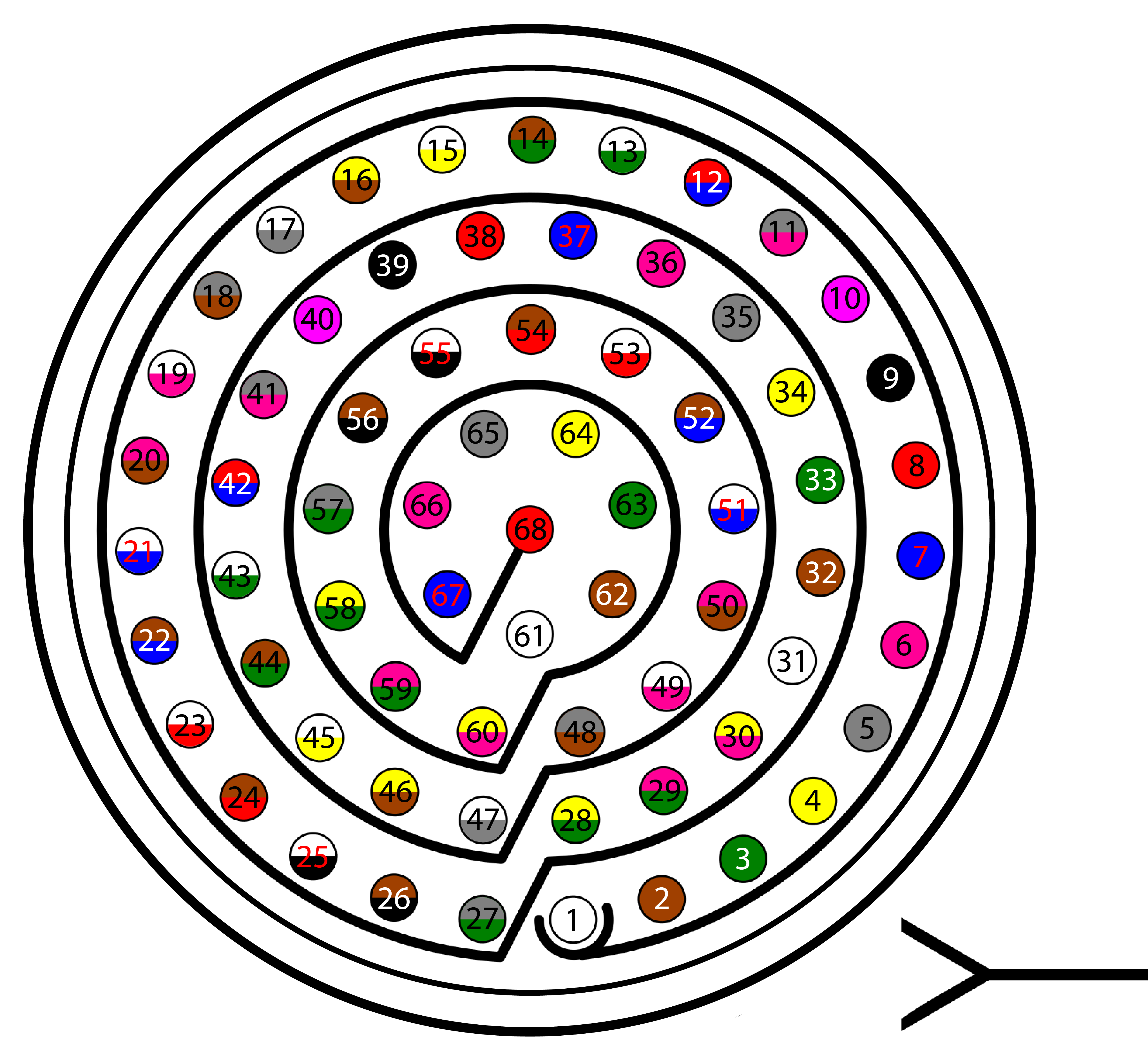
Connector HEW.LM.368.XLNP
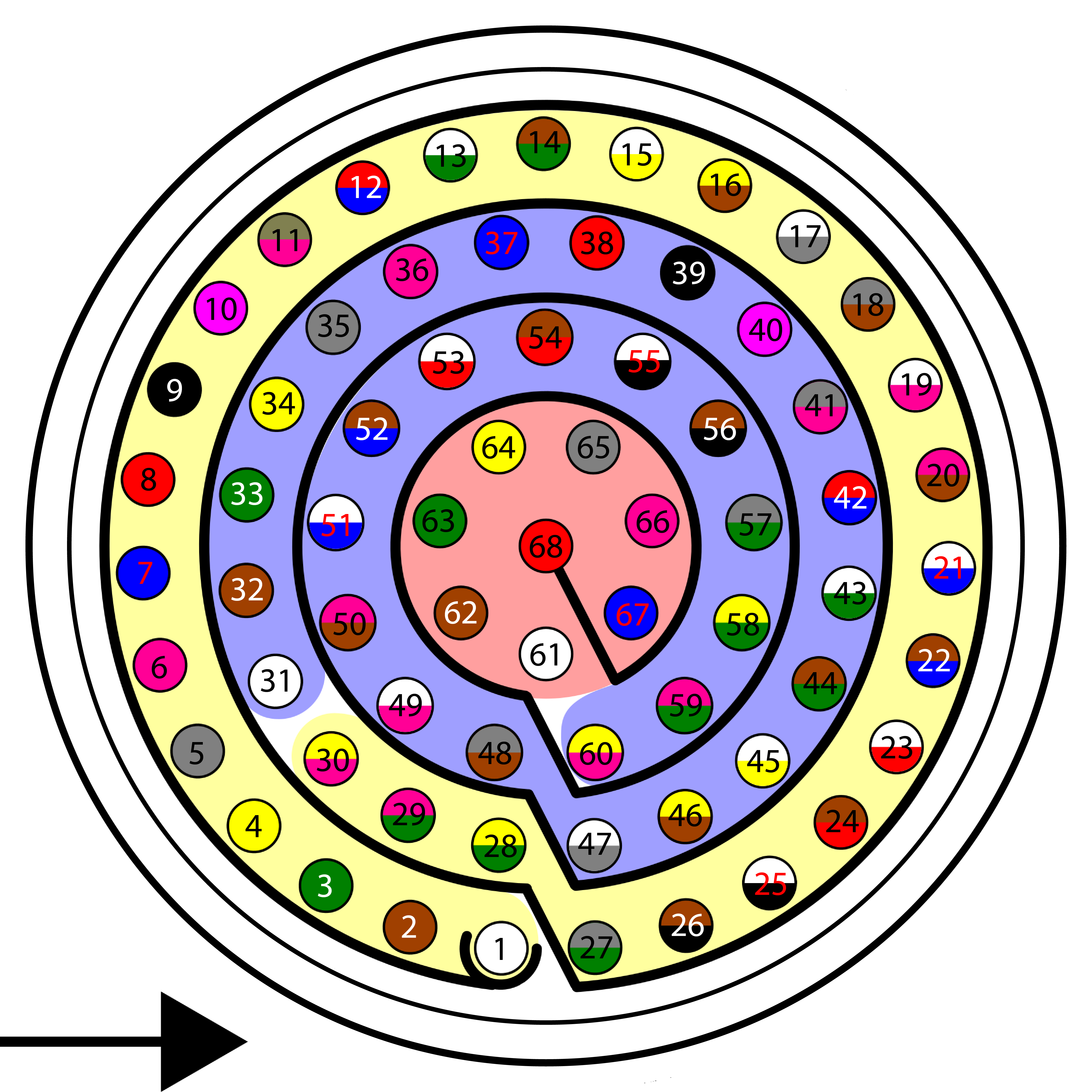
Harness plug
Warning
Check the pin number before connecting. The colour code is repeated 3 times due to the amount of pins. First section (yellow) corresponds to pins 1-30, the second section (blue) to pins 31-60 and the third one (red) to pins 61-68. Pin number increases following the black line of the pictures above: counterclockwise for the connector and clockwise for the plug.
PIN |
Color code |
PIN |
Color code |
|---|---|---|---|
1 |
White |
35 |
Gray |
2 |
Brown |
36 |
Pink |
3 |
Green |
37 |
Blue |
4 |
Yellow |
38 |
Red |
5 |
Gray |
39 |
Black |
6 |
Pink |
40 |
Violet |
7 |
Blue |
41 |
Gray – Pink |
8 |
Red |
42 |
Red – Blue |
9 |
Black |
43 |
White – Green |
10 |
Violet |
44 |
Brown – Green |
11 |
Gray – Pink |
45 |
White – Yellow |
12 |
Red – Blue |
46 |
Yellow – Brown |
13 |
White – Green |
47 |
White – Gray |
14 |
Brown – Green |
48 |
Gray – Brown |
15 |
White – Yellow |
49 |
White – Pink |
16 |
Yellow – Brown |
50 |
Pink – Brown |
17 |
White – Gray |
51 |
White – Blue |
18 |
Gray – Brown |
52 |
Brown – Blue |
19 |
White – Pink |
53 |
White – Red |
20 |
Pink – Brown |
54 |
Brown – Red |
21 |
White – Blue |
55 |
White – Black |
22 |
Brown – Blue |
56 |
Brown – Black |
23 |
White – Red |
57 |
Gray – Green |
24 |
Brown – Red |
58 |
Yellow – Green |
25 |
White – Black |
59 |
Pink – Green |
26 |
Brown – Black |
60 |
Yellow – Pink |
27 |
Grey – Green |
61 |
White |
28 |
Yellow – Green |
62 |
Brown |
29 |
Pink – Green |
63 |
Green |
30 |
Yellow – Pink |
64 |
Yellow |
31 |
White |
65 |
Grey |
32 |
Brown |
66 |
Pink |
33 |
Green |
67 |
Blue |
34 |
Yellow |
68 |
Red |
Expansion Bay Connector

Expansion Bay Connector
PCS Unit - Output pins
Pin |
Signal |
Type |
Comments |
|---|---|---|---|
1 |
3.3 V |
Output |
Output power supply. Maximum current: 4 A. |
2 |
GND |
GROUND |
Ground. Maximum current: 4 A. |
3 |
5 V |
Output |
Output power supply. Maximum current: 4 A. |
4 |
GND |
GROUND |
Ground. Maximum current: 4 A. |
5 |
12 V |
Output |
Output power supply. Maximum current: 4 A. |
6 |
GND |
GROUND |
Ground. Maximum current: 4 A. |
7 |
24 V |
Output |
Output power supply. Maximum current: 4 A. |
8 |
GND |
GROUND |
Ground. Maximum current: 4 A. |
9 |
No connect |
/ |
/ |
10 |
|||
11 |
|||
12 |
|||
13 |
CanA P |
I/O |
CANbus interface, up to 1Mbps (2.3V Typical, 1.2V-2.3V Differential). |
14 |
RS 232 TX |
Output |
RS 232 Output (-13.2V to 13.2V Max, -5.4V to 5.4V Typical). |
15 |
CanA N |
I/O |
Twisted pair with a 120 ohms Zo recommended (2.3V Typical, 1.2V-2.3V Differential). |
16 |
RS 232 RX |
Input |
RS 232 Input (-25V to 25V Max, -0.6V Low and 2.4V High Threshold). |
Warning
RS-232 pins are common with the external pinnout.
Mechanical installation
There are 2 separate accessories for the Veronte PCS in order to mount the unit on a mast, on the Veronte Tracker or a wall.
The accessories are :
Pole Mount.
Pole mount
Wall Mount
Wall mount
The installation of the wall mount is described in the Veronte Tracker Manual.
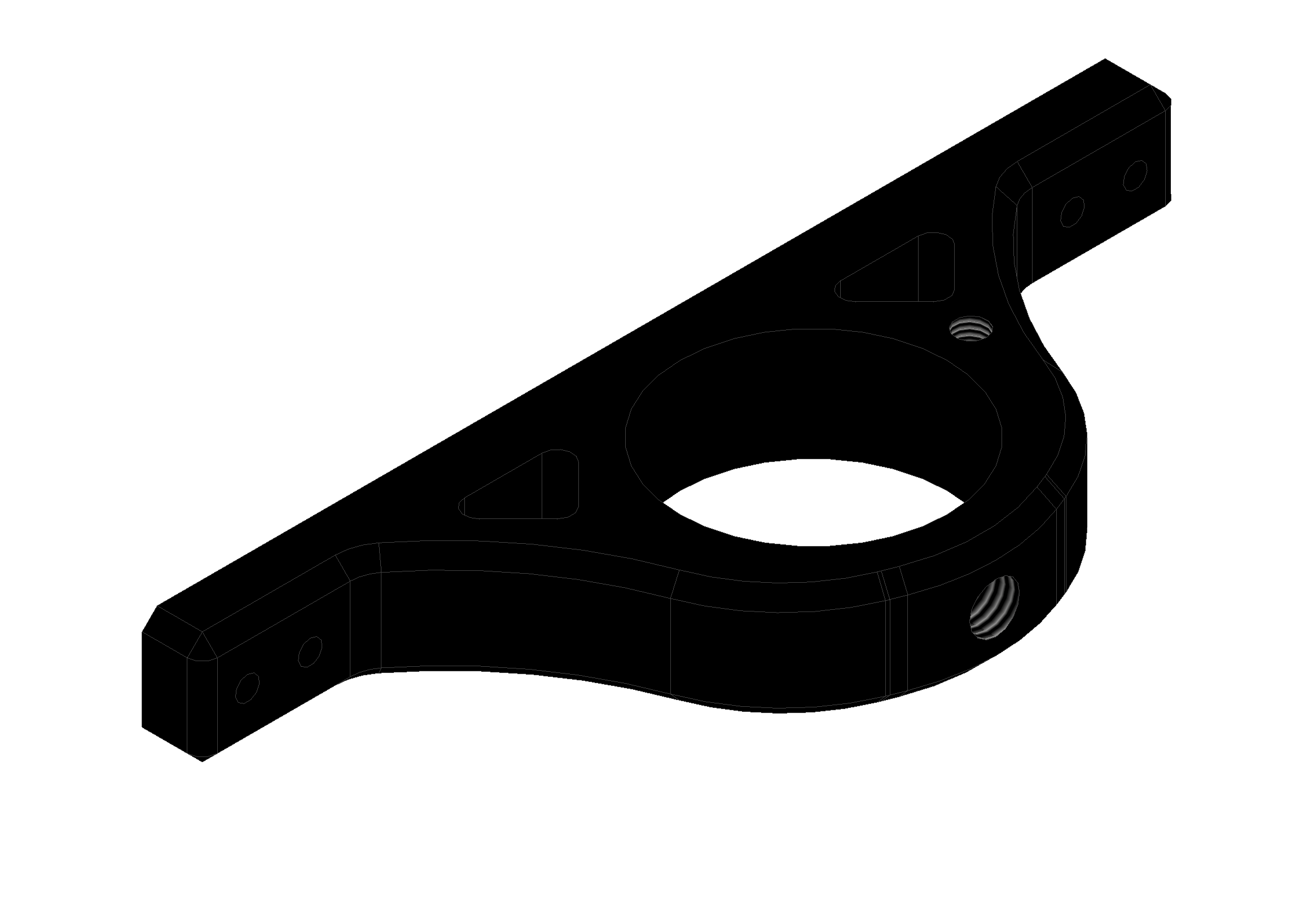
Pole mount installation
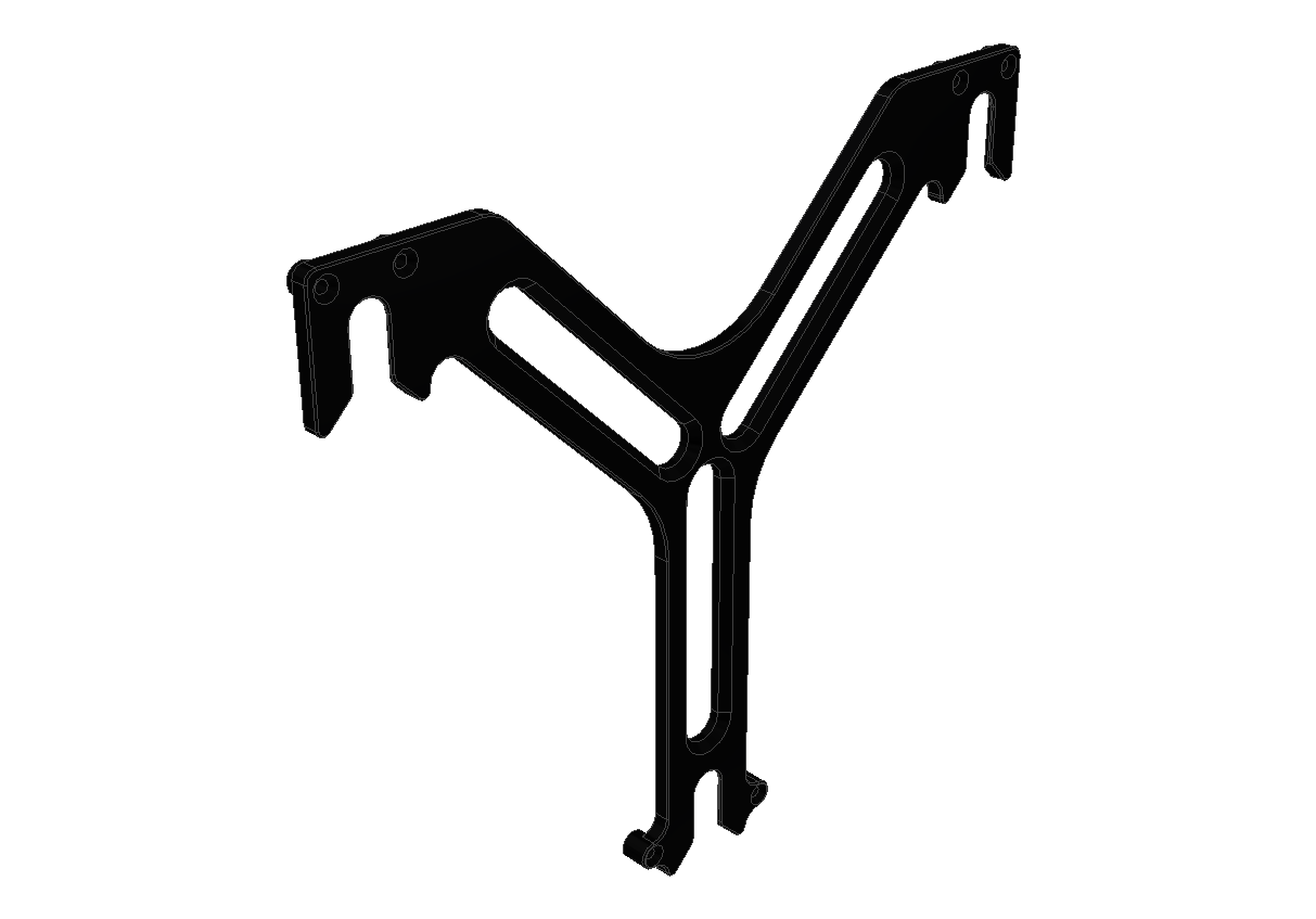
The pole mount is composed by two aluminun brackets to assemble the PCS to the foldable mast.
To assemble the system follow the next steps:
Attach the two brackets to the PCS Control Station with 2mm allen screw driver.
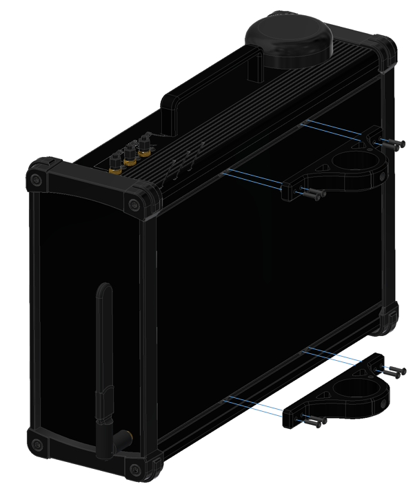
Bracket Fixation
Introduce the PCS Control Station into the mast and attach it with the two wing bolts.
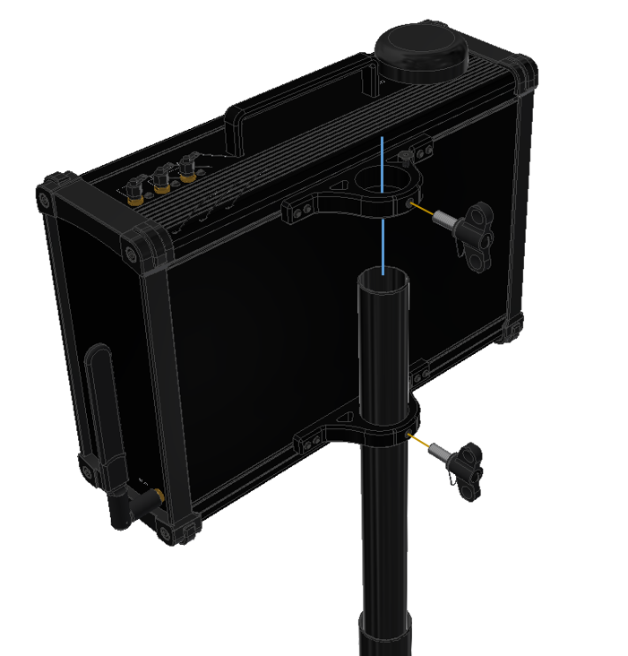
PCS to pole fixation
Attach the antenna to the mast with 13mm open wrench.
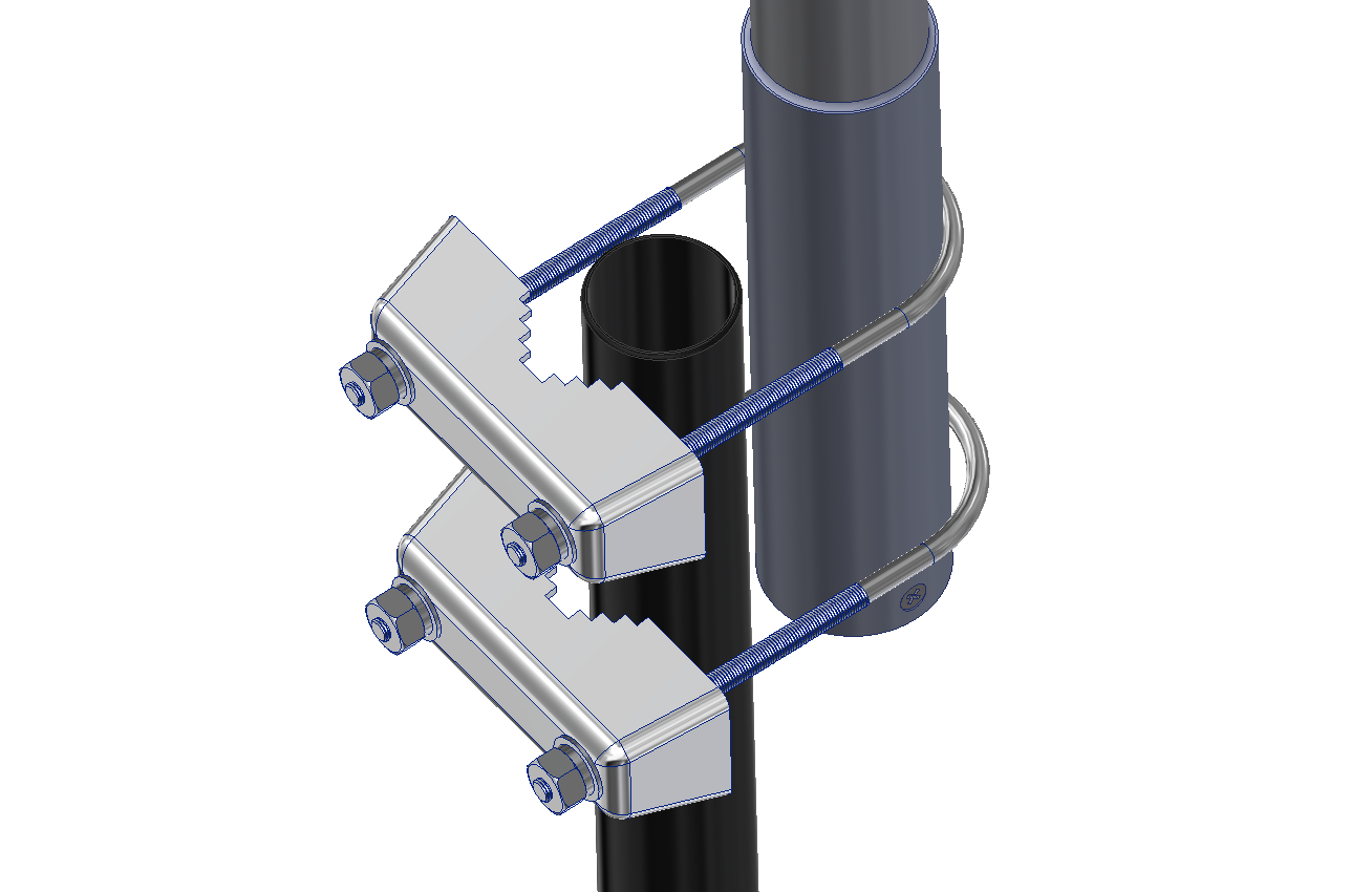
Antenna Fixation
Connect the Antenna to the PCS Control Station (N-Male to SMA cable).