Hardware Installation
Assembly
Two M3 screws are recommended to assemble mechanically the MC01 to a frame. Its fixation holes do not have thread, then it is necessary to use more than 2mm as thread depth.
Pinout/Connections
20 Pin Connector
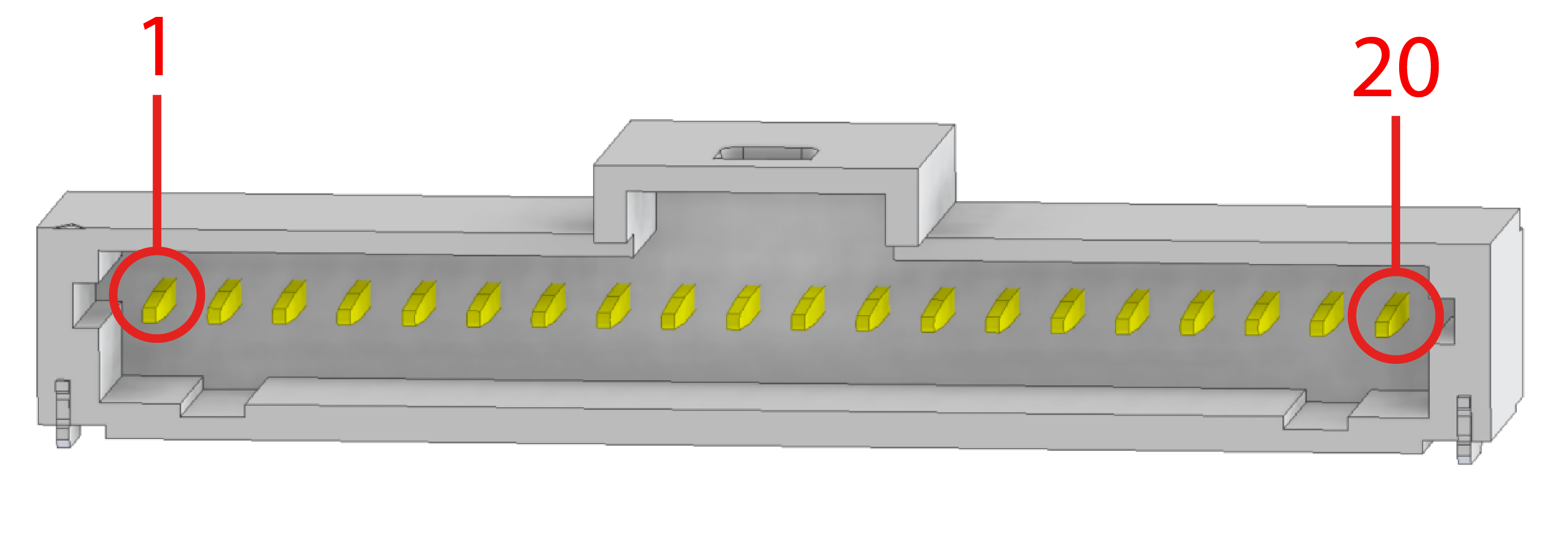
Allocation pin numbers
Number |
Colour |
Inputs |
Use |
|---|---|---|---|
1 |
Brown |
EQEP1L |
EQEP Encoder |
2 |
Red |
EQEP1S |
EQEP Encoder |
3 |
Orange |
EQEP1B |
EQEP Encoder |
4 |
Yellow |
PWM1/ECAP |
PWM/ECAP |
5 |
Green |
EQEP1A |
EQEP Encoder |
6 |
Blue |
3.3V |
Output Power |
7 |
Purple |
PWM2/ECAP |
PWM/ECAP |
8 |
Gray |
CAN (N) |
CAN negative |
9 |
White |
CAN (P) |
CAN positive |
10 |
Black |
GND |
Ground |
11 |
Brown |
SDA |
I2C |
12 |
Red |
SCL |
I2C |
13 |
Orange |
INPUT POWER |
Voltage supply |
14 |
Yellow |
5V |
Output Power |
15 |
Green |
MISO+ |
SPI Encoder |
16 |
Blue |
MISO- |
SPI Encoder |
17 |
Purple |
CLK- |
SPI Encoder |
18 |
Gray |
CLK+ |
SPI Encoder |
The encoder information is received as a differential signal between MISO+ and MISO-, with a differential clock signal between CLK+ and CLK-.
3 Pin Output Connector
The 3 pin connector has the power outputs for motor power supply, each pin corresponds to a phase (A, B and C).
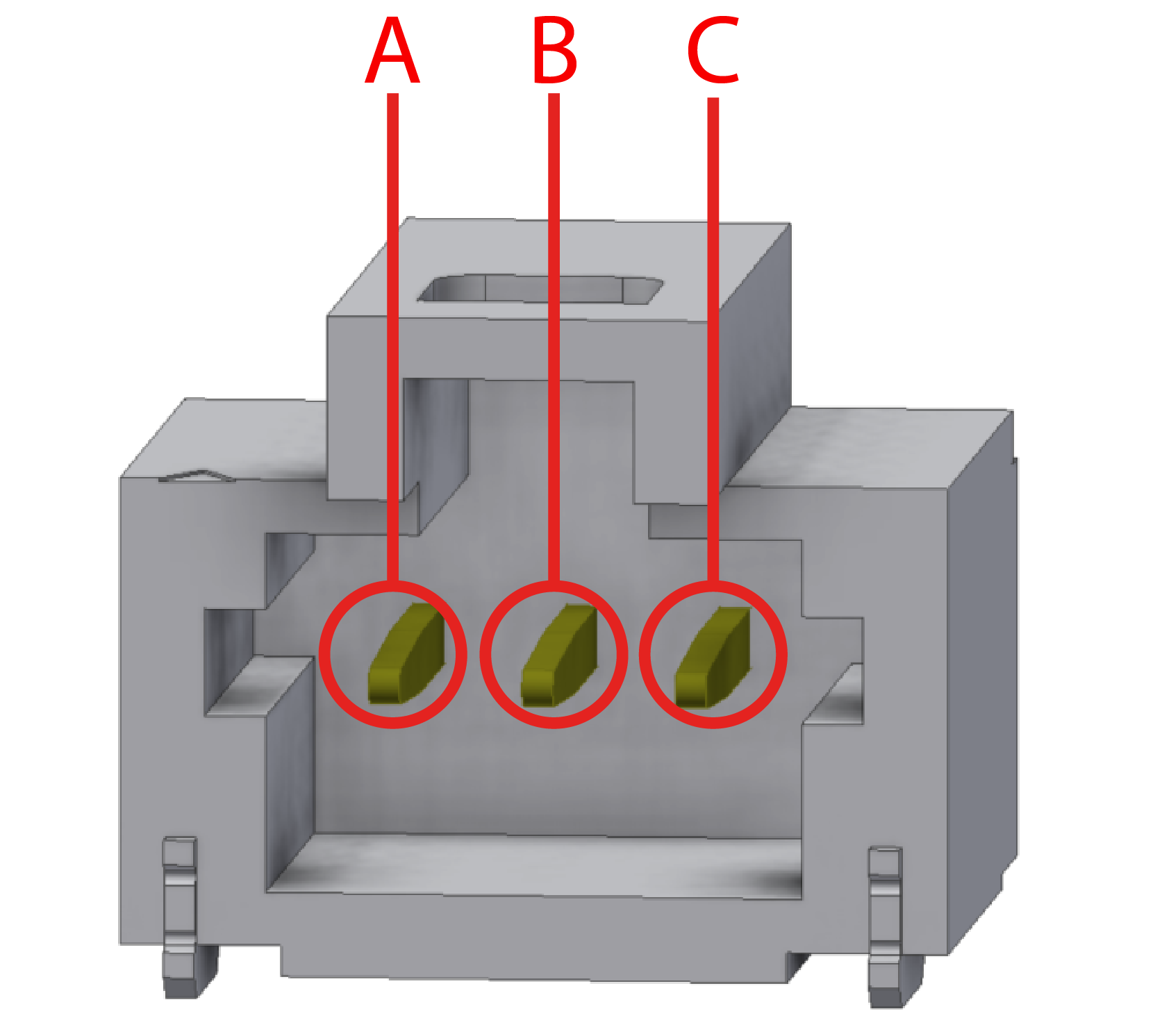
Allocation pin phases
CAN Assembly
A 120 Ohm resistor is required to connect via CAN a MC01 With a Veronte Autopilot. The following figure describes how to assembe the CAN connection with more devices.
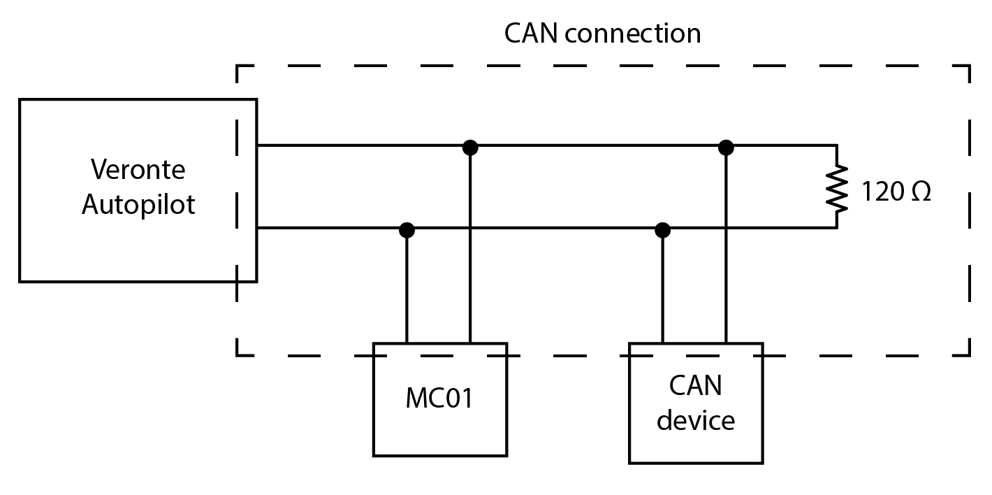
CAN circuit