Software Installation
To configure Veronte SDL, first of all, it must be connected to a computer. This connection can be established in two ways: directly to a computer or through a tunnel with Veronte Autopilot 1x.
Tunnel connection is recommended for basic configuration if a 1x is available, since the interface is more friendly user. Nonetheless, to change advanced parameters the user will have to send AT commands (as messages with the same interface).
Note
Veronte SDL configuration is identical whether used alone or together with an amplifier.
Direct Connection
The following diagram summarizes how to connect a computer to SDL / SDL + Amplifier, so it can be configured.
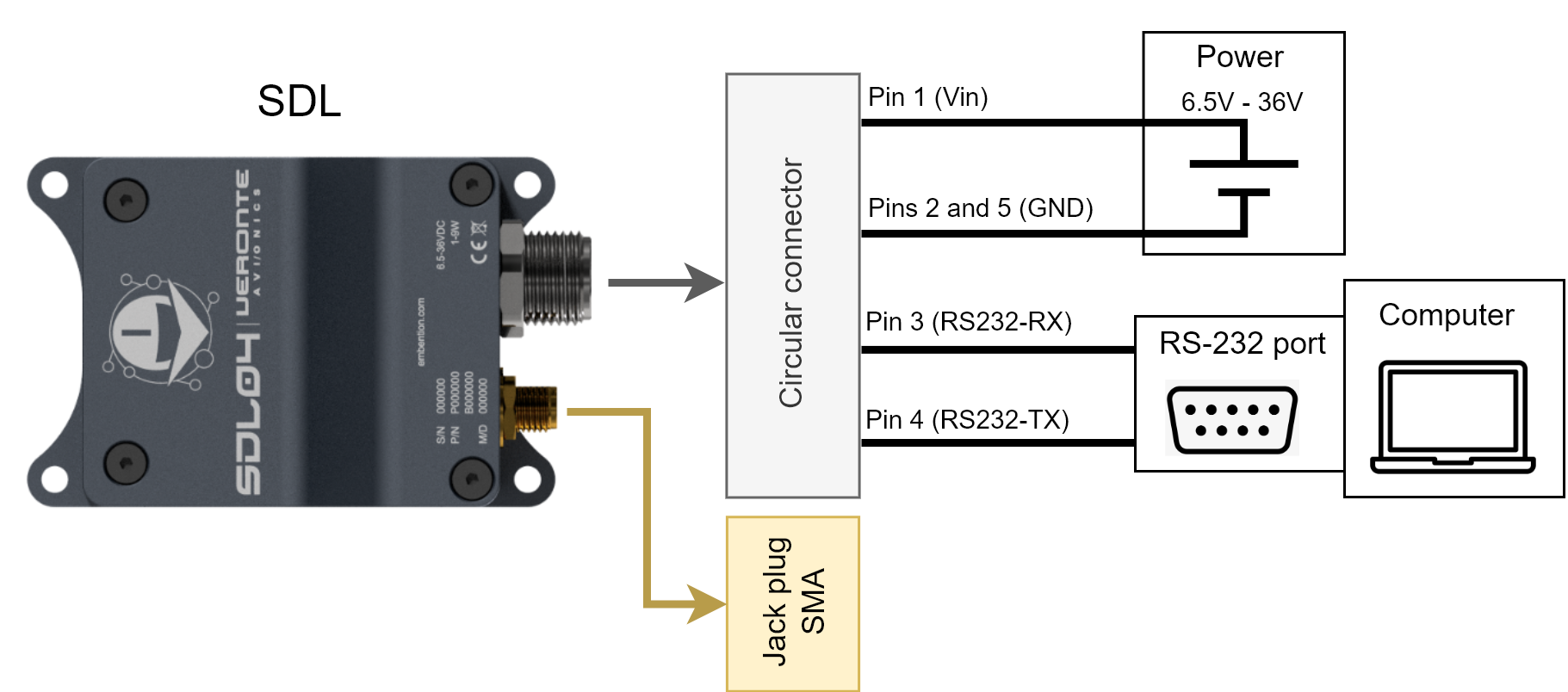
Direct connection to computer
In case of not having a RS-232 port, a RS-232 to USB converter can be used.
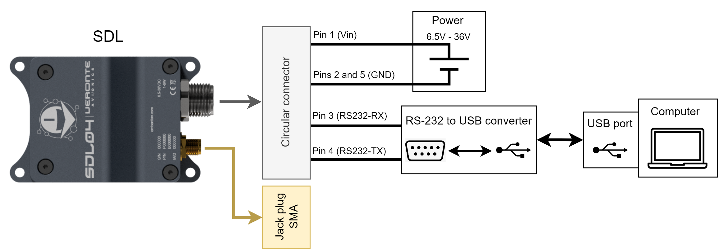
Direct connection to computer with USB converter
Tunnel Connection
The following diagram shows a way of connecting an SDL / SDL + Amplifier to a computer through a 1x tunnel.
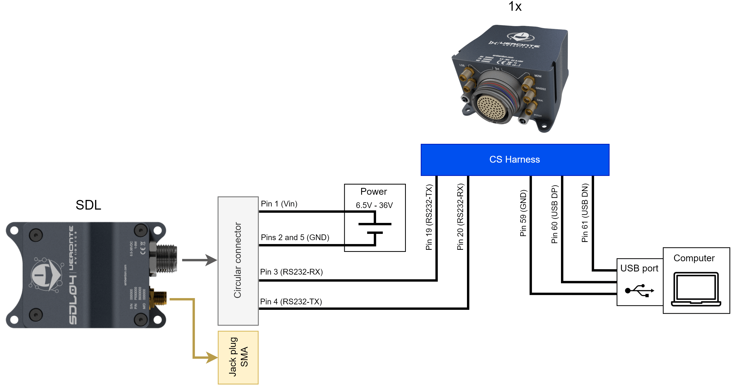
Tunnel connection to computer
How to configure SDL
Once the electrical connection has been made (in the previous sections), SDL can be configured. The configuration method changes according to the connection type (direct or tunnel). Read the subsection which corresponds to the built connection.
Note
Veronte SDL configuration is identical whether used alone or together with an amplifier.
Configuration for Tunnel Connection
First of all, initialize the communication between computer and 1x using Veronte Link, to know more, read its user manual. Then, configure the 1x to establish tunnel communication through RS-232. This configuration is explained in the Terminal - Operation section of 1x PDI Calibration user manual.
Configuration using wizard
Since a wizard is included in the 1x PDI Calibration software to aid in the configuration of the Microhard radio, users can use it as this wizard also works with SDL. Therefore, the Microhard Setup Helper - Terminal subsection should be read when configuring SDL.
Finally, the interface should be similar to the following window:
Terminal manager configured for SDL
Configuration sending AT commands directly
It is also possible to configure the SDL directly with AT registers and AT commands sent with the terminal through this tunnel.
To send these messages correctly, users must:
Change the End Of Line parameter to None.
Type “+++” message and press Send. The radio will respond with “NO CARRIER OK”.
Change the End Of Line parameter back to EOL to send the desired commands.
To know more about the messages, read the SDL configuration subsection of the variant used:
Configuration for Direct Connection
Users can configure the radio as explained above, by sending AT commands but connecting directly to it without using an Autopilot 1x acting as a tunnel.
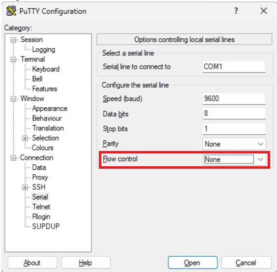
For this, a communication terminal (such as Kitty or Putty) is required to send these commands to the device.
Important
If Putty communication terminal is used, ensure that the Flow Control is configured as None.
Flow Control Configuration
SDL is delivered with the following default configuration:
Register |
Default value |
Description |
|---|---|---|
S101 |
2 |
Operating mode: 2 sets the slave mode, usually employed for air units. |
S104 |
1234567890 |
Network address. |
S107 |
7 |
Serial baud rate: 7 establishes 9600 bps. |
To know more about registers, read the AT Registers subsection of each SDL variant:
To configure the module, follow the steps below:
Once SDL is connected to a computer, open a communication terminal.
Set 9600 bps as baudrate, serial as communication type and the COM port where SDL is connected.
To know which port the computer, open the Device Manager from Windows.
Open the communication.
Write “+++” and wait 1 second to establish the communication. The radio will respond with “NO CARRIER OK”.
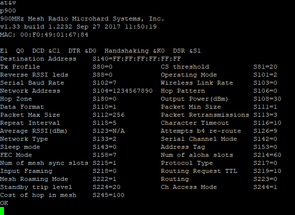
Type “at” and press
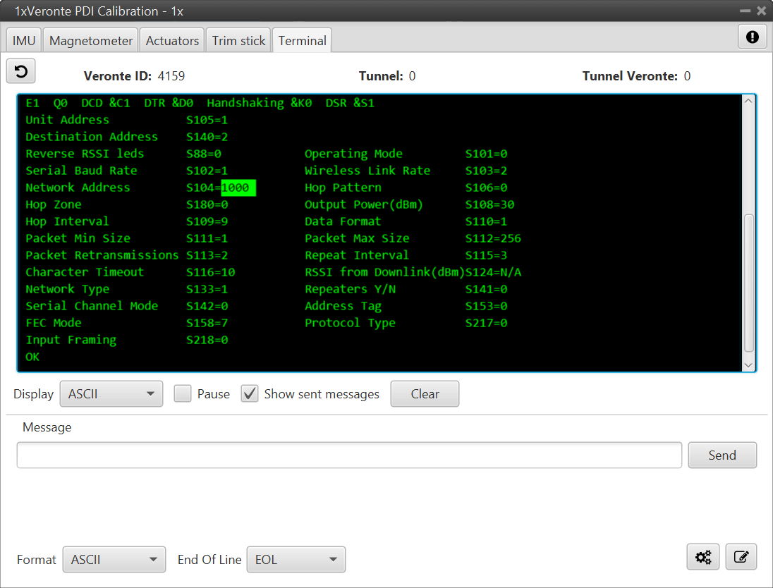
enterto check that communication has been established. The terminal should respond with “ok”.(optional step) To know more about the device configuration, type “at&v”, then a message like the following one will be displayed.
Send the AT commands by typing in the terminal to configure the SDL. These commands are different depending on the desired configuration.
Remember that the parameter “S104” (destination address) must be the same for all radios communicating on the same network.
Tip
If the connection is lost due to a change in baudrate, restart the communication terminal and use the new baudrate.
Configuration for each variant
To configure each SDL variant, read the SDL configuration subsection for each one: