Hardware Installation
Assembly
M3 screws are recommended for mounting. In saline environments such as coastal and oceanic, the screw material must be stainless steel.
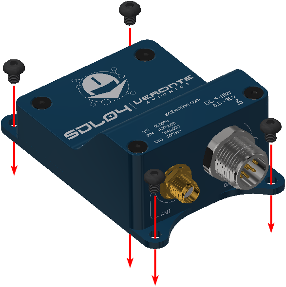
SDL assembly
Antenna Integration
The system uses different kinds of antennas to operate that must be installed on the airframe. Here you can find some advice for obtaining the best performance and for avoiding antenna interferences.
Maximize separation between antennas as much as possible.
Keep them far away from alternators or other interference generators.
Always isolate antenna ground panel from the aircraft structure.
Make sure the antenna is securely mounted.
Always use high-quality RF wires minimising the wire length.
Always follow the antenna manufacturer manual.
SMA connections shall be tightened applying 1Nm of torque.
For all-weather aircrafts, insert SMA lightning protectors.
Take into account
The recommended protection against lightnings is to install a surge arrestor at the antenna and another one at the interface. Surge arrestors should be fully interconnected with all the electrical system to have a commond ground.
SDL may only operate using an antenna which type and power are approved by the transmitter. To prevent radio interferences to other users, the antenna type must be chosen and sized to not beam more than the necessary EIRP.
The number of antennas employed on a single network has an effect on the performance of the link rate, since it is shared by all nodes.
The physical distance between antennas (transmitter and receiver) dictates their performance and required lengths. To choose the antenna type, consider the directivity (omnidirectional or directional) of the antennas being used.
Terrain is also an important consideration for antenna height sizing, since antennas should have a LOS, (they need to “see” each other). Nonetheless, LOS is not enough to completely satisfy RF path requirements for a robust communications link. LOS requires a clear path denominated “Fresnel Zone”.
The fade margin is the difference between the supposed receive signal level and the minimum required. Usually, a desired fade margin is approximately 20 dB, but 10 dB may work properly.
Radio frequencies are not affected by rain. Frequency ranges penetrate through foliage and around small obstacles. Then, some may scrimp on physical equipments, specially antenna heights.
FHSS is a method to transmit radio signals by rapidly changing the frequency to different frequencies, occupying a large spectral band. It allows to work well in an environment with sources of interferences at certain bands.
Antenna types
An omni directional antenna spreads its energy in all directions (hence the name ‘omnidirectional’), with a donut as energy field shape and vertical polarization.
A yagi antenna has a focused energy shape with a greater gain, since it has the shape of a raindrop moving along the antenna direction. If the poles of the yagi are perpendicular to the ground, the signal will be vertically polarized; if they are parallel, the signal will be horizontally polarized.
Operating antennas
This device has been designed to operate with the antennas listed below with a gain lower than 13.2 dBi. Different antennas are strictly prohibited. The required antenna impedance should be 50 ohms to prevent potential interferences to other users, the antenna type and its gain should be chosen that the EIRP is not more than required for communication.
Operating antennas list for SDL04 and SDL09
Type |
Commercial reference |
Description |
|---|---|---|
Rubber Ducky |
MHS031000 |
2dBi, 900MHz Rubber Ducky Antenna RPTNC Swivel |
MHS031070 |
2dBi, 900MHz Rubber Ducky Antenna Reverse SMA Swivel |
|
MHS031080 |
2dBi, 900MHz Rubber Ducky Antenna Reverse SMA Straight |
|
Transit antennas |
MHS031210 |
3dBd, 900 MHz Transit Antenna with Ground Plane |
MHS031220 |
3dBd, 900MHz Transit Antenna No Ground Plane |
|
MHS031230 |
3dBd, 900MHz Transit Antenna Permanent Mount GP |
|
MHS031240 |
3dBd, 900MHz Transit Antenna Permanent Mount NGP |
|
Yagi Antennas |
MHS031311 |
6dBd, 900MHz Yagi Directional Antenna Antenex, RPTNC Pigtail |
MHS031431 |
6.5dBd, 900MHz Yagi Directional Antenna Bluewave, RPTNC Pigtail |
|
MHS031501 |
9dBd, 900MHz Yagi Directional Antenna Antenex, RPTNC Pigtail |
|
MHS031441 |
10dBd, 900 MHz Yagi Directional Antenna Bluewave, RPTNC Pigtail |
|
MHS031451 |
11dBd, 900 MHz Yagi Directional Antenna Bluewave, RPTNC Pigtail |
|
Patch Antennas |
MHS031440 |
8dBi, 900 MHz, Patch Antenna, RPTNC Pigtail |
Omni Directional |
MHS031251 |
3dBd, 900MHz Omni Directional Antenna Antenex, RPTNC Pigtail |
MHS031461 |
3dBd, 900 MHz Omni Directional Antenna Bluewave, RPTNC Pigtail |
|
MHS031321 |
6dBd, 900MHz Omni Directional Antenna Antenex, RPTNC Pigtail |
|
MHS031471 |
6dBd, 900 MHz Omni Directional Antenna Bluewave, RPTNC Pigtail |
Note
Mounts for Transit Antennas have a RPTNC Pigtail.
Operating antennas list for SDL24
Type |
Commercial reference |
Description |
|---|---|---|
Rubber Ducky |
MHS031100 |
2 dBi,2.4 GHz Rubber Ducky Antenna RPTNC Swivel |
MHS031110 |
2 dBi, 2.4 GHz Rubber Ducky Antenna Reverse SMA Swivel |
|
2.5 dBi, Shenzhen Norminson Technology CO.LTD. - 2.4 GHz Rubber Ducky Antenna |
||
NW001 |
Reverse SMA Straight |
|
WCP2400-MMCX4 |
2.5 dBi, Laird Technologies - 2.4 GHz Rubber Ducky MMCX |
|
Yagi antennas |
MHS034100 |
9 dBi, 2.4 GHz Yagi Directional Antenna RPTNC Pigtail |
MHS034000 |
12 dBi, 2.4 GHz Yagi Directional Antenna RPTNC Pigtail |
|
MHS034120 |
14 dBi, 2.4 GHz Yagi Directional Antenna RPTNC Pigtail |
|
MHS034150 |
14.5 dBi, 2.4 GHz Yagi Directional Antenna RPTNC Pigtail |
|
Patch antennas |
MHS034200 |
8 dBi, 2.4 GHz Mini Flat Patch Directional Antenna RPTNC Pigtail |
MHS034210 |
14 dBi, 2.4 GHz Flat Patch Directional Antenna RPTNC Pigtail |
|
Omni Directional |
MHS031260 |
5 dBi, Omni Directional Antenna RPTNC Pigtail |
MHS034000 |
6 dBi, 2.4 GHz Omni Directional Antenna RPTNC Pigtail |
|
MHS031340 |
8 dBi, Omni Directional Antenna RPTNC Pigtail |
|
MHS034020 |
10.5 dBi, 2.4 GHz Omni Directional Antenna RPTNC Pigtail |
|
MHS034030 |
12 dBi, 2.4 GHz Omni Directional Antenna RPTNC Pigtail |
|
MHS034040 |
15 dBi, 2.4 GHz Omni Directional Antenna RPTNC Pigtail |
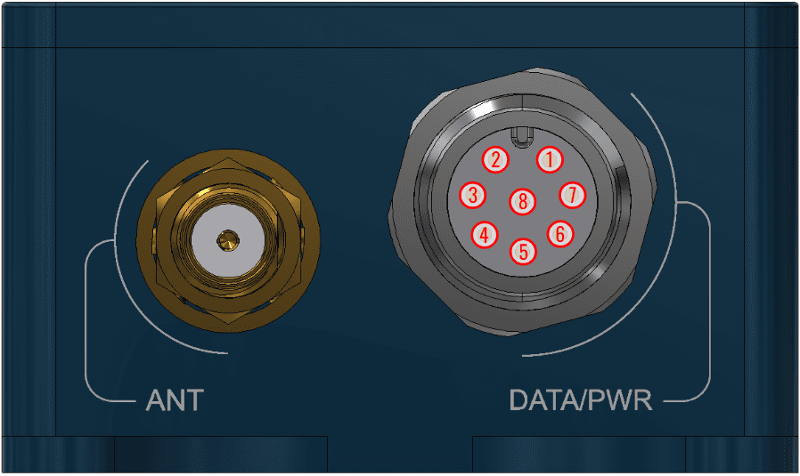
Pinout
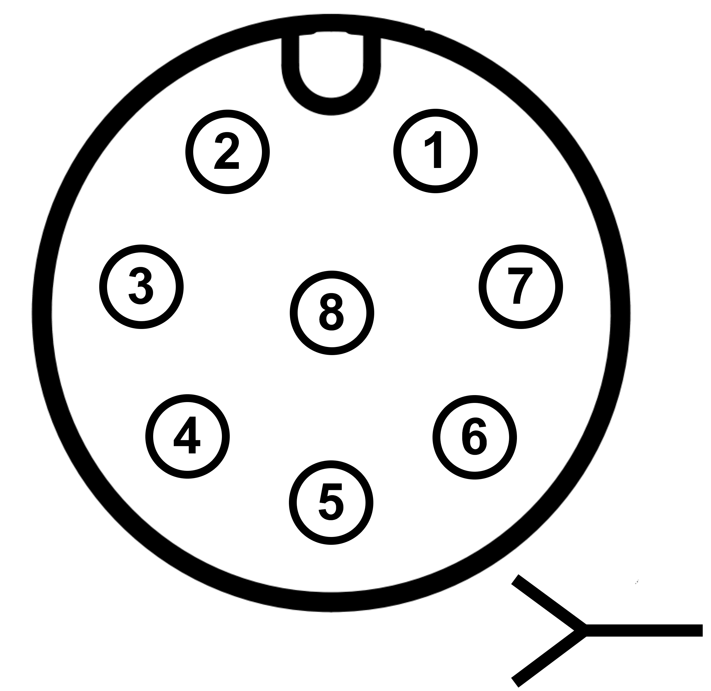
Connector pinout
Clarification
Corresponds to the connector on the radio module side (commercial reference T4144015081-000):
PIN |
Signal |
Type |
Description |
|---|---|---|---|
1 |
Vin |
Power |
Voltage supply 6.5-36V |
2 |
GND |
Power |
Ground for logic, radio, and I/O pins |
3 |
RS232-RX |
Input |
Receive Data |
4 |
RS232-TX |
Output |
Transmit Data |
5 |
GND |
Power |
Ground for logic, radio, and I/O pins |
6 |
RSSI1 |
Output |
Received Signal Strength Indicator 1. 0 V for low / 3.3 V for high |
7 |
RSSI2 |
Output |
Received Signal Strength Indicator 2. 0 V for low / 3.3 V for high |
8 |
RSSI3 |
Output |
Received Signal Strength Indicator 3. 0 V for low / 3.3 V for high |
RSSI pins are digital output signals that indicate RF connection quality.
Signal strength according to RSSI pins |
|||
|---|---|---|---|
Pin 6 - RSSI1 |
Pin 7 - RSSI2 |
Pin 6 - RSSI3 |
Signal strength |
HIGH |
HIGH |
HIGH |
Strong |
HIGH |
HIGH |
LOW |
Medium |
HIGH |
LOW |
LOW |
Weak |
LOW |
LOW |
LOW |
Lost |
Connections
After configuring SDL it has to be connected to the rest of the devices according to the following diagram, where each pin is refered in the Pinout section of this manual.
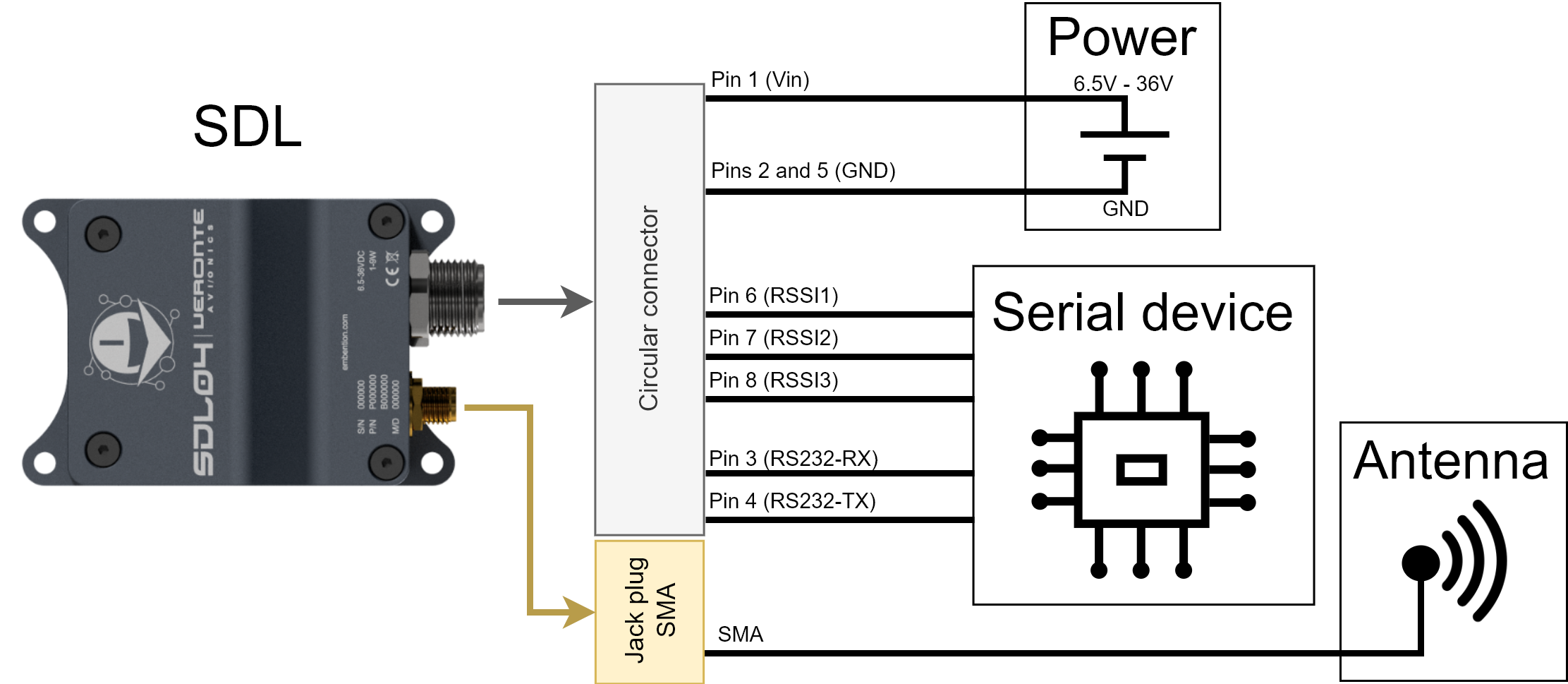
Hardware Installation wiring diagram
Autopilot 1x can be used as serial device employed. To know how to do it, read Veronte SDL - Integration examples section of the 1x Hardware Manual.