Landing
Landing guidance is used to create the route that the airplane will follow to land in a certain runway (defined by the user).
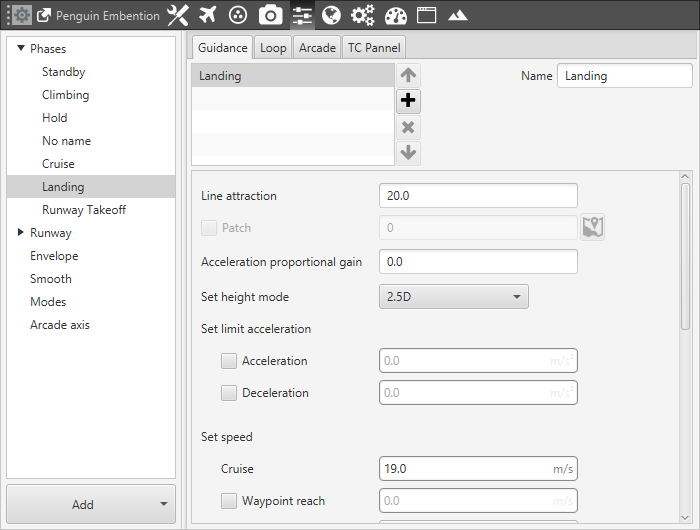
Landing Guidance
Line attraction: as in the case of the climbing, is a parameter that determines how the aircraft is attracted to the line that it has to follow. The value is the distance perpendicular to the path at which the vehicle will try to go back to the line with a heading of 45 degrees with respect to it. When it is closer than this distance the heading angle is lower, and bigger when the distance is higher. So a small value will make the aircraft go to the line at high angles during more time (because the distance of 45 degrees is now small), and a big value implies less attraction because the platform will go to the line at smaller angles than 45 degrees from a bigger distance.
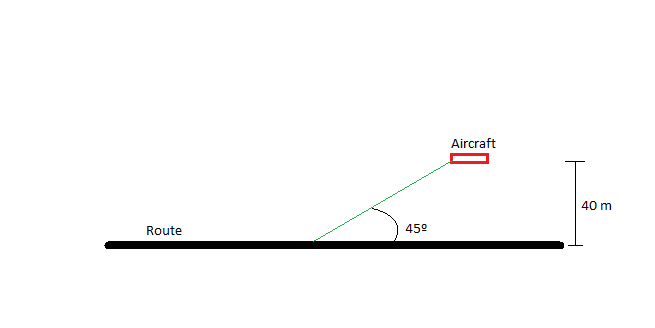
Angle and distance
In the this phase the path is not directly indicated by the user as in the cruise (which is defined in the Mission menu) but there is still a trajectory whose parameters are detalied later in this section, so this value is as important as it is for the Waypoint following route. The common values of the line attraction are between 20 and 40 for airplanes, and 15 for multicopters. This parameter only has to be changed by advanced users.
Acceleration proportional gain: this parameters is releated with a new control system that Embention is developing in which elevator and thurst work side by side in both the pitching and thrusting.
Set height mode: the height mode indicates how the aircraft will perform the route.
2D mode: if this mode it is selected, the platform will follow the predifined route without taking into account the altitude of the waypoints, it will keep the altitude that it has at the moment it enters in the cruise guidance.
2.5D mode: is used in multicopters only, in this case the vehicle will climb vertically to the altitude of the first point of the route and then it will begin it.
3D mode: the vehicle goes from the altitude at which it enters in cruise mode, to the beginning of the route in a diagonal trajectory (it follows a 3D trajectory that connects the two points).
Set speed: this option sets the speed that the vehicle will have during the climb. It can be IAS (indicated airspeed) or Speed (Ground Speed). Normally, IAS is used for airplanes and Speed for multicopters. The option Waypoint reach is used to indicate the speed at which the platform will reach the waypoints, so it will travel along the path with the speed indicated in the option Cruise, then it will decelerate or accelerate to the speed indicated in Waypoint Reach and then it will go back to the cruise speed.
Route: the route section of the landing guidance defines the route that the aircraft takes to go from the point when this phase is commanded, to the point where it touches the ground. The landing route has two parts: the first one consists on a descending loiter used to descend from the cruise altitude to an altitude where the manoeuvre of heading the airplane towards the runway direction and make it touch ground can be performed, the second part is the path that takes the aircraft to ground (to the runway). If the airplane starts the landing phase at an altitude at which it can perform the landing manoeuvre without the descending loiter, this one will not be performed, so the descending circular route will automatically be done when the aircraft is at a great height. The parameters that define the landing route are presented as follows:
Loi Force: force aircraft to perform loiter manoeuvre.
Runway: select a runway o spot previously defined, see section ref 6.7.2 . Besides, it is possible to use the advanced mode and select a different loiter/touch point and direction.
Loiter Pos: center point of the loiter descending route.
Flight Path Angle: angle at which the aircraft will descend.
Horizontal Distance: is the distance from the point where the aircraft is alligend with the runway to the start of the it.
Radius Head Turn R3: radius of the turn made to head the airplane towards the runway direction.
Radius loiter R1: radius of the loiter descending made by the aircraft to reach an altitude suitable to perform the landing manoeuvre.
The following figure details schematically all the parameters detailed previously.
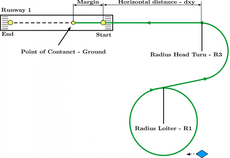
Landing Route