Arbiter CAN protocol
This section describes the CAN Bus protocol actually in use for the communication between the Arbiter and the Autopilots in Redundant Veronte Autopilot. Veronte is able to use both Standard CAN and Extended CAN messages. In this first integration step, the messages are configured following the Standard CAN communication protocol.
CAN parameters
The following Standard CAN parameters are described according to the Veronte Pipe configuration:
Baudrate: 1 [Mbps].
TX Ini: in this section is set the Start Message. Period has a value of 1 [s].
TX: this section has to be configured as it is shown below. Period has to be set to 0.1 [s]
RX: None.
CAN message structure
The message that each Autopilot (Veronte or External) connected to the Arbiter must send through CAN Bus has to be as follows:
Name |
Variable 1 |
Variable 2 |
Variable 3 |
Start Message (TX Ini) |
|---|---|---|---|---|
Endianness |
Little Endian |
Little Endian |
Little Endian |
Little Endian |
ID |
Autopilot ID |
Autopilot ID |
Autopilot ID |
Autopilot ID |
Variable X: variable sent to the Arbiter. In this first integration phase, they are Roll, Pitch and Yaw angles.
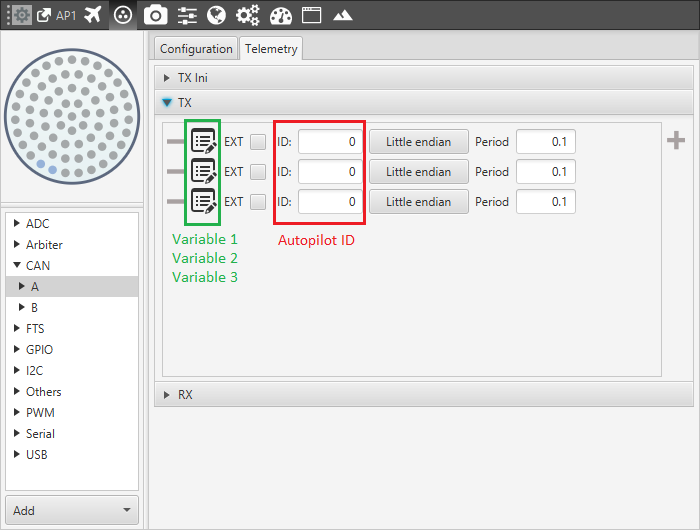
Variable X – Veronte AP 1
Start Message: the arbiter will start to arbitrate only when it reaches the start message from all Autopilots. The start message must be like the following:
Start Message Structure¶ Name:
Matcher 1
Matcher 2
Matcher 3
Bits Number
16 bits
16 bits
1 bit
Value
Autopilot ID
65535
1
Where:
Autopilot ID Number¶ Name:
Veronte AP 1
Veronte AP 2
Veronte AP 3
External AP
Autopilot ID
0
1
2
3
The following image shows this configuration using Veronte Pipe and Veronte AP 1.
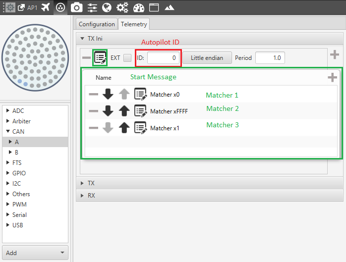
Start Message – Veronte AP 1
Endianness: In this case, all the messages are configured with a Little Endian structure.
ID: The ID of the Autopilot that is sending the message (value from 0 to 3).
Single message structure
The structure of the messages including the single variables sent from the Autopilots must be configured like the following:
Matcher 1 |
Matcher 2 |
Variable |
|---|---|---|
16 bits |
16 Bits |
32 bits |
Where:
Matcher 1: Autopilot Identifier. In this case, the value must be from 0 to 3.
Autopilot ID Number¶ Veronte Autopilot 1
Veronte Autopilot 2
Veronte Autopilot 3
External Autopilot
0
1
2
3
Matcher 2: Value ranging from 0 to 2 meaning the variable ID.
Variable: the variable that the Arbiter will receive and monitor. In this first integration step the variables are:
Variable ID¶ Variable
Description
Range [rad]
Variable ID
Bits
Type
Roll
Roll Angle measured from Veronte Autopilot in real time in Body Axes.
(-π, π)
0
32
Float
Pitch
Pitch Angle measured from Veronte Autopilot in real time in Body Axes.
(-π, π)
1
32
Float
Yaw
Yaw Angle measured from Veronte Autopilot in real time in Body Axes.
(0, 2π)
2
32
Float
The following figure shows the configuration for Variable 1 – Roll, using Veronte AP 1.
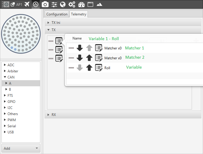
Variable 1 – Roll
The variables can be modified in the Autopilot CAN configuration using Veronte Pipe. To do this it is sufficient to change the variables in the single message in both the Autopilot configurations.
External autopilot simulation
When the External Autopilot is not connected to the Redundant network, it is possible to simulate its presence allowing the Arbiter to start the arbitration. To do this, it is sufficient to add a message sent from one of the active autopilots through the CAN Bus that contains the Start message of the External Autopilot (ID: 3). The following example represents this kind of message sent from Veronte Autopilot 1 (ID: 0):
Message
Autopilot
ID
Variable ID
Type
Value
Description
1
0
0
Variable
Roll Angle
Roll Angle
variable of Veronte Autopilot 1
2
0
1
Variable
Pitch Angle
Pitch Angle
variable of Veronte Autopilot 1
3
0
2
Variable
Yaw Angle
Yaw Angle
variable of Veronte Autopilot 1
4
– TX Ini
0
65535
Start Message
1
Start message of Veronte Autopilot 1
5
– TX Ini
3
65535
Start Message
1
Start message of External Autopilot
External Autopilot Structure
Once the Arbiter starts to arbitrate, the External Autopilot will be automatically discarded and the process will be carried out using the Veronte Autopilots only.
Can protocol for 4-autopilot configuration
When the system in configured integrating four Autopilots (including then: three Veronte Autopilots, one Arbiter and one External Autopilot) the CAN Protocol structure does not change. In this case, the arbiter will expect to receive the Start Message from 4 Autopilots with different ID value that will go from 0 to 3.
The user must take into account that:
the ID order is not important (Veronte 1 can be configured using ID:2 and vice-versa).
the Arbiter does not need any information about the Autopilot type (External or Veronte).
when the number of the Autopilots changes, the Arbiter software has to be modified.
when the number of the monitored variables changes, the Arbiter software has to be modified
The following tables represent a possible configuration of the messages sent from four Autopilots using three monitored variables.
Veronte Autopilot 1:
Message
Autopilot
ID
Variable ID
Type
Value
Description
1
0
0
Variable
Roll Angle
Roll Angle
variable of Veronte Autopilot 1
2
0
1
Variable
Pitch Angle
Pitch Angle
variable of Veronte Autopilot 1
3
0
2
Variable
Yaw Angle
Yaw Angle
variable of Veronte Autopilot 1
4
– TX Ini
0
65535
Start Message
1
Start message of Veronte Autopilot 1
Message Structure AP1
Veronte Autopilot 2:
Message
Autopilot
ID
Variable ID
Type
Value
Description
1
1
0
Variable
Roll Angle
Roll Angle
variable of Veronte Autopilot 2
2
1
1
Variable
Pitch Angle
Pitch Angle
variable of Veronte Autopilot 2
3
1
2
Variable
Yaw Angle
Yaw Angle
variable of Veronte Autopilot 2
4
– TX Ini
1
65535
Start Message
1
Start message of Veronte Autopilot 2
Message Structure AP2
Veronte Autopilot 3:
Message
Autopilot
ID
Variable ID
Type
Value
Description
1
2
0
Variable
Roll Angle
Roll Angle
variable of Veronte Autopilot 3
2
2
1
Variable
Pitch Angle
Pitch Angle
variable of Veronte Autopilot 3
3
2
2
Variable
Yaw Angle
Yaw Angle
variable of Veronte Autopilot 3
4
– TX Ini
2
65535
Start Message
1
Start message of Veronte Autopilot 3
Message Structure AP3
External Autopilot:
Message
Autopilot
ID
Variable ID
Type
Value
Description
1
3
0
Variable
Roll Angle
Roll Angle
variable of External Autopilot
2
3
1
Variable
Pitch Angle
Pitch Angle
variable of External Autopilot
3
3
2
Variable
Yaw Angle
Yaw Angle
variable of External Autopilot
4
– TX Ini
3
65535
Start Message
1
Start message of External Autopilot
Message Structure External