Servo Configuration
W210 configuration process can be performed by using a VerontePipe software version connected with the hardware system and the Autopilot as explained in section Aircraft Mounting of the manual.
Servos Output
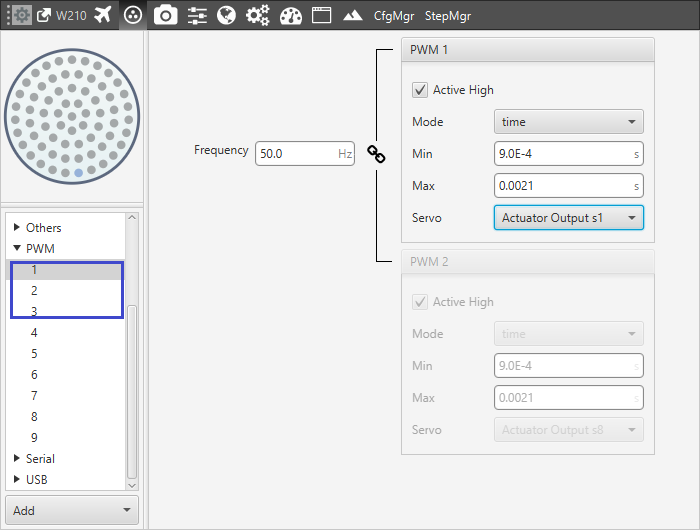
The first step of the process is the servos configuration.
The controls of the airplane are the two control surfaces and throttle. Each one of these control corresponds to a pin of the connector and they must be positioned in the same order in an S vector who represents the Actuator Output. It is possible to connect any pin to any control surface or command but the easiest way to perform it and avoid confusion is by following the pins number.
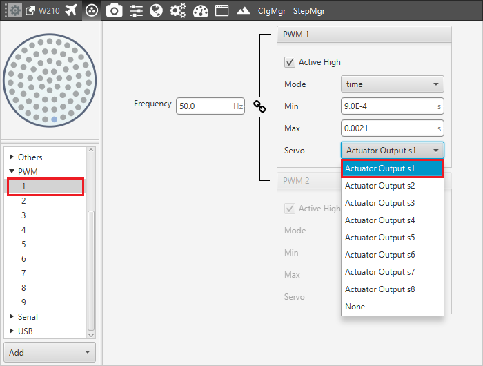
Output-pin links
In this case, it is possible to use only 3 pins:
Output 1 – Actuator Output s1 (Aileron 1)
Output 2 – Actuator Output s2 (Aileron 2)
Output 3 – Actuator Output s3 (Throttle)
Output 1 – pin 1 configuration
SU Matrix
At this point, the S vector is defined and the SU matrix can be edited. By clicking on Edit it is possible to configure the relation between the controller outputs (U vector) and the servo movements (S vector).
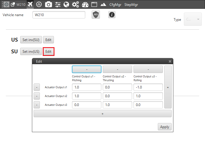
SU matrix editing
The W210 is configured as follow:
Pitch Control: control surfaces must be moved in the same direction to modify the pitching angle. The contribution of the actuators has same magnitude and direction.
Thrust Control: the Actuator Output 1 is the only one that allows a thrusting change.
Roll Control: in this case, the contribution of the actuators must be set with the same magnitude and reverse direction in order to perform a rotation around the X axis.
Warning
This panel shows the reference system of the aircraft. It must be positioned in the same way of the Autopilot’s one. If it results different, it can be edited by clicking on the corresponding axis in order to reverse its direction.
System Trim
As a final step, the system has to be trimmed. This can be performed by moving servos in three different positions: zero position, minimum and maximum deflection angle (angles are usually limited physically). These positions must be inserted and saved in the software by clicking on Set when the actuator is in the desired position. Otherwise, position can be introduced manually.
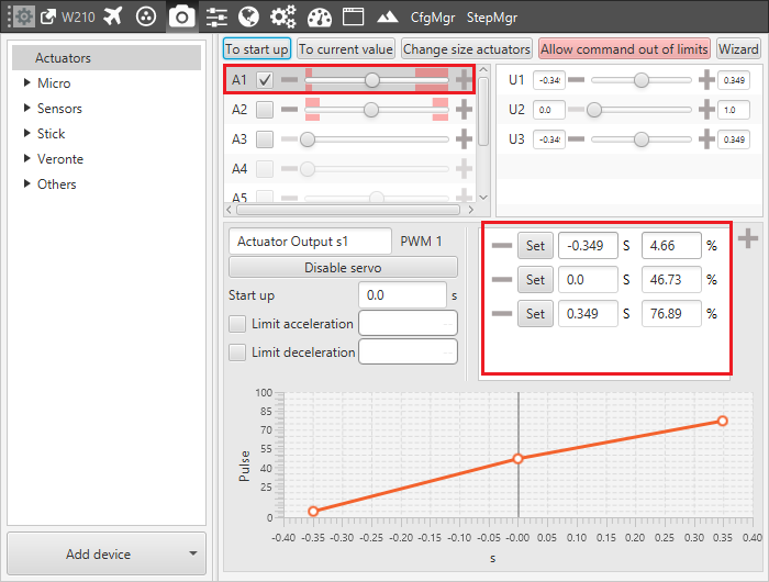
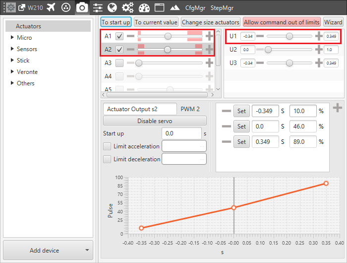
Actuator 1 Trimming
The picture shows the setting of the elevator number 1:
Minimum: -0.34906 [rad] deflection; 4.6682%
Zero position: 0.0[rad] deflection; 46.7317%
Maximum: 0.34906 [rad] deflection; 76.8904%
Warning
The actuators can be moved directly from VerontePipe only when the system is in an Initial phase. During the actuator run, if the desired position is in the Out of range zone (red zone), it is possible to click on Allow command out of limits in order to move completely the actuator and find the correct position.
This procedure can be performed in the same way by using a Wizard. This tool allows moving actuators limits easily and finding the correct range.
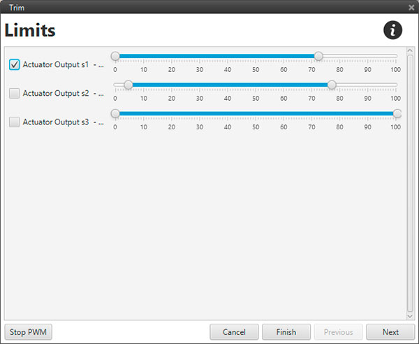
Trim wizard tool
In order to perform a final checking, it is possible to select the desired channel and testing pitch, roll and thrust controls.
The image below shows a pitching output testing. By moving the U1 control, surfaces must change the position according to the reference system: positive corresponds to nose down and negative to nose up.
Pitching test