Hardware Installation
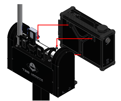
Basic Connection Diagram
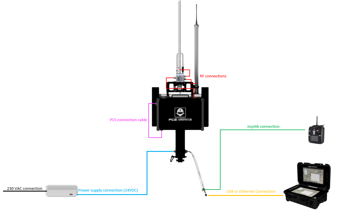
Connection Diagram
Pinout
Tracker Harness connector
The Tracker Harness connector is a 68 pin connector installed on the base of the Pan-Tilt unit. The distribution of input/output channels is as follows:
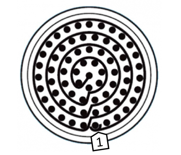
Tracker Harness connector pinout
Pin nº |
Function |
Pin nº |
Function |
Pin nº |
Function |
Pin nº |
Function |
|---|---|---|---|---|---|---|---|
1 |
PWM 1 |
18 |
GND |
35 |
GND |
52 |
Not used (*) |
2 |
PWM 2 |
19 |
RS-232 TX |
36 |
Not used (*) |
53 |
Not used (*) |
3 |
PWM 3 |
20 |
RS-232 RX |
37 |
Not used (*) |
54 |
Not used (*) |
4 |
PWM 4 |
21 |
Ethernet Tx+ (*) |
38 |
ANALOG_1 |
55 |
Not used (*) |
5 |
PWM 5 |
22 |
Not used (*) |
39 |
ANALOG_2 |
56 |
Not used (*) |
6 |
PWM 6 |
23 |
5V |
40 |
ANALOG_3 |
57 |
EQEP_S |
7 |
PWM 7 |
24 |
Ethernet Tx- (*) |
41 |
Ethernet RX- (*) |
58 |
EQEP_I |
8 |
PWM 8 |
25 |
CANA_P |
42 |
Not used (*) |
59 |
GND |
9 |
GND |
26 |
CANA_N |
43 |
Not used (*) |
60 |
USB_DP |
10 |
PWM 9 |
27 |
Not used (*) |
44 |
Not used (*) |
61 |
USB_DN |
11 |
PWM 10 |
28 |
CANB_P |
45 |
Not used (*) |
62 |
Not used (*) |
12 |
PWM 11 |
29 |
CANB_N |
46 |
Not used (*) |
63 |
Not used (*) |
13 |
PWM 12 |
30 |
Ethernet Rx+ (*) |
47 |
GND |
64 |
Not used (*) |
14 |
PWM 13 |
31 |
I2C_SCL |
48 |
Not used (*) |
65 |
GND |
15 |
PWM 14 |
32 |
I2C_SDA |
49 |
GND |
66 |
GND |
16 |
PWM 15 |
33 |
GND |
50 |
Not used (*) |
67 |
Not used (*) |
17 |
Not used (*) |
34 |
Not used (*) |
51 |
Not used (*) |
68 |
Not used (*) |
Note
The functions marked with (*) differ from Veronte PCS Pinout
Warning
RS-485 bus is used by default by the Veronte BCS for Ethernet communications.
Warning
Compatible only with PCS harness. Do not attach other type of harness, please contact us before doing it.
Warning
CANA is used for internal propouses and is already equipped with two CAN termination resistors. No extra termination resistor shall be added to the CANA bus. CANB has no CAN termination resistors, user shall add them based on its own wiring design. We recomend to use CANB for customer inplementation and CANA for internal propouses, although CANA can also be used for customer implementations.
Power connector
The connector installed in veronte tracker pole is the 71-533722-06P. Use PT06A-10-6S(005) as mating connector.
Next table describes the pinout of the power connector:
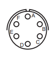
Power connector pinout
Pin |
Function |
|---|---|
A |
24V |
B |
24V |
C |
24V |
D |
GND |
E |
GND |
F |
GND |
PAN-TILT Unit installation
To install the PAN-TILT Unit on the Mast next steps shall be followed.
Insert PAN-TILT Unit into the Mast and insert the two M10 screws.

Insert PAN-TILT Unit into the Mast
Fix the two M10 screws with an 8mm Allen wrench.
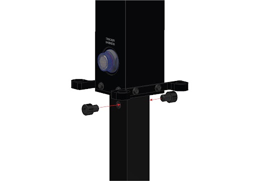
Fix tracker in to the mast
PCS installation
Veronte PCS needs to have the Wall Mount accessory installed.
Wall mount accessory
In the next picture are marked the hanging points where Veronte PCS shall be installed.
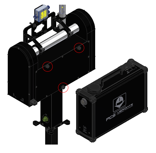
Hanging points
Slide the Veronte PCS into the three hanging points.
Slide Veronte PCS
Antennas installation
This chapter describes how to install each type of antenna
Omnidirectional Antenna
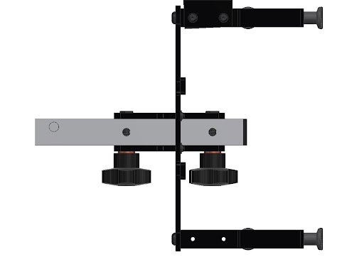
Insert the Omnidirectional Antenna through the holes prepared for that purpose.
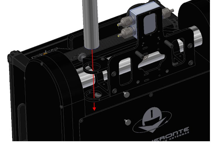
Fix the Parabolic Omnidirectional Antenna with the two lobe knobs.
The next image illustrates the final configuration.
Parabolic Grid Antenna
Fit the 4 grids with the protrusions.
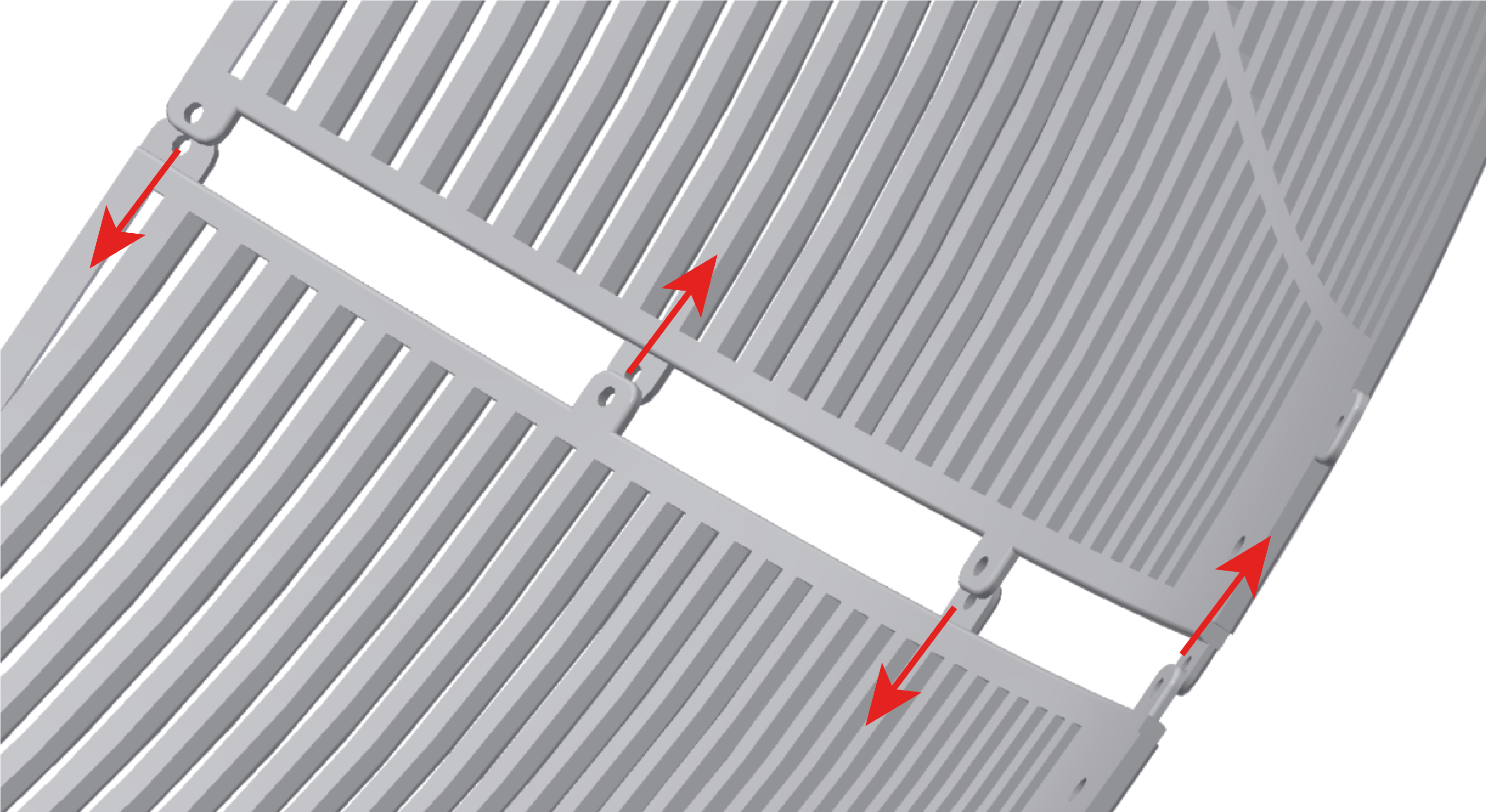
They must be fitted like the next figure:

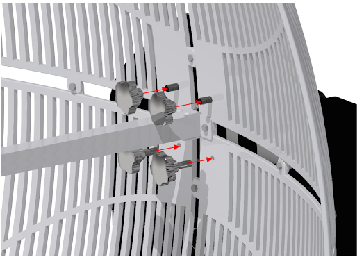
Screw the 4 pieces with twelve screws M5x15 and their corresponding nuts.
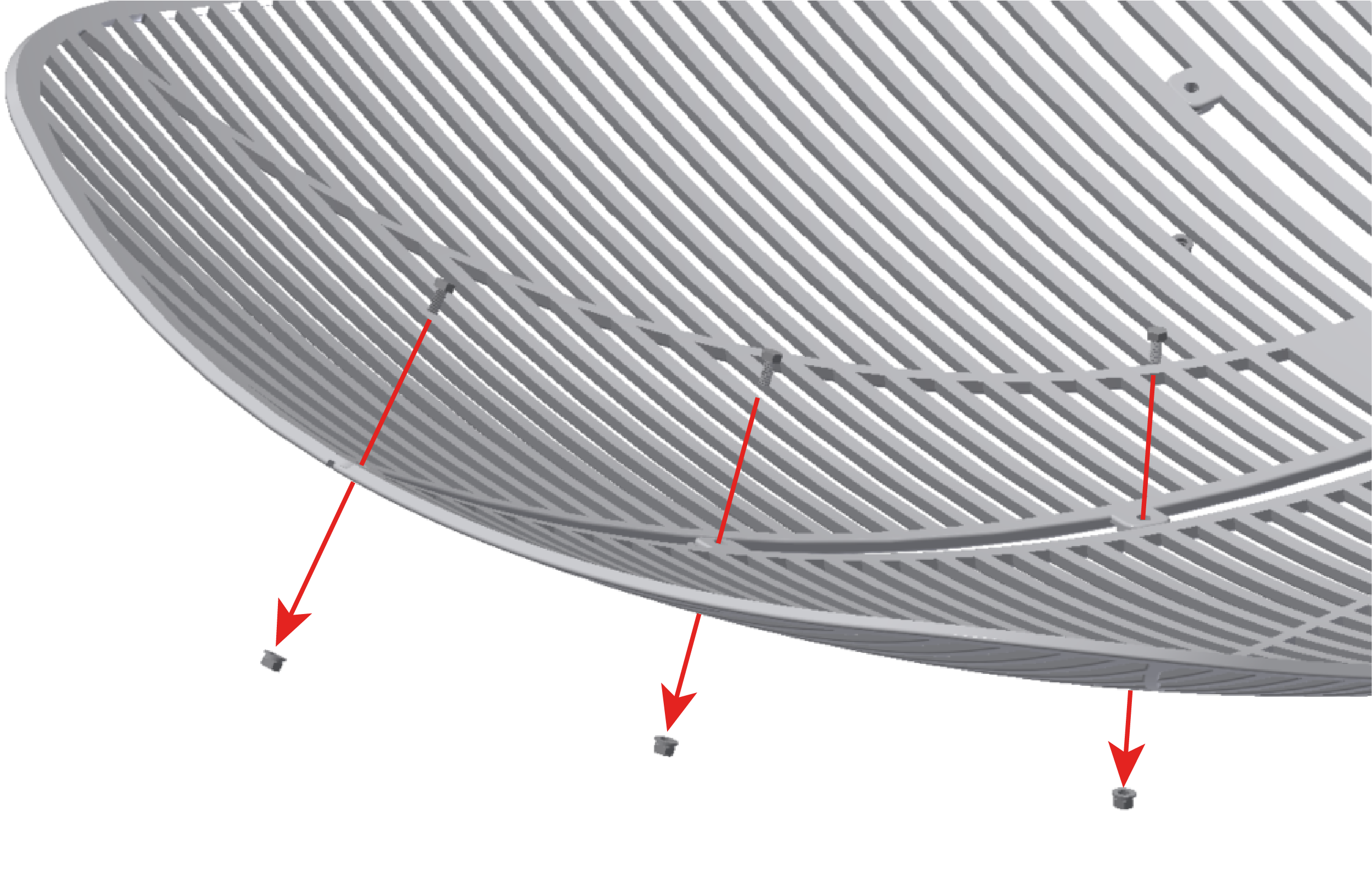
Screwing one of four sides
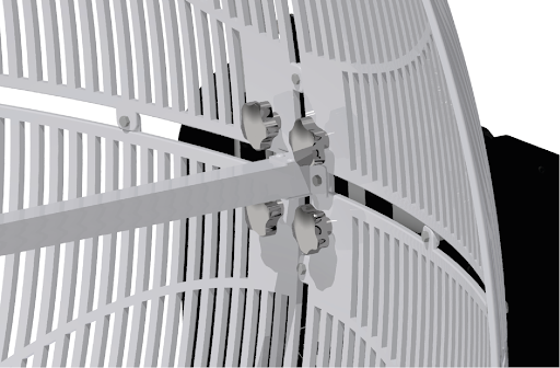
Screw the horn to the grids with two screws M5x15 and their corresponding nuts.
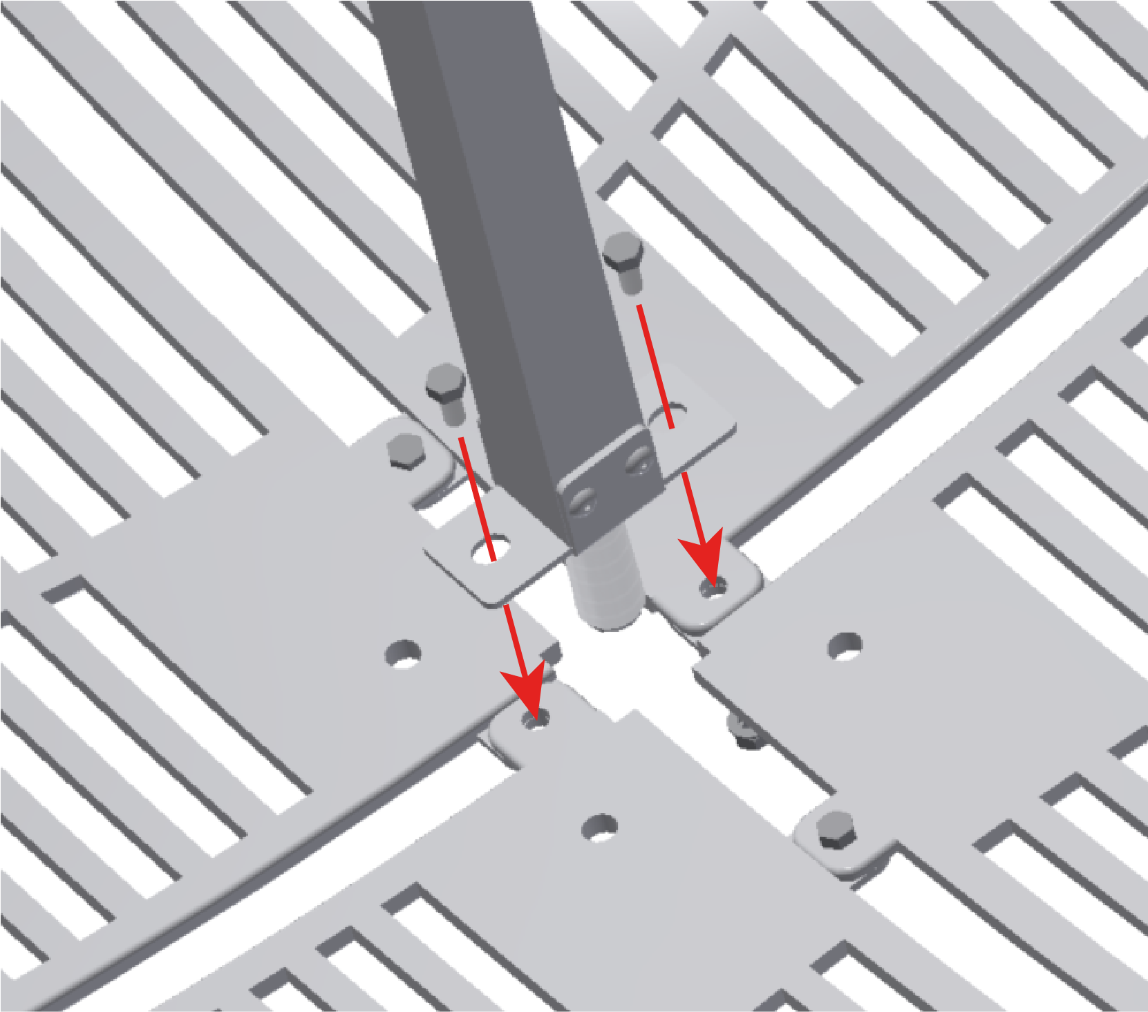
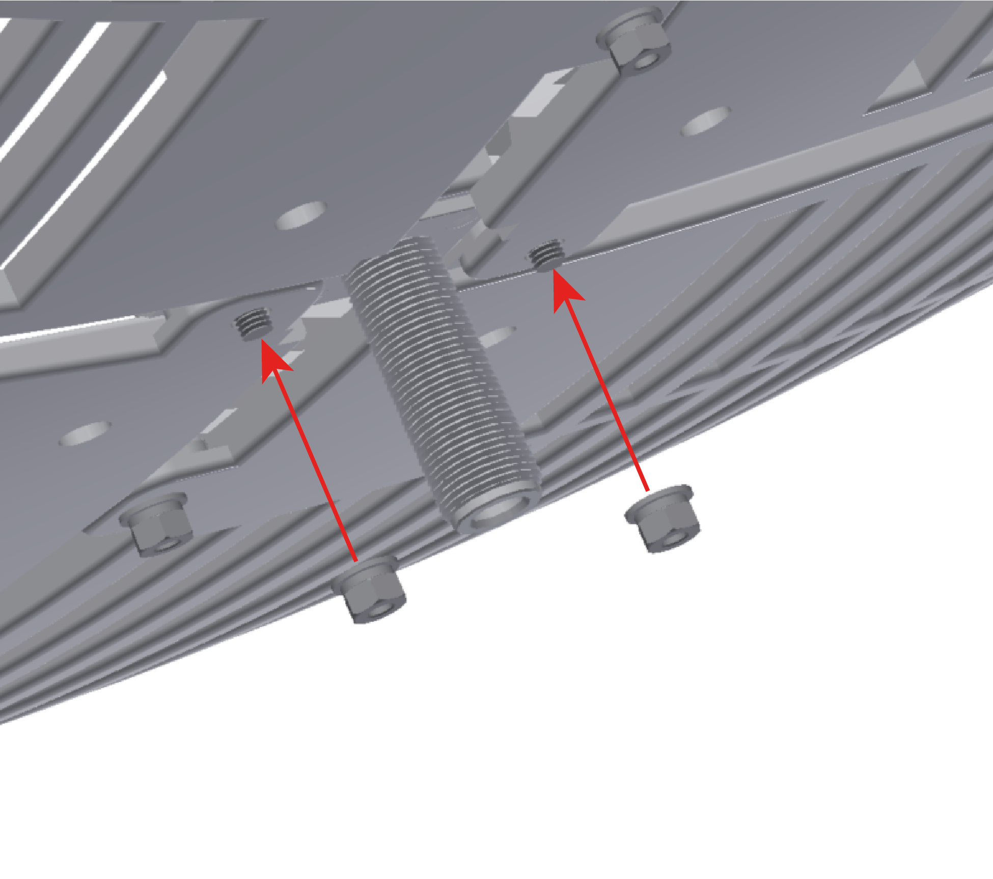
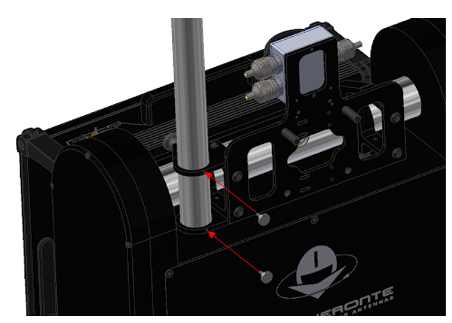
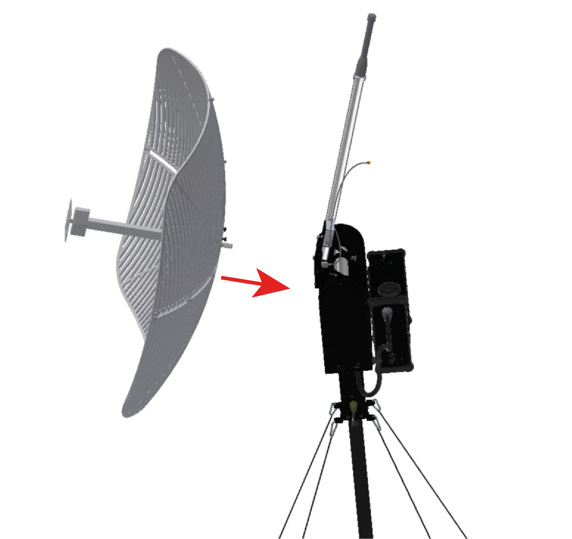
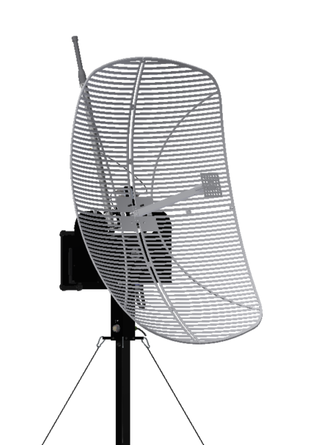
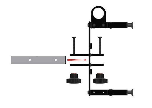
4. Place the parabollic antenna on the Veronte tracker, so the two upper screws on the tracker are inserted into the antenna. It can be placed with 90 degrees angle in case of desiring to change the polarity direction. This direction is indicated by an arrow on the antenna.
Placing antenna
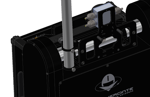
Fitting antenna
Turned 90 degrees
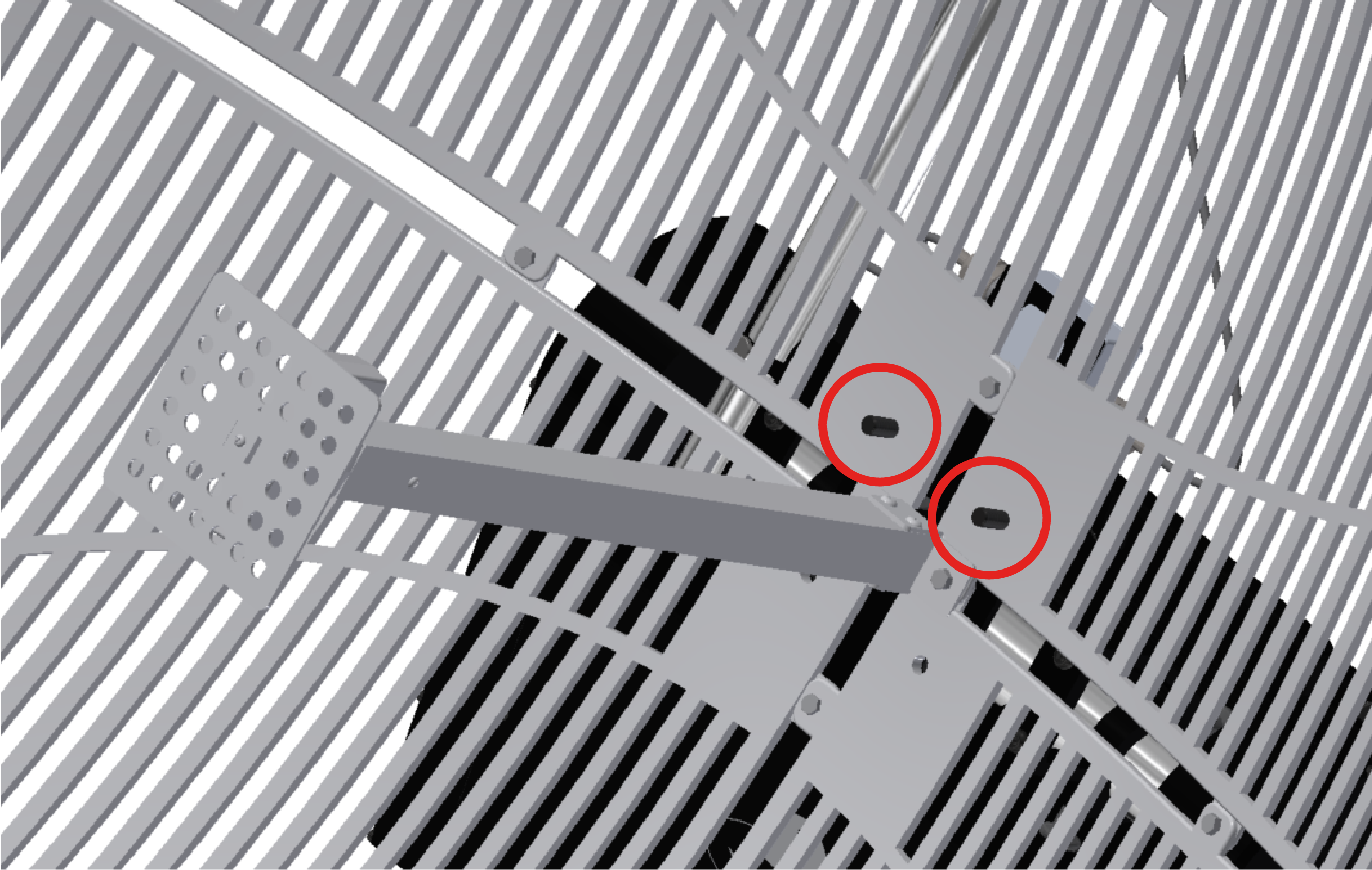
Fix the Parabolic Grid Antenna with the four lobe knobs.
The next image illustrates the final configuration.
Yagi Antenna
Insert the Yagi Antenna into the gap prepared for that purpose. It can be placed with two different angles depending on the polarity direction. This direction is indicated by an arrow on the antenna.

Orientation options
Inserting antenna
Insert the screws through the holes and fix the antenna with the two lobe knobs.

The next image illustrates the final configuration.
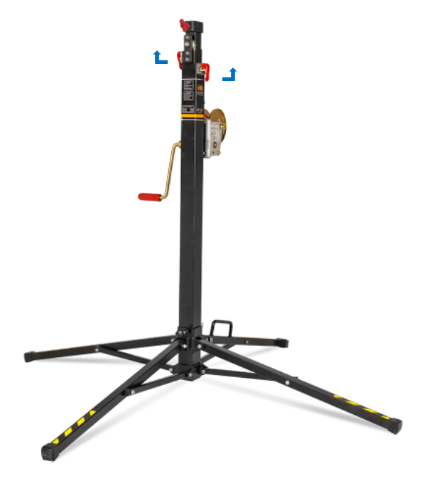
Mast extension instructions
To extend the mast, please follow next instructions.
Loose the Mast fasteners.
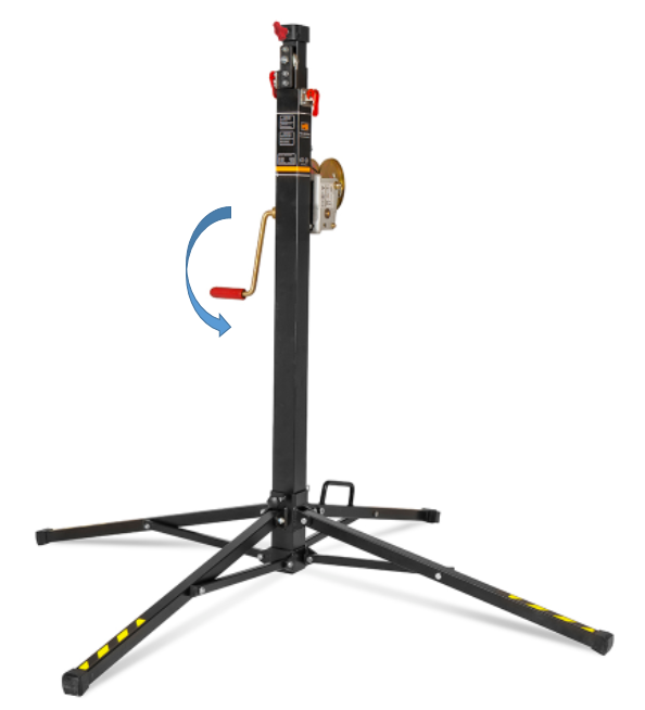
Turn the crank to adjust the height.
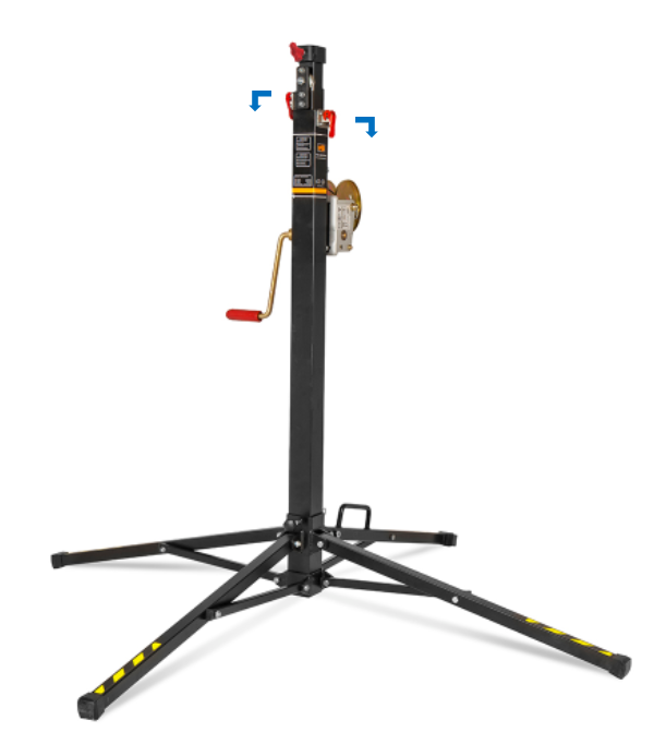
Lock the Mast fasteners.
Guy cable installation
Veronte Tracker is supplied with 4 guy cables and 4 stakes to provide extra stability when mounted.
The use of the guy cables is mandatory when Veronte Tracker rises more than 2.5m although it is always recommended, even more in windy days.
Attach the carabiners as shown in the picture.
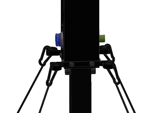
Carabiners installation
Next picture defines the recommended distance between stakes.
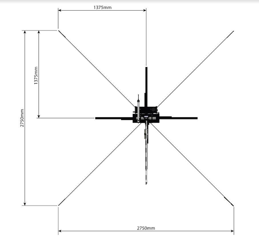
Stakes distances
Once the stakes are installed, the guy cables need to be tightened.
The next image illustrates how to tight and lose the guy cable.
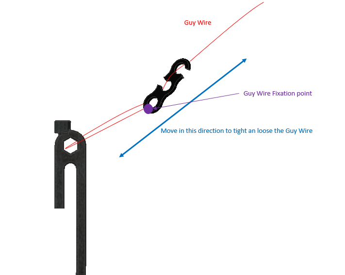
Tight and lose guy cables