Integration examples
Wiring connection
Point to point

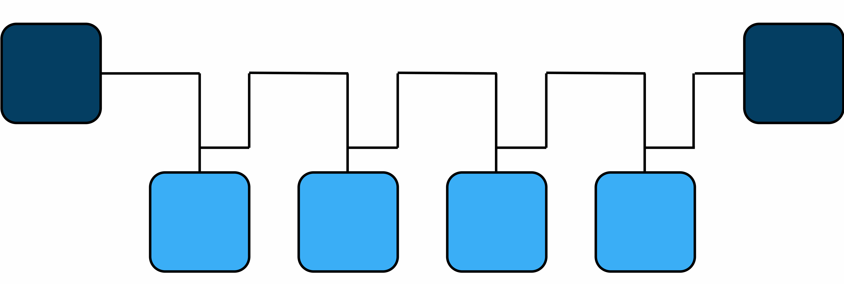
Daisy chain
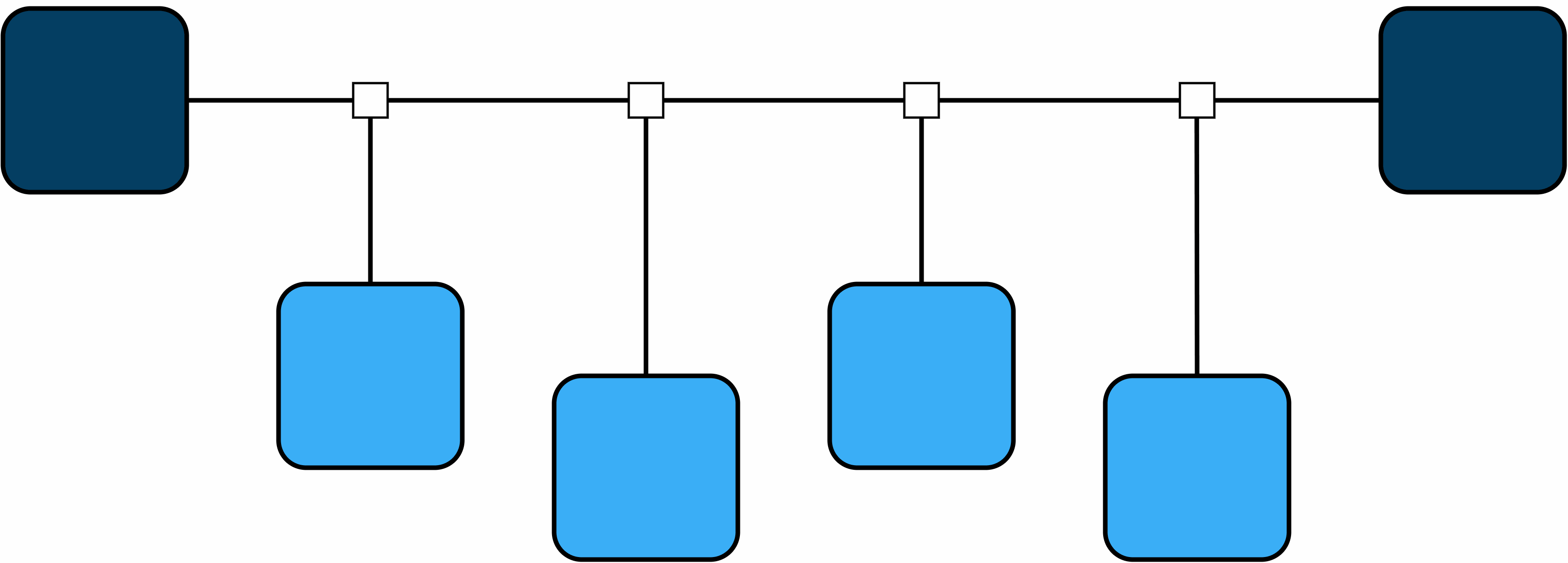
Backbone with stubs
RS232
Point to point
This connection is recommended to establish with the computer while 1x is commanding via CAN to Veronte MC110 or Veronte MC24, since the USB connection between the PC and the 1x may be lost.
RS-232 connection
Note
Transmitter pin (TX) of one device is connected to the receiver pin (RX) of the other one, and vice versa.
RS485/422
Point to point
This connection is recommended to establish with the computer while 1x is commanding via CAN to Veronte MC110 or Veronte MC24, since the USB connection between the PC and the 1x may be lost.

RS-485 connection
Note
Output pin (OUT) of one device is connected to the input pin (IN) of the other one.
Inverted signals (N) are connected each other; in the same way non-inverted signals (P) are linked each other.
Daisy chain
This section details the technical considerations that must be taken into account when connecting the Autopilot 1x to a chain of devices via RS485/422.
Full duplex
Autopilot 1x includes an internal resistor of 120 \(\Omega\). A second resistor is required at the end of the line (again 120 \(\Omega\)) to allow the connection of multiple devices to the same line. This resistor may be placed on cable or PCB.
Full Duplex allows devices on an RS485 network to transmit and receive data simultaneously, enabling continuous bidirectional communication. This mode uses four wires, two for sending and two for receiving, which facilitates faster and more efficient data transfer.
The following diagram shows how to connect the devices:
Half duplex
Half Duplex allows devices on an RS485 network to transmit and receive data, but not at the same time. In this mode, communication alternates between sending and receiving, using only two wires for both directions.
The following diagram shows how to connect the devices:
Warning
The following mode of connection should be avoided.
CAN
Electrical diagram of CAN bus
Autopilot 1x includes an internal resistor of 120 \(\Omega\). A second resistor is required at the end of the line (again 120 \(\Omega\)) to allow the connection of multiple CAN Bus devices to the same line. This resistor may be placed on cable or PCB.

CAN assembly example diagram
Point to point
CAN connection
Note
The user has the option to configure either of the two available CAN BUS lines on the Autopilot 1x: CAN A or CAN B.
The following sections detail the technical considerations to be taken into account when connecting the Autopilot 1x to a chain of devices via CAN.
Daisy chain
The daisy chain connection is the most common and recommended method for interconnecting multiple devices in a CAN system. This procedure involves sequentially connecting the CAN cable from one device to the next, ensuring that the total cable length is minimized to optimize network performance and reduce potential interference.
The following diagram illustrates an example of how to connect devices using this method:
Important
A resistor has been included in the diagram, which allows the connection of more devices, as explained in the Electrical diagram of CAN bus section.
Note
The standard designation for CAN lines in devices is typically CAN H (High) and CAN L (Low). These designations correspond to those of the Autopilot 1x, where CAN P (Positive) and CAN N (Negative) represent the High and Low lines, respectively.
Note
The user has the option to configure either of the two available CAN BUS lines on the Autopilot 1x: CAN A or CAN B.
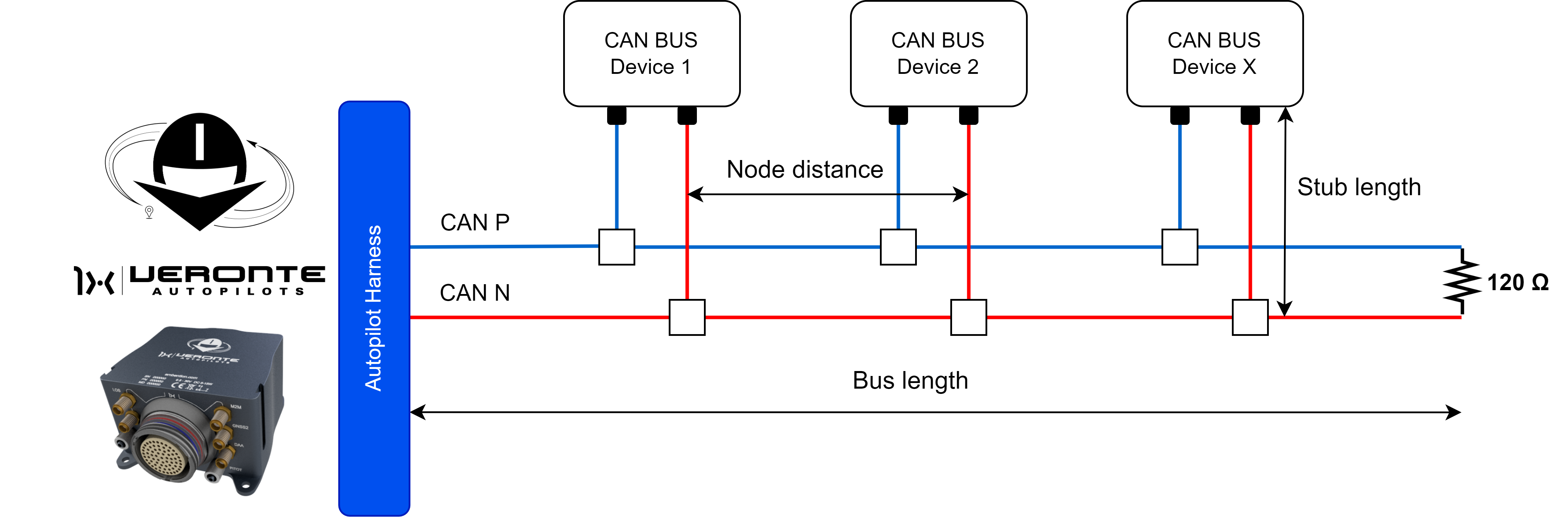
Backbone with stubs
Another method for connecting devices via CAN is to use a master cable from which the necessary stubs will be made to connect the devices. This connection method allows the creation of stubs from the master cable to integrate each device into the CAN network.
It is important for the user to note that when connecting devices in this topology, the total length of the CAN BUS cable is limited. Exceeding this length may adversaly affect network performance and communication integrity.
The following diagram illustrates an example of how to connect devices using this method:
Important
To create stub branches from the master line, T-connectors or CAN splitter are required.
These connectors enable the connection of a device while allowing the main BUS line to continue, facilitating the connection of additional devices.
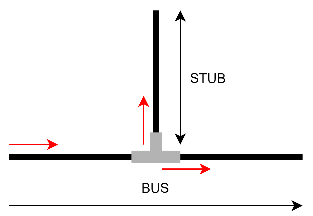
The CAN protocol specifications limit the distance a device can be placed from the BUS. The following table shows the distance limitations to be considered when setting up the system.
Bus Speed |
Bus length |
Stub length |
Node distance |
|---|---|---|---|
1 Mbit/Sec |
40 meters |
0.3 meters |
40 meters |
500 kbits/Sec |
100 meters |
0.3 meters |
100 meters |
100 kbits/Sec |
500 meters |
0.3 meters |
500 meters |
50 kbits/Sec |
1000 meters |
0.3 meters |
1000 meters |
Warning
If a cable stub (un-terminated cable) or a T-connector is used to connect to the bus line, then the stub distance should not exceed 0.3 meters.
Serial to Ethernet Converter
This section provides the process to follow to integrate a Serial to Ethernet Converter, with Veronte Autopilot 1x. In this example, WIZ108SR and WIZ107SR converters are used.
These protocol converters transmit the data sent by serial equipment as UDP data type, and converts back the UDP data received through the network into serial data to transmit back to the equipment.
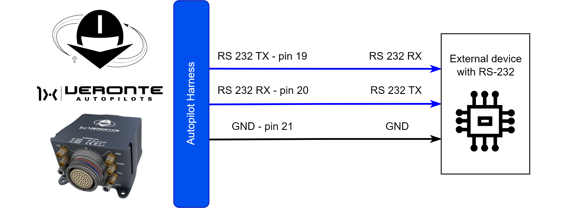
WIZ107SR connection diagram:
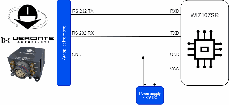
WIZ107SR - Autopilot 1x wiring diagram
Important
To ensure correct operation of the device, use an external power supply and not to connect it to the 3.3 line of Autopilot 1x.
Please note that it shares signal ground with Autopilot 1x.
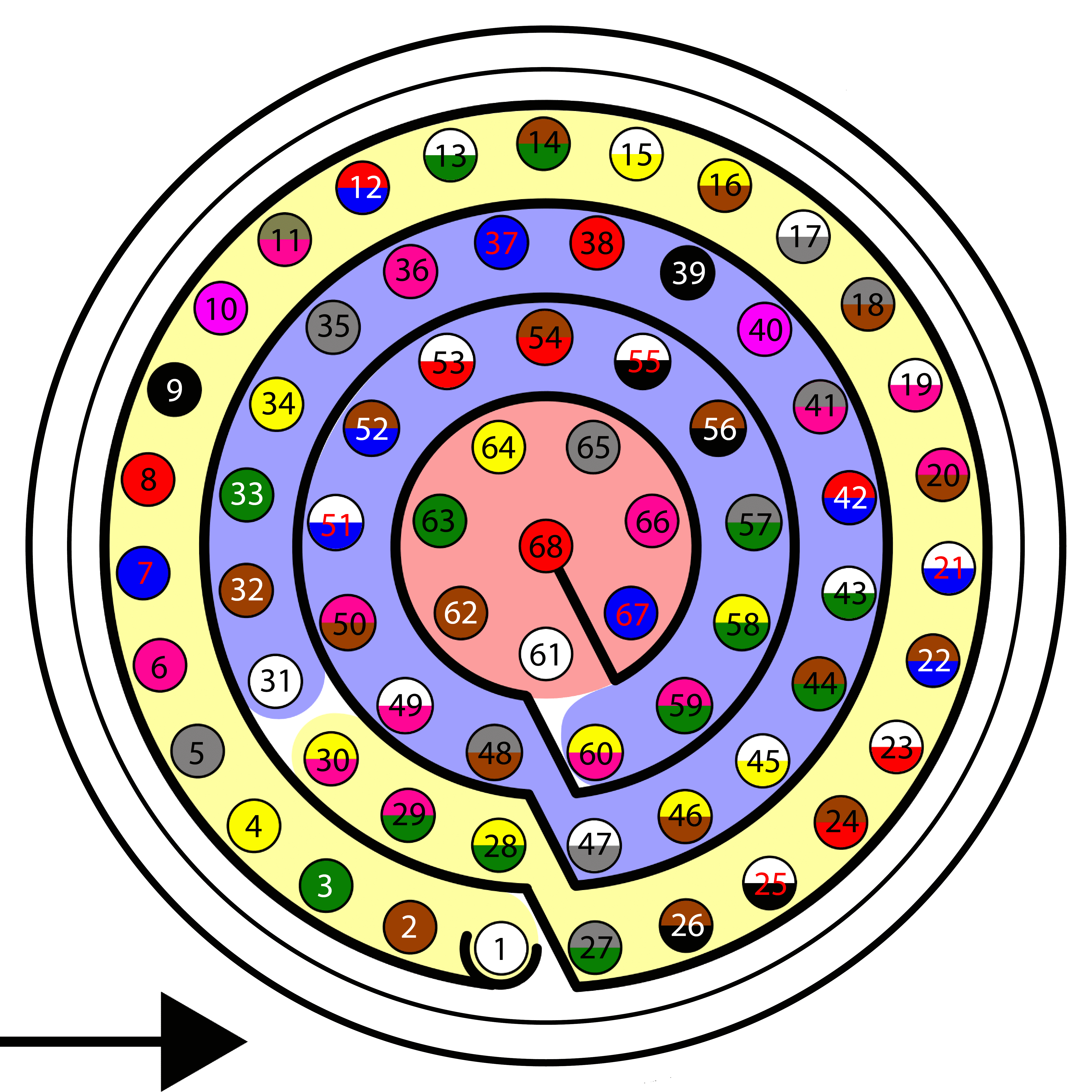
Autopilot 1x harness pinout
Autopilot 1x harness
WIZ107SR Connector
PIN
Signal
Color code
PIN
Signal
19
RS 232 TX
White-Pink
3
RXD
20
RS 232 RX
Pink-Brown
7
TXD
21
GND
White-Blue
11 / 12
GND
Warning
Remember!! In Autopilot 1x, all GND pins are common. Note that pin 54 is not a common GND pin.
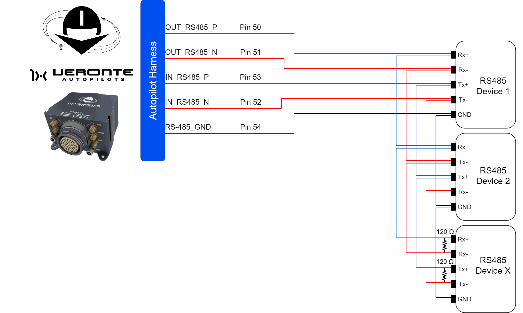
WIZ108SR connection diagram:
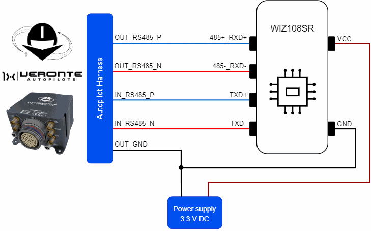
WIZ108SR - Autopilot 1x wiring diagram
Important
To ensure correct operation of the device, use an external power supply and not to connect it to the 3.3 line of Autopilot 1x.
Please note that it shares signal ground with Autopilot 1x.
Autopilot 1x harness pinout
Autopilot 1x harness
WIZ108SR Connector
PIN
Signal
Color code
PIN
Signal
50
OUT_RS485_P
Pink-Brown
3
485+_RXD+
51
OUT_RS485_N
White-Blue
5
485-_RXD-
53
IN_RS485_P
White-Red
7
TXD+
52
IN_RS485_N
Brown-Blue
9
TXD-
54
OUT_GND
Brown-Red
11 / 12
GND
Warning
Note that this pin 54 is not a common GND pin.
Note
This integration is done for the WIZ108SR, this is for a connection via RS485 with Autopilot 1x. However, the process for the WIZ107SR device is almost the same.
Once the hardware installation is complete, follow the steps below to properly configure the connection and ensure stable communication between the devices.
Ethernet Connection in Windows
First, make sure computer is set to static IP address on same subnet as radio. The following substeps clarify how to set the IP address:
Connect the Ethernet cable of the WIZNet adapter, powered by 3.3V, to the Ethernet port of the PC.
Open Network and Sharing Centre menu and click Change adapter settings.
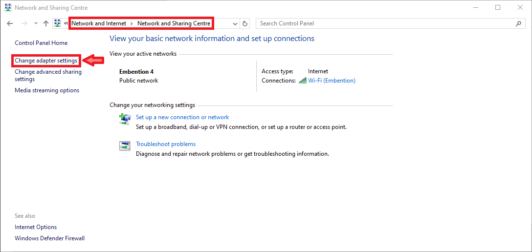
Ethernet connection 1
Select Local Area Connection, right click, and select Properties.
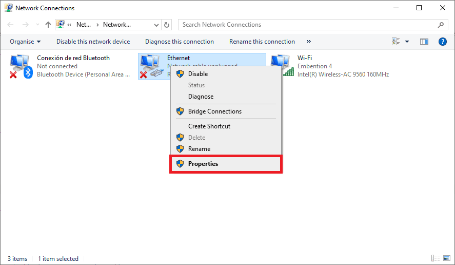
Ethernet connection 2
Select IPv4 and click Properties.
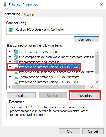
Ethernet connection 3
Set IP address to 192.168.11.X (in this example
192.168.11.8is entered) and Subnet mask to255.255.255.0. Click OK.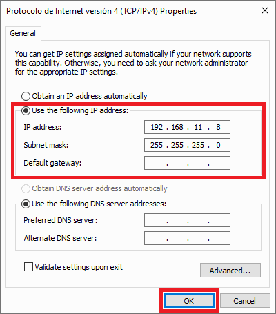
Ethernet connection 4
WIZNet software configuration
Open the WIZNet Software and select the Ethernet port with the IP assigned before in the dropdown menu.
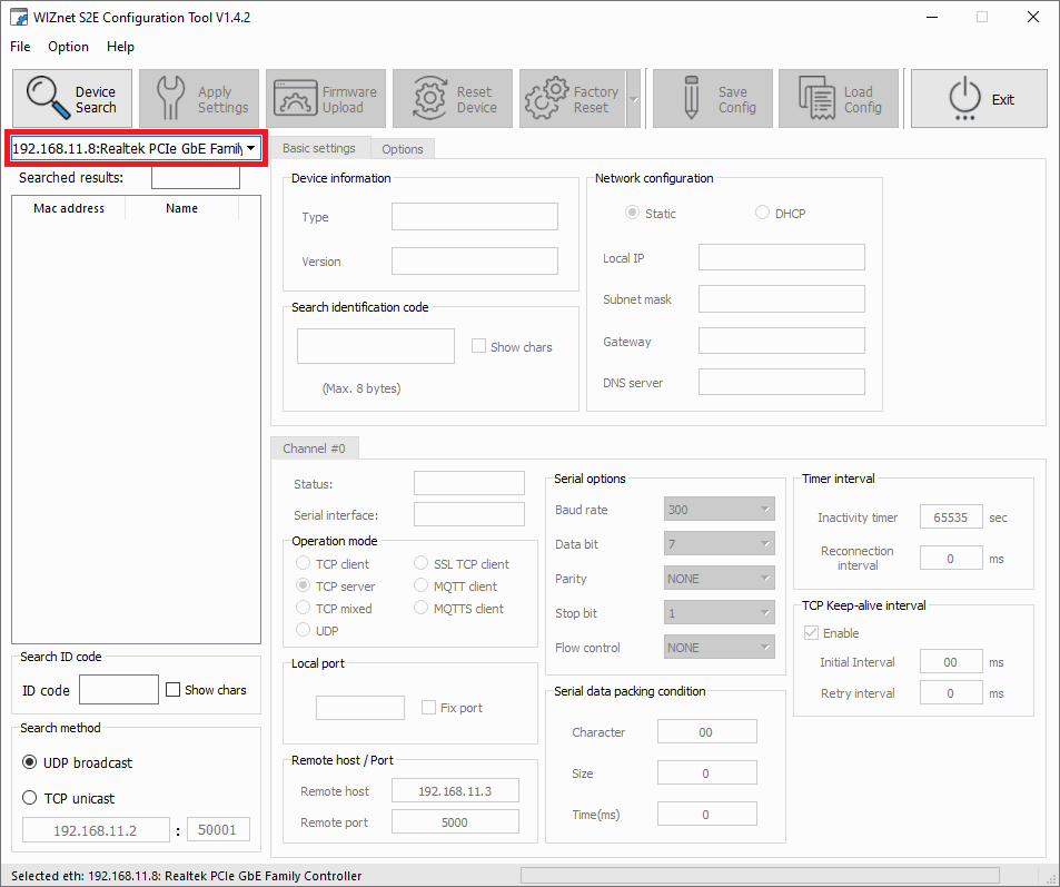
WIZnet software - Ethernet port selected
Click on the Device Search option to scan for the device.
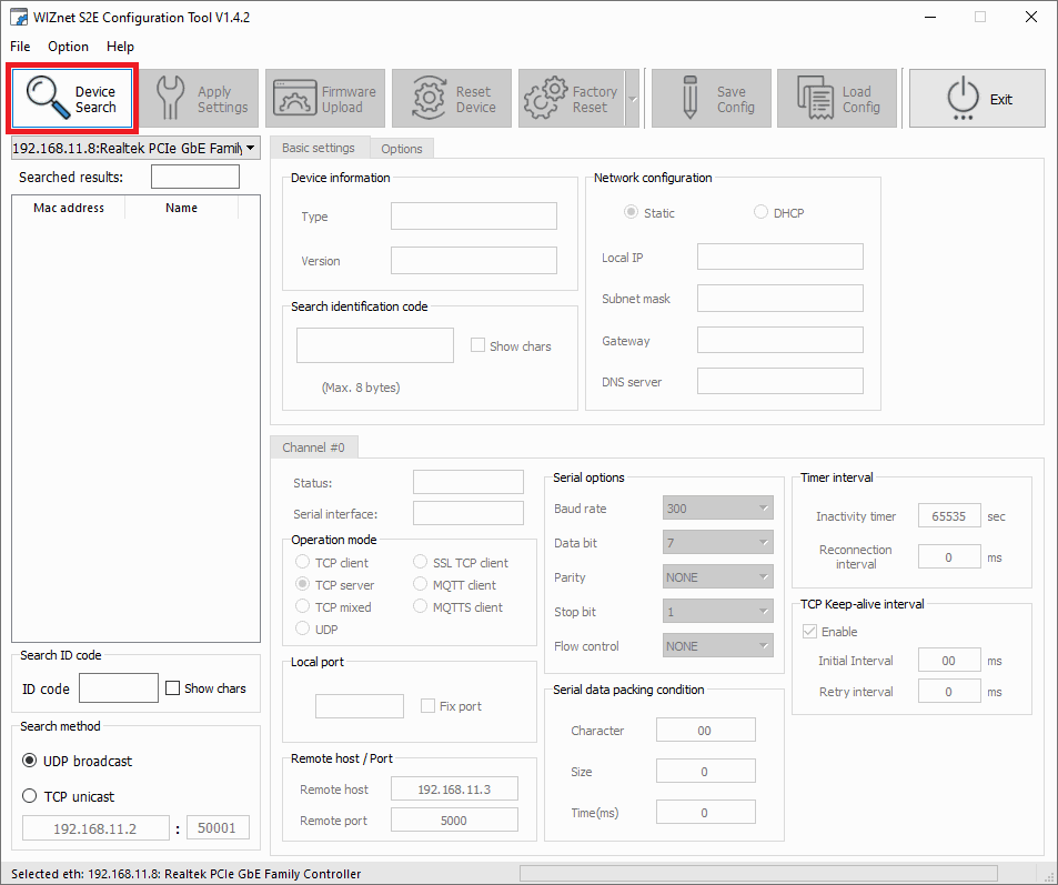
WIZnet software - Scan for device
Then, if the module is properly connected to the network, it will appear in the search list. Select the WIZ108SR device to access its configuration.
Caution
If the module does not appear in the list and it has been previously connected to another PC, reboot the module (simply unpower it and power it up again).
This is because when the WIZ108SR module establishes a connection to a PC’s MAC address, it will only communicate with that PC unless it is rebooted.
The configuration must be as follows:
In the Basic Settings tab, make sure that the Network Settings parameters are:
Local IP:
192.168.11.2Subnet Mask:
255.255.255.0Gateway:
192.168.11.1
In the Channel #0 tab:
Change the Operation mode to UDP.
Set the Local port to
5001(for example).Set the Remote host to the adapter IP previously configured in step 5 and a Remote Port, in this example port
5002has been chosen.The Serial options must match those of the Autopilot 1x, so set them as follows:
Baud rate:
115200Data bit:
8Parity:
NONEStop bit:
1
Modify in the Serial data packing condition the size to
255to send the data in 255 byte packets, so that each send will have more data.
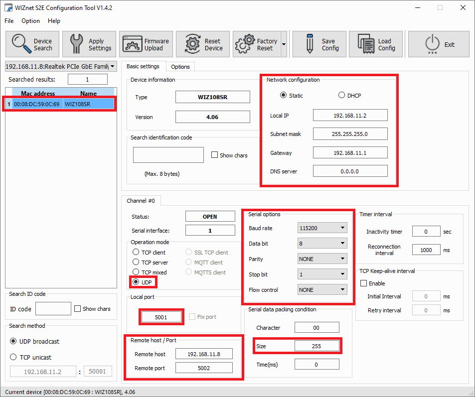
WIZnet software - Device configuration
Finally, click Apply Settings to save the configuration to the device.
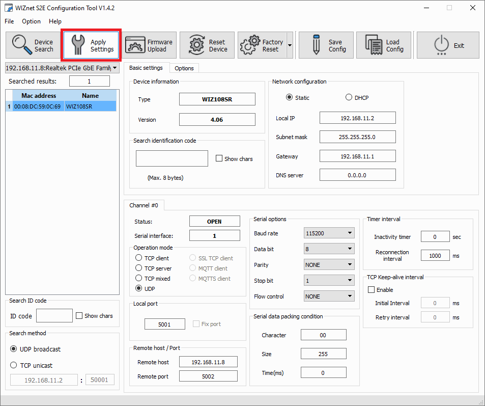
WIZnet software - Apply Settings
Veronte Link configuration
Add a new UDP connection in Veronte Link and configure it with the same IP address and port as previously set in the Remote options of the WIZNet settings.
In this example:
Address:
192.168.11.1Port:
5002
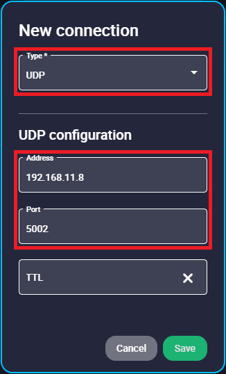
Veronte Link - Connection settings
For more information on Veronte Link connections, please refer to the UDP connection - Integration examples section of the Veronte Link user manual.
1x PDI Builder configuration
Go to Input/Output menu \(\rightarrow\) I/O Setup panel.
Bidirectionally connect the RS485 Producer to a Commgr port Consumer, in this example it has been linked to Commgr port 3. Then, the same Commgr port Producer, in this case Commgr port 3, should be automatically connected to the RS485 Consumer:
Note
If the WIZ107SR module is used, i.e. a connection is established via RS232, bidirectionally connect the RS232 port to a Commgr port and not the RS485 port.
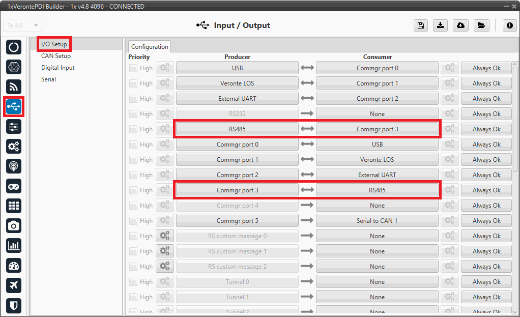
1x PDI Builder - I/O Setup configuration
Go to Input/Output menu \(\rightarrow\) Serial panel \(\rightarrow\) RS485 tab.
Note
If using the WIZ107SR module, check the RS232 parameters instead.
Make sure that these parameters are the same as the parameter values previously set in the WIZNet software.
Baudrate: 115200
Length: 8
Stop: 1
Parity: Disabled
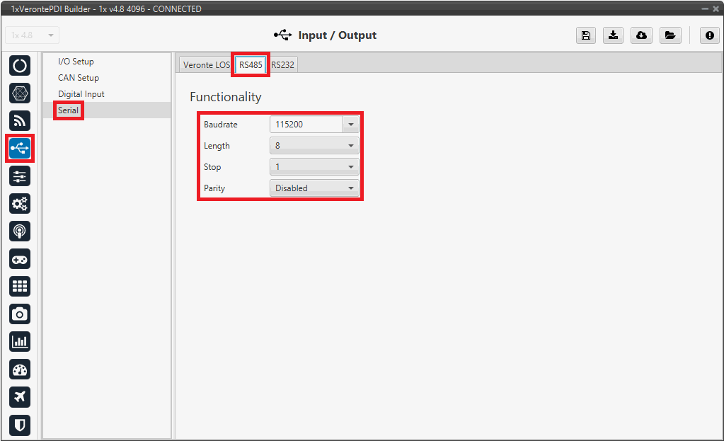
1x PDI Builder - Serial configuration
Following these steps, Autopilot 1x should appear in Veronte Link as follows:
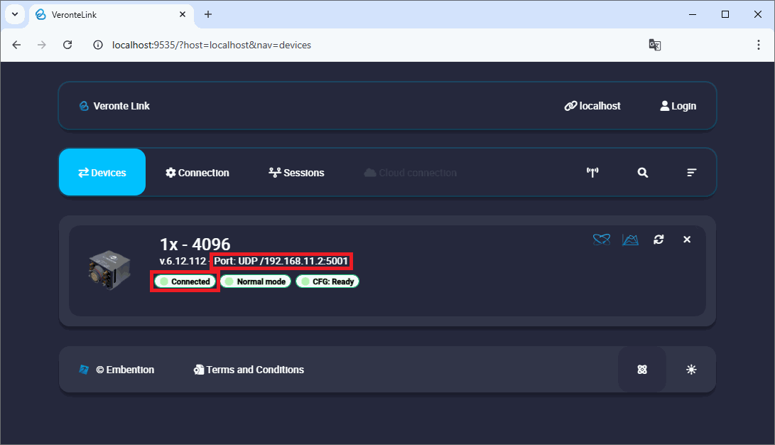
Autopilot 1x connection via UDP
External devices
The step-by-step instructions for the following external devices will be explained in detail in the following sections: