Integration examples
UDP connection
Wi-Fi/Ethernet connection
Open 1x PDI Builder and check the following settings:
-
The RS485 port must be connected to the Commgr port, in this example, it's connected to Commgr port 4. Conversely, the same Commgr port, in this example Commgr port 4, must be connected to the RS485 port.
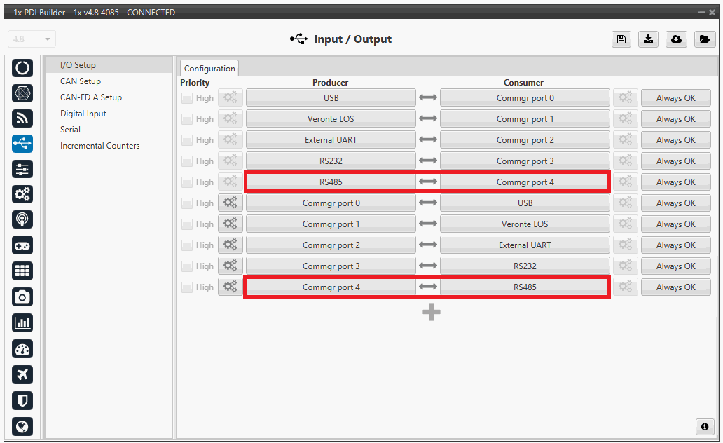
IO setup - Settings -
In the RS485 section, the Baud rate must have the following value.
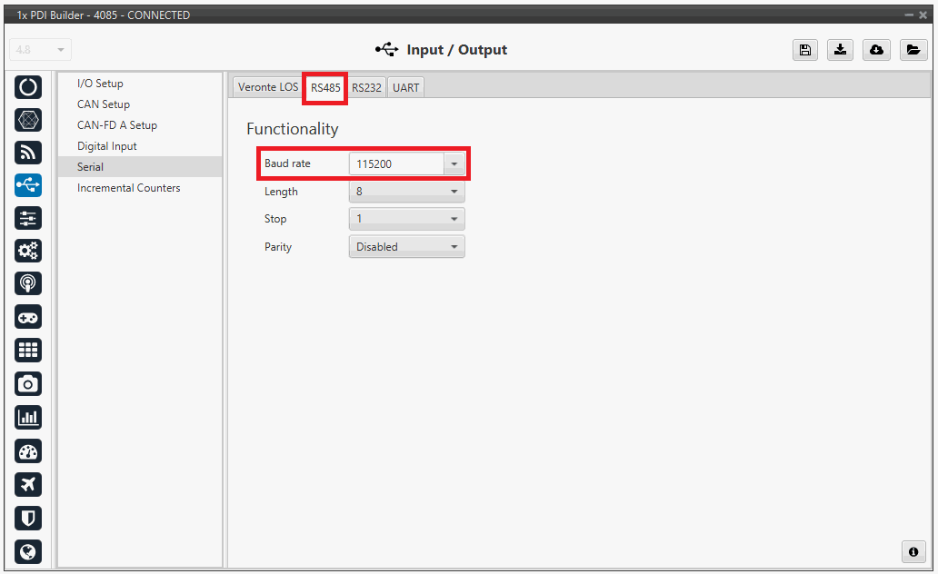
RS485 - Settings
Warning
If the device is being connected for the first time, it is necessary to connect it via Ethernet. Afterwards, it is possible to disconnect the Ethernet and confirm that it works via SERIAL.
Wi-Fi/Ethernet configuration
The following steps are applied to a PCS unit as an example.
Important
If connecting through Ethernet, step 1 does not apply.
- The first step is to look under available networks for the PCS unit and connect to it.
-
Once the connection is made, enter Veronte Link and configure the UDP connection in the Connection menu.
First, click on "+":
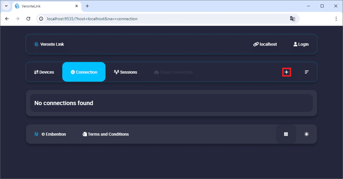
Add new connection -
Then, the configurable parameters must be entered.
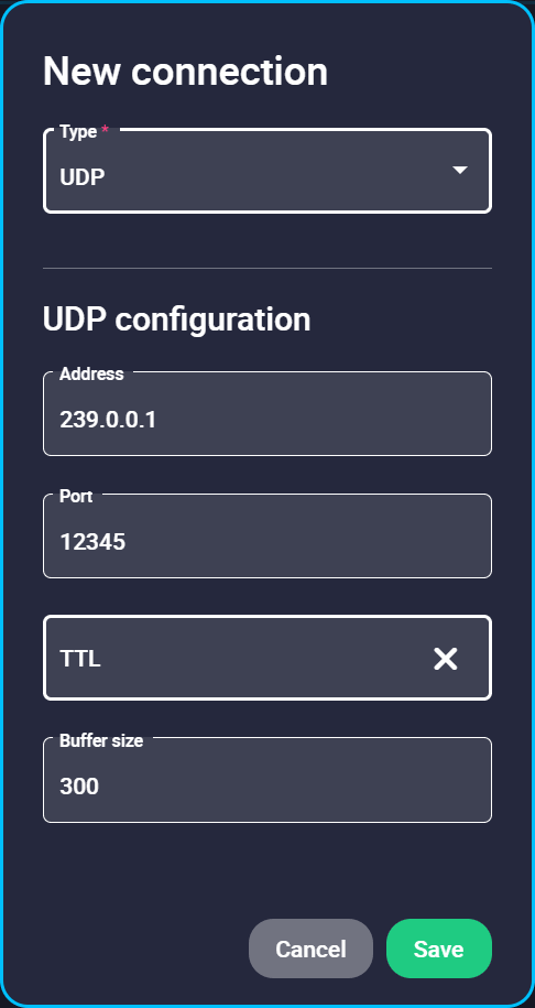
New UDP connection configuration Important
This address and port are configured for this PCS unit, they do not have to be the same for another device.
-
Finally, if the configured connection is correct and everything went well, a new PCS will appear in the device list and the device status will change to PDIF: Ready. The user is ready now to start configuring the PCS using 1x PDI Builder.

PCS unit correctly connected
Note
The image of a Veronte Autopilot 1x is displayed and not a PCS as the device that is actually connected is the Autopilot 1x inside the PCS.
TCP-SERVER connection
Ethernet configuration
The following steps detail how to connect Veronte Link to an Autopilot 1x via a TCP connection to a Microhard radio.
Note
In this connection, the radio acts as "Client" and Veronte Link as "Server".
-
Configure, in the Microhard WebUI, the radio as "TCP Client" and enter the following parameters:
- Remote Server IP Address: IP address of the PC.
- Remote Server port: TCP port to which the radio has to connect. It must be the same as the one configured in Veronte Link.
For more information on the radio configuration, users can refer to the Microhard radio configuration - Integration examples section of the 1x Hardware Manual or directly to the Microhard radio documentation.
-
Connect Veronte Autopilot 1x to the Microhard radio via RS232 as detailed in the Microhard pDDL900-ENC external - Integration examples section of the 1x Hardware Manual.
-
Once the configuration and connection is done, open Veronte Link and configure the TCP-SERVER connection in the Connection menu.
First, click on "+":
Add new connection -
Then, the configurable parameters must be entered.
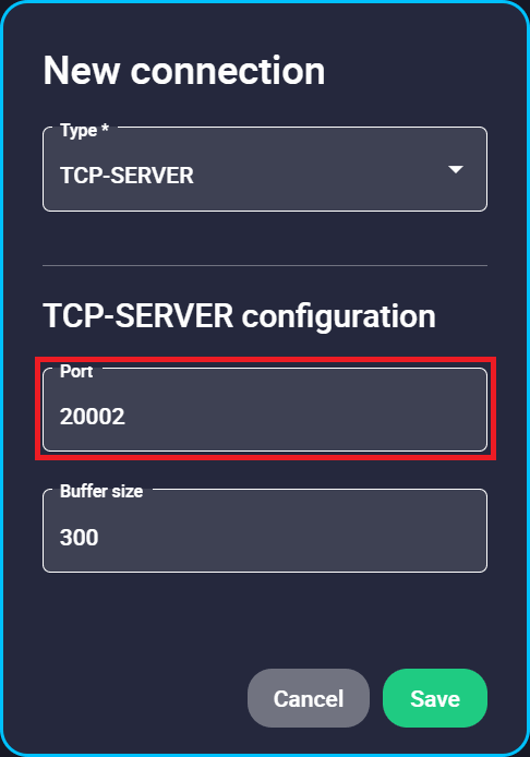
New TCP-SERVER connection configuration - Port: Enter a TCP port to which the radio will be connected, the same as the one previously configured as "Remote Server port" in the radio configuration.
-
Finally, if the configured connection is correct and everything went well, a new Autopilot 1x will appear in the Devices list. It should look like this:
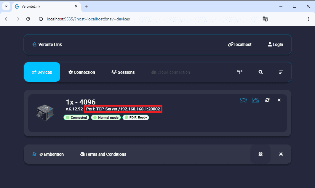
1x unit correctly connected
TCP-CLIENT connection
Ethernet configuration
The following steps detail how to connect Veronte Link to an Autopilot 1x via a TCP connection to a Microhard radio.
Note
In this connection, the radio acts as "Server" and Veronte Link as "Client".
-
Configure, in the Microhard WebUI, the radio as "TCP Server" and enter a "Local Listening Port" to which Veronte Link will have to connect (usually the default one is used).
For more information on the radio configuration, users can refer to the Microhard radio configuration - Integration examples section of the 1x Hardware Manual or directly to the Microhard radio documentation.
-
Connect Veronte Autopilot 1x to the Microhard radio via RS232 as detailed in the Microhard pDDL900-ENC external - Integration examples section of the 1x Hardware Manual.
-
Once the configuration and connection is done, open Veronte Link and configure the TCP-CLIENT connection in the Connection menu.
First, click on "+":
Add new connection -
Then, the configurable parameters must be entered.
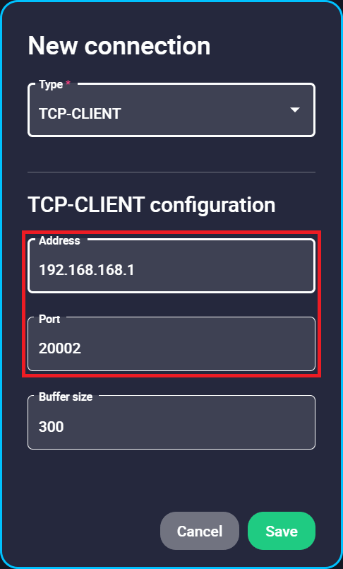
New TCP-CLIENT connection configuration - Address: IP address of the radio.
- Port: Enter as TCP port the "Local Listening Port" previously set in the radio configuration.
Important
This address and port are configured for this radio unit, they do not have to be the same for another device.
-
Finally, if the configured connection is correct and everything went well, a new Autopilot 1x will appear in the Devices list. It should look something like this:
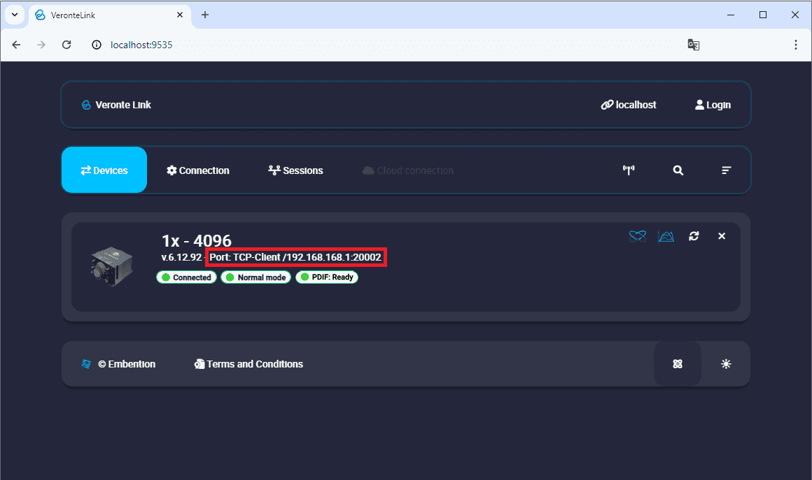
1x unit correctly connected
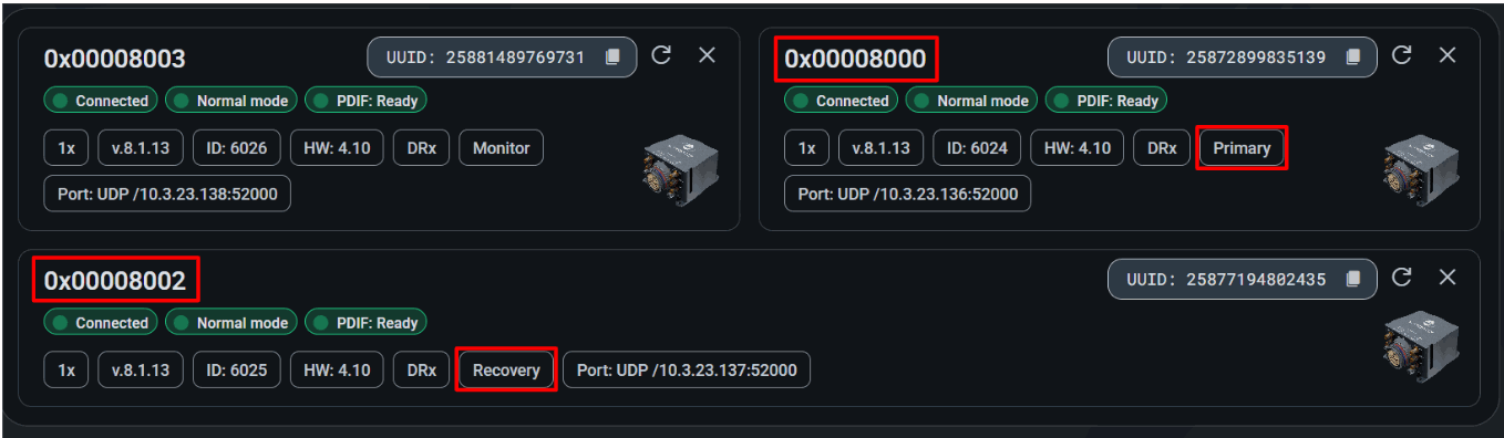
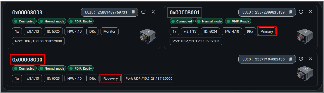
DRx
When connecting the DRX, the three 1x units will be displayed. These units feature sequential serial numbers.
The identifier of the unit currently in command (Primary or Recovery) is subject to change: the serial number of the unit in command is modified in its first digit based on the current command status.
© 2026 Embention. All rights reserved.