Devices blocks
Devices connected to Autopilot 1x and a clock can be configured with these blocks.
Clock
Clock block computes the time elapsed since the last reset or since the last step execution (depending on the block configuration).

Clock block
Input
 (Optional) Reset: The clock is reset when the input value is TRUE. Assumes FALSE if unconnected.
Output
 Time: Computed time in seconds.
Configuration menu:
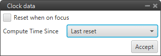
Clock block configuration
Reset when on focus: If enabled, the clock will be reset the first time it is executed.
Compute Time Since: The available options are:
Last reset: The block acts as a ‘normal clock’, counting the time since it was started/restarted.
Last step: Time elapsed since the program, in which the block is added, was executed.
Gimbal
Gimbal block is a gimbal device controller that uses current navigation estimation.
It allows users to configure a Gimbal Camera by defining the movements the system has (from predefined combinations of Pan, Tilt and Roll), its logic and a distance vector.
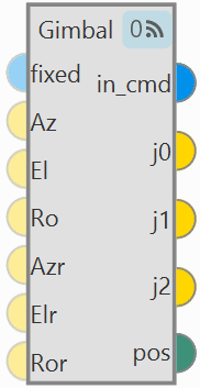
Gimbal block
Inputs
(Optional) fixed: Mode of operation: - If TRUE the gimbal is in absolute orientation mode and uses the inputs ‘Az’, ‘El’ and ‘Ro’. - If FALSE the gimbal is in arcade mode and uses the inputs ‘Azr’, ‘Elr’ and ‘Ror’. - If not connected assumes FALSE. (Optional) Az: Desired azimuth. This input is only used when ‘fixed’ input is TRUE. Assumes zero if not connected. (Optional) El: Desired elevation. This input is only used when ‘fixed’ input is TRUE. Assumes zero if not connected. (Optional) Ro: Desired roll. This input is only used when ‘fixed’ input is TRUE. Assumes zero if not connected. (Optional) Azr: Desired azimuth rate. This input is only used when ‘fixed’ input is FALSE. Assumes zero if not connected. (Optional) Elr: Desired elevation rate. This input is only used when ‘fixed’ input is FALSE. Assumes zero if not connected. (Optional) Ror: Desired roll rate. This input is only used when ‘fixed’ input is FALSE. Assumes zero if not connected.
Outputs
in_cmd: Has a value of TRUE when the gimbal block is being externally commanded, FALSE otherwise. j0: Gimbal joint 0 angle in radians. This is the desired Pan angle. j1: Gimbal joint 1 angle in radians. This is the desired Tilt angle. j2: Gimbal joint 2 angle in radians. This is the desired Roll angle. pos: Position in the surface of the Earth where the gimbal is pointing to.
Configuration menu:
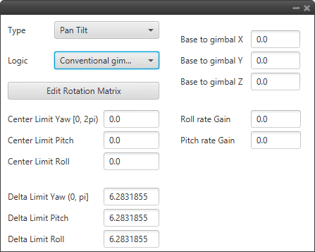
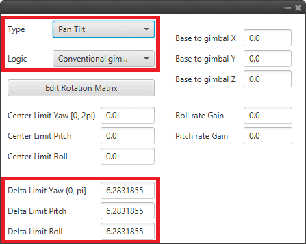
Gimbal block configuration
The following parameters must be configure:
Type: Defines the angles that the Veronte Autopilot 1x will control from the payload system from a combination of Pan (Z-axis, same as Yaw), Tilt (Y-axis, same as Pitch) and Roll.
The three options available are:
Pan & Tilt
Pan, Roll & Tilt
Roll & Tilt
Logic: Defines the kind of payload system configured:
Conventional gimbal: This option writes over the variables Joint 1-3 of Gimbal 1-3 which are used later to configure camera control and stabilization from Autopilot 1x.
Self-stabilized gimbal: The payload system only needs movement inputs and the variables mentioned will have no output.
Base to gimbal X/Y/Z: Defines the vector linking Veronte Autopilot 1x controlling the payload system and the payload system itself, on Veronte body axes.
Edit Rotation Matrix: Matrix to rotate the system to match the aircraft coordinate system.
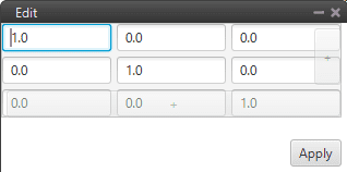
Gimbal block configuration - Rotation Matrix
Center Limit Yaw [0, 2pi]/Pitch/Roll: Center of the range of movement.
Delta Limit Yaw [0, pi]/Pitch/Roll: That is how much the gimbal can move in positive and negative from the center defined above.
Note
This part of limit is because there are some gimbals that cannot make a full turn on some axis.
Roll/Pitch rate Gain: Gains to compensate for roll rate or pitch rate inputs.
An example of use is given below:
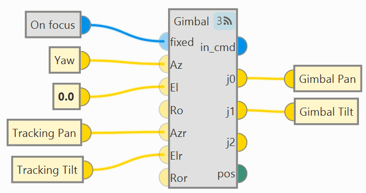
Gimbal block - Example of use
Gimbal block - Configuration example
Stick
Stick block is a stick reader, with it the user can configure the stick parameters for manual and arcade modes.
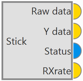
Stick block
Warning
This block is mandatory for the use of the transmitter. For more information on the stick configuration, see the Stick - Integration examples section of this manual.
Outputs
Raw data: Raw stick channels. Y data: Stick channels after transformation (matrix and offset). Status: TRUE if the stick is read without timeouts, FALSE otherwise. RXrate: Stick update frequency rate (Hz).
Configuration menu:
Sources: In this tab the user can set multiple transmitter inputs with the respective priority, from top to bottom.
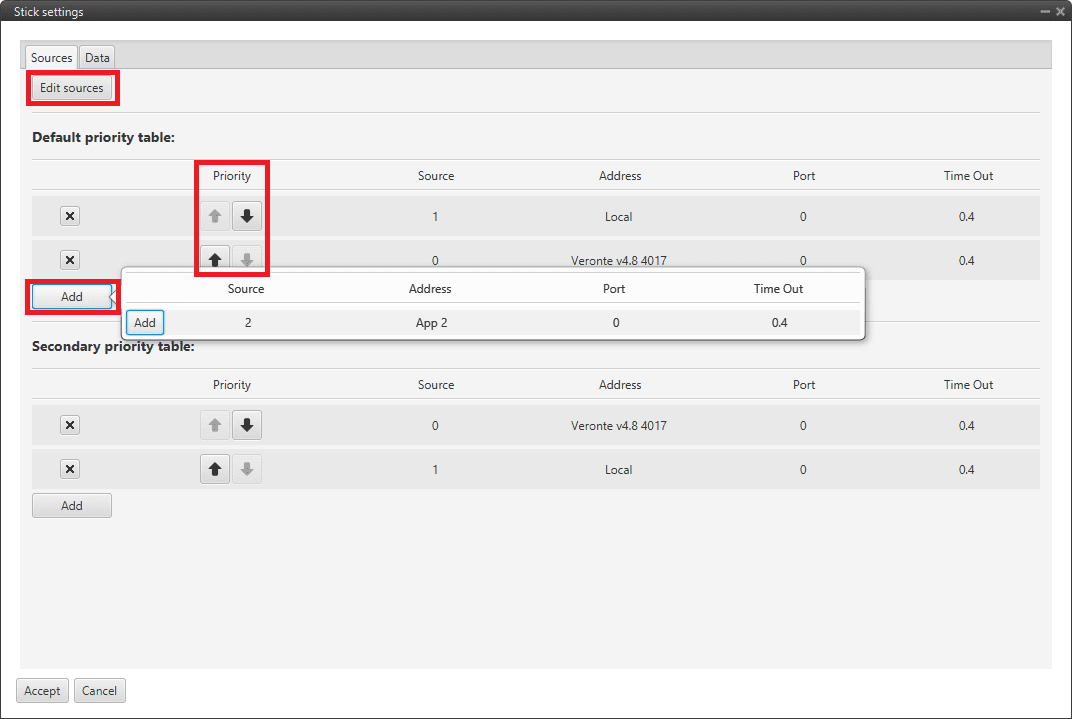
Stick block configuration - Sources
Priority table: By default, one priority table is set. The user can configure a second one.
Priority: Use arrows to determine the priority of the selected source. Priority is set from top to bottom.
Add: An already defined source can be added to the priority table.
Edit sources: New sources can be defined in this menu.
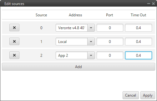
Edit sources menu
Source: It is the order in which sources are created in this menu. This does not set the priority.
Address: This defines the source from which the stick information is taken from. The following options are the most common:
App 2: Means that the information is coming from the stick widget of Veronte Ops.
Local: Represents the actual selected autopilot (i.e. the transmitter is connected to it).
Any: The information comes from all linked autopilots.
1x v4.X XXXX: Means the information is coming from a particular autopilot, which needs to be visible in Veronte Link.
For more information on the available addresses, see List of addresses section of the 1x Software Manual.
Port: From each source it is posible to have more than one stick information, e.g. two transmitters can be connected to the same autopilot. The port is an identifier to distinguish them.
Time Out: This defines the time to consider the source inactive. Therefore the incoming stick information will be always the one from the source with higher priority and active. Once it is considered inactive the following active source will send its stick information. The lower this value, the more frequent the stick will be lost. We recommend a value of 0.4 s.
Data: In this tab the user can configure \(Mix \, Matrix, Raw \, channels\) and \(Offset\).
The movement that the pilot makes on the stick produces variations on a vector called \((Raw \, channels)\) of length \(n\), where \(n\) goes from 1 to the total number of employed transmitter channels. The values reached by the components of \((Raw \, channels)\) are limited between 0 and 1. These stick movements need to be processed to produce the input signals that will go into the control algorithm, in the case of arcade mode; or directly into the servos for manual mode.
The process begins by mapping each one of the sticks inputs to PWM signals into a vector called \(Output\) of length \(m\), where \(m\) goes from 1 to the total number of actuators.
The full definition of \(Output\) is \(Output = (Mix \, Matrix) \cdot (Raw \, channels) + Offset\), where:
\((Mix \, Matrix)\) is a matrix that transforms raw stick inputs \((Raw \, channels)\) to PWM signals \(Output\).
\(Offset\) is an offset vector, which corrects the \(Output\) vector.

Stick block configuration - Data