Operation
In order to stablish a connection between a Veronte device and a PC with Veronte Link, follow the steps:
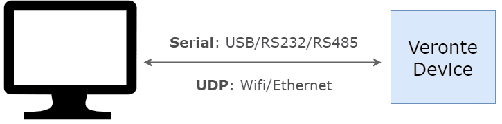
Connect the device to a PC via Serial (USB, RS232 or RS485) or UDP (Wifi or Ethernet).
PC-Veronte device connection
Note
Connecting the device to the PC is not necessary when communicating via Veronte Cloud. Please, see Cloud connection for further information.
Open Veronte Link, then a similar image to the following should be displayed:
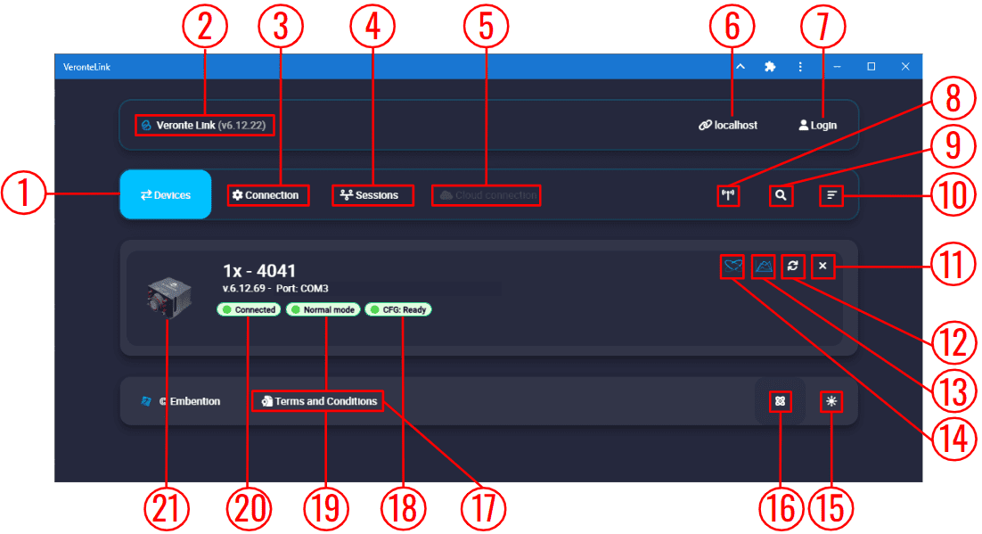
Veronte Link interface - Devices menu
Devices: This is the currently displayed menu. It shows the devices connected to the PC.
Veronte Link version: Informs the user about the version of the software being used.
Connection: This menu allows the user to configure the connection between the PC and a Veronte device. See Connection section for more information.
Sessions: In this menu users can play back recorded logs and flights. See Sessions section for more information.
Cloud connection: This menu allows the user to configure the internet connection between the PC and the available Veronte Autopilots 1x. See Cloud connection section for more information.
Note
Only available if the user has logged in.
Host: Allows connecting to the local IP address or to another desired IP address.
Login: Enables cloud connection through user logging.
Find all: Runs a discovery to all devices.
Search from ID: Searches for a specific device by its ID. Entering the ID 999 will search for all devices.
Sort list: Click on it to sort the list of devices.
Delete device: Only works after disconnecting the device.
Note
Only available if a device is connected or has been connected.
Refresh device: It is recommended to use in case of any connection error.
Note
Only available if a device is connected or has been connected.
Open Veronte FDR: From here users can access Veronte FDR on the same version of the connected device.
Open Veronte Ops: From here users can access Veronte Ops on the same version of the connected device.
Dark/light mode: Switches to light/dark mode, changing the display mode of the interface.
Switch particles: Particles can be on or off, changing the application appearance.
Terms and Conditions: Users can consult the ‘End User License Agreement (EULA)’ by simply clicking on this button.
Configuration status: It can be:
CFG: Waiting to read (only for Veronte Autopilot 1x)
CFG: Reading conf
CFG: Ready
CFG: Failed load conf
CFG: Not Downloaded (for other products than Veronte Autopilot 1x)
CFG: Not compatible
Note
Products are typically operational even if the configuration is not marked as “ready”
Device status: Can be in Normal mode, Maintenance mode or Loaded with errors.
Connection status: It can be Connected or Disconnected.
Veronte device: Here it is displayed an image of the Veronte device that is connected.
Important
Once Veronte Link is executed, an icon will appear in the taskbar and a browser window will open.
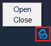
Veronte Link icon
To close the application, it is not enough to close the browser window, it is necessary to right-click on the icon and select Close.
If the browser window is closed, it can be accessed again by selecting the Open button.
Connection
In this menu users must configure the connection type of the Veronte device.
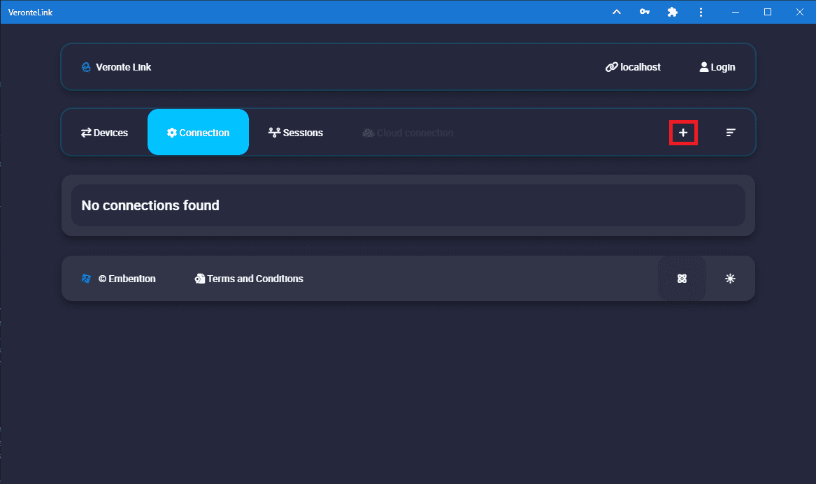
Connection menu
Clicking on the ‘+’ icon will display the configuration panel. The parameters to be configured depend on the type of connection selected:
Warning
Apart from Type and Port parameters, it is not recommended to modify the default configuration, as the default parameters should work correctly.
Serial: USB, RS232 or RS485 connections.
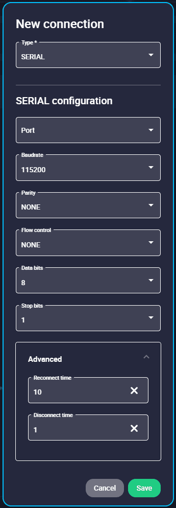
Serial connection configuration
Port: Select the port of the computer to which the device is connected. It does not have to be the same as the one in the example image (Veronte Link interface image).
More information about the port where the device is connected is explained in Serial connection - Integration examples section.
Baudrate: This field specifies how fast data is sent over a serial line.
Parity: Is a method of detecting errors in transmission.
When parity is used with a serial port, an extra data bit is sent with each data character, arranged so that the number of 1 bits in each character, including the parity bit.
The available options are EVEN, MARK, ODD, SPACE and NONE.
Flow Control: RTS/CTS and XON/XOFF control can be configured if needed.
Data Bits: Defines the number of bits in the message. It can be configured from 5 to 8 bits.
Stop bits: Number of stop bits sent at the end of every character. Can be 1, 1.5 or 2.
Advanced:
Reconnect time: The time to consider a device reconnected. Default is set to 10 seconds.
Disconnect time: Time to consider a device disconnected is defined here. 1 second is configured by default.
UDP: Ethernet or Wifi connections.
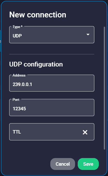
UDP connection configuration
Important
Consider the maximum packet size supported by the Veronte Communication Protocol (VCP) when using serial data converters.
Address: IP address, normally set to 239.0.0.1 (for broadcast) or 127.0.0.1 (for local).
Port: IP Port must be set.
TTL: Time To Live, it is the maximum amount of time or ‘hops’ that a UDP packet can exist inside a network before being discarded by a router.
A default value should automatically be set.
Planet: Satellital connections, it requires internet connection.
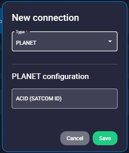
Planet connection configuration
Satcom ID must be set.
Finally, click on Save.
Note
In case of not getting the device connected, make sure that the PC acquires a communication port.
Sessions
Sessions tab displays all finished device sessions.
Note
Sessions that are currently being recorded will not be displayed.
The following image and list describe each functionality.
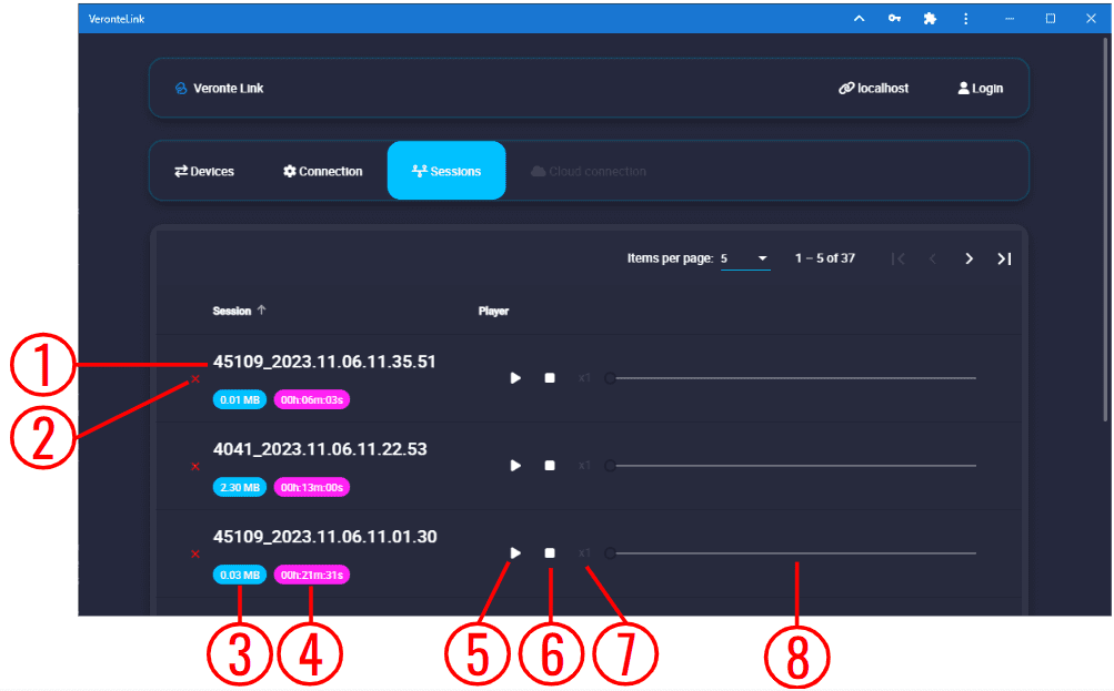
Sessions menu
Session name: It is made with recording time (date and hour).
Delete session. If the user wishes to delete more than 1 session at a time, it is possible to delete them from the Veronte Link sessions folder located in the following path:
C:\Users\USER NAME\AppData\Roaming\VeronteLink\sessionsFiles weight.
Duration.
Play/Pause: Play button creates a virtual device similar to the following figure:
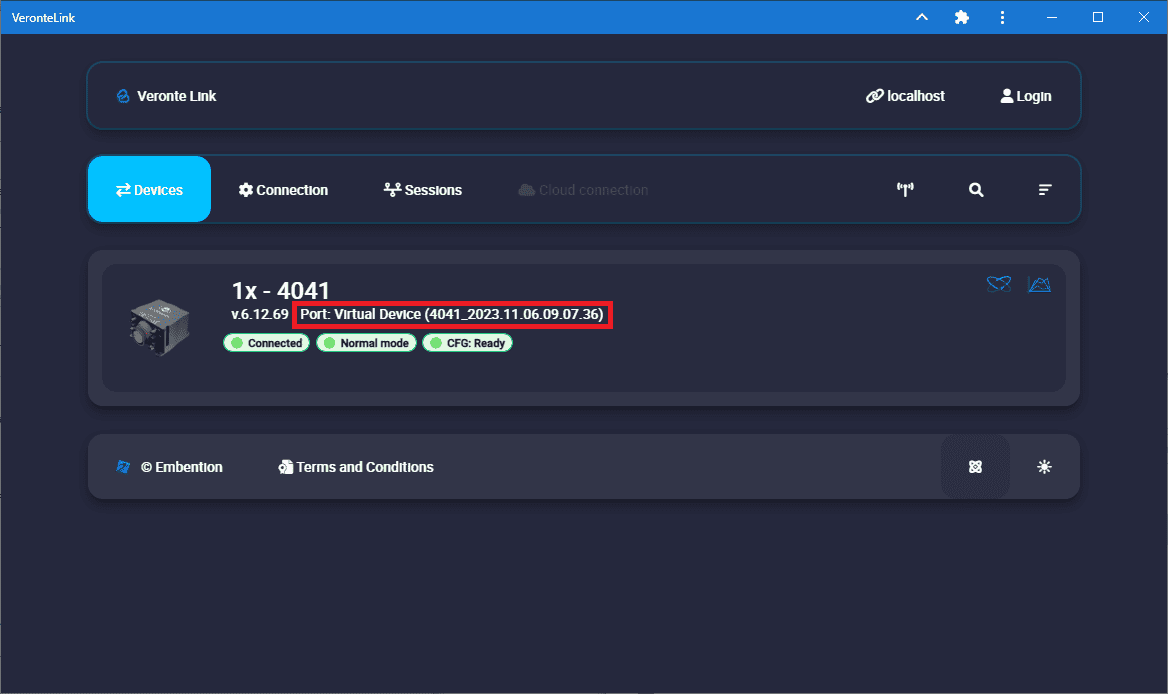
Virtual device
It starts a simulation replaying everything that happened during the session recording. It will recreate all the ocurred events with detail and Veronte Ops will display the corresponding data and trajectories; read the Veronte Ops user manual for more information.
Note
In addition, when the virtual device is in a ready state, users can open the 1x PDI Builder software and download the configuration (PDI files).
Stop: It stops playing the session. It does not delete the session.
Speed: Playing speed can be selected as x0.5, x1, x2, x4 and x8.
Display bar: Click and drag to replay any moment.

Cloud connection
Cloud connection tab allows the user to connect to a Veronte Autopilot 1x through LTE network. This functionality is enabled thanks to the HSPA+ module (internal or external) embedded in Veronte autopilots.
Note
To activate the internal card or Veronte Cloud data traffic through internet, please contact sales@embention.com. Remember that there is no internet connection when HSPA+ module is deactivated.
To configure this type of connection, these steps must be followed:
Login: After clicking the Login button, users must introduce their associated username and password.
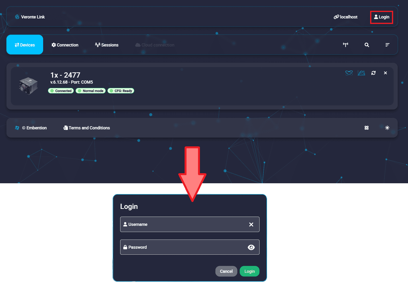
Cloud Connection: Login
Note
Login credentials are automatically assigned. In case they have not been provided to you, please contact the support team by creating a ticket in the customer’s Joint Collaboration Framework; for more information, see Tickets section of the JCF manual or contact sales@embention.com.
Open Cloud connection tab. Veronte Autopilots 1x linked to user’s account should be displayed.
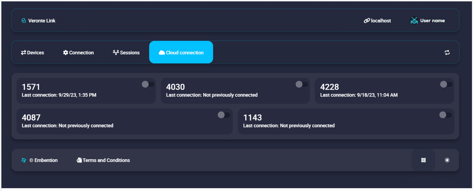
Cloud Connection: Available devices
The following information is displayed for each autopilot:
ID: Identification number of the autopilot (Serial Number).
Last connection: Indicates the date on which the last connection to that device was established.
Activate the connection with the desired Autopilot 1x by turning on the toggle button displayed next to it.

Cloud Connection: Connect to an Autopilot 1x
Note
Since Cloud connections are based on LTE communication, this connection may not be immediate. The selected autopilot will only be displayed in the ‘Devices’ tab when it is succesfully connected.
At this point, Veronte Link must have established the connection with the selected Autopilot 1x. Consequently, the autopilot must be displayed in the Devices tab.
Note
Since Cloud connections are based on LTE communication, connection may be lost even when the toggle button is on. In this case, the autopilot will disappear from the ‘Devices’ tab, appearing again when the connection is retrieved.
Log out: Click on the username to enable the log out button, and then press it.
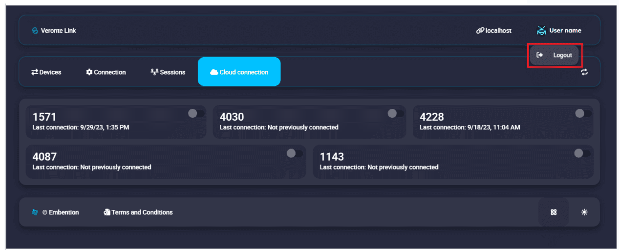
Cloud Connection: Log out