Magnetometer
The magnetometer inputs expect to receive magnetic field measurements in 3 axes, as well as the sensor device temperature.
The S-Function has 4 ports for magnetometer reading. In addition, as with IMUs, the user must take into account how the magnetometer is mounted (rotation matrix).
Hardware version |
S-Function Input |
Rotation Matrix |
1x PDI Builder equivalence |
|
|---|---|---|---|---|
PIN |
Description |
|||
4.0 |
8 |
Magnetometer 1 |
\(R =\begin{pmatrix} -1 & 0 & 0 \\ 0 & 1 & 0 \\ 0 & 0 & -1 \end{pmatrix}\) |
0 - Internal 0 |
4.5 |
8 |
Magnetometer 1 |
\(R =\begin{pmatrix} -1 & 0 & 0 \\ 0 & 1 & 0 \\ 0 & 0 & -1 \end{pmatrix}\) |
0 - Internal 0 |
9 |
Magnetometer 2 |
\(R =\begin{pmatrix} 0 & -1 & 0 \\ -1 & 0 & 0 \\ 0 & 0 & 1 \end{pmatrix}\) |
1 - Internal 1 |
|
4.8 |
8 |
Magnetometer 1 |
\(R =\begin{pmatrix} 0 & 0 & -1 \\ 0 & 1 & 0 \\ 1 & 0 & 0 \end{pmatrix}\) |
0 - Internal 0 |
9 |
Magnetometer 2 |
\(R =\begin{pmatrix} 0 & 0 & 1 \\ -1 & 0 & 0 \\ 0 & 1 & 0 \end{pmatrix}\) |
1 - Internal 1 |
|
10 |
Magnetometer 3 |
\(R =\begin{pmatrix} 0 & 0 & 1 \\ 1 & 0 & 0 \\ 0 & 1 & 0 \end{pmatrix}\) |
2 - Internal 2 |
|
Note
There may be inputs (ports) not connected since the S-Function contains the maximum number of possible inputs for the different hardware and SIL Simulator versions, as can be seen in the aforementioned table.
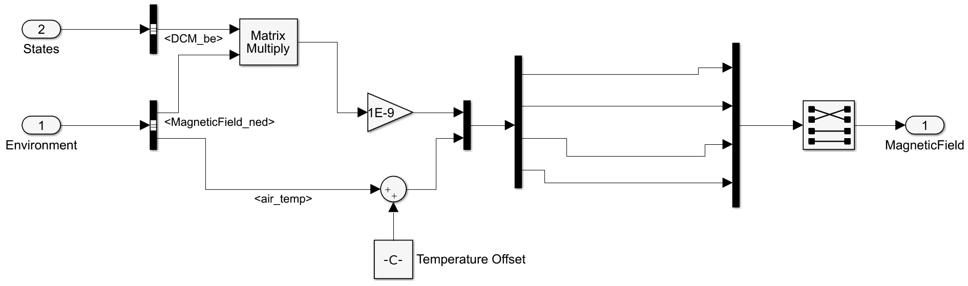
Magnetometer - Subsystem
The user can also simulate another magnetometer (external magnetometer) and send the information through a serial port. For more information on serial communication, refer to Serial communications section of this manual.