Hardware Installation
Version |
Fixation |
|---|---|
MEX |
2x M3 screws |
MEX OEM |
4x M2 screws (2 of them must not be ferrous) |
Note
To install MEX in a vehicle, female and male electrical connectors can be secured with glue to prevent disconnections, such as epoxy or Methyl methacrylate.
Pinout
Pins are arranged as follows:
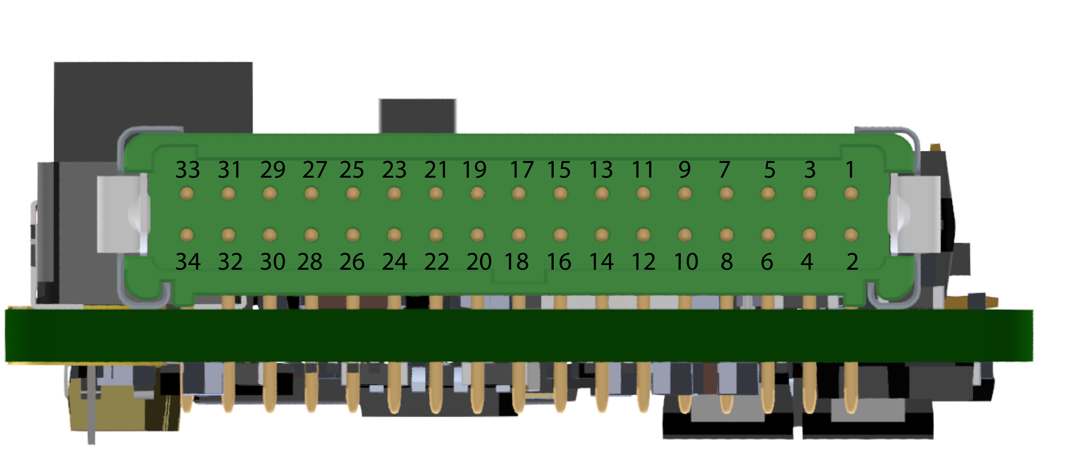
PIN Nº |
I/O |
Comments |
|---|---|---|
1 |
Power supply 1 |
Power supply for the main system, redundant with Power supply 2 |
2 |
GND |
Ground for supply |
3 |
Power supply 2 |
Power supply for the main system, redundant with Power supply 1 |
4 |
GND |
Ground for supply |
5 |
SCL |
I2C CLOCK |
6 |
SDA |
I2C DATA |
7 |
ANALOG (1) 5V |
Analog input 0-5 V |
8 |
ANALOG (2) 5V |
|
9 |
ANALOG (3) 12V |
Analog input 0-12 V |
10 |
ANALOG (4) 36V |
Analog input 0-36 V |
11 |
GND |
Ground for supply |
12 |
ECAP 1 |
ECAP, EQEP or GPIO (only as input) |
13 |
ECAP 2 |
|
14 |
GND |
Ground for supply |
15 |
RS-232 (A) TX |
RS-232 A Output |
16 |
RS-232 (A) RX |
RS-232 A Input |
17 |
GND |
Ground for supply |
18 |
RS-232 (B) TX |
RS-232 B Output |
19 |
RS-232 (B) RX |
RS-232 B Input |
20 |
CAN B (P) |
CAN bus interface. It supports data rates up to 1 Mbps |
21 |
CAN B (N) |
|
22 |
CAN A (P) |
|
23 |
CAN A (N) |
|
24 |
CAN GND |
Isolated ground for CAN bus |
25 |
PWM 1 |
PWM/DIGITAL output /DIGITAL input signal (0-5V) |
26 |
PWM 2 |
|
27 |
PWM 3 |
|
28 |
PWM 4 |
|
29 |
GND |
Ground for supply |
30 |
OUT RS-485 (P) |
Non-inverted output from RS-485 bus |
31 |
IN RS-485 (N) |
Inverted input to RS-485 bus |
32 |
OUT RS-485 (N) |
Inverted output from RS-485 bus |
33 |
IN RS-485 (P) |
Non-inverted input to RS-485 bus |
34 |
RS-485 GND |
Ground for RS-485 |
Warning
Each CAN bus is equipped with a 120 Ohm (+/-5%) termination resistor that can be activated and deactivated by SW.
Warning
RS-485 has internal termination resistor with 120 ohms (+/-5%).
Warning
I2C is equiped with internal pull-up resistors.
Note
Pins 1 and 3 are not common.
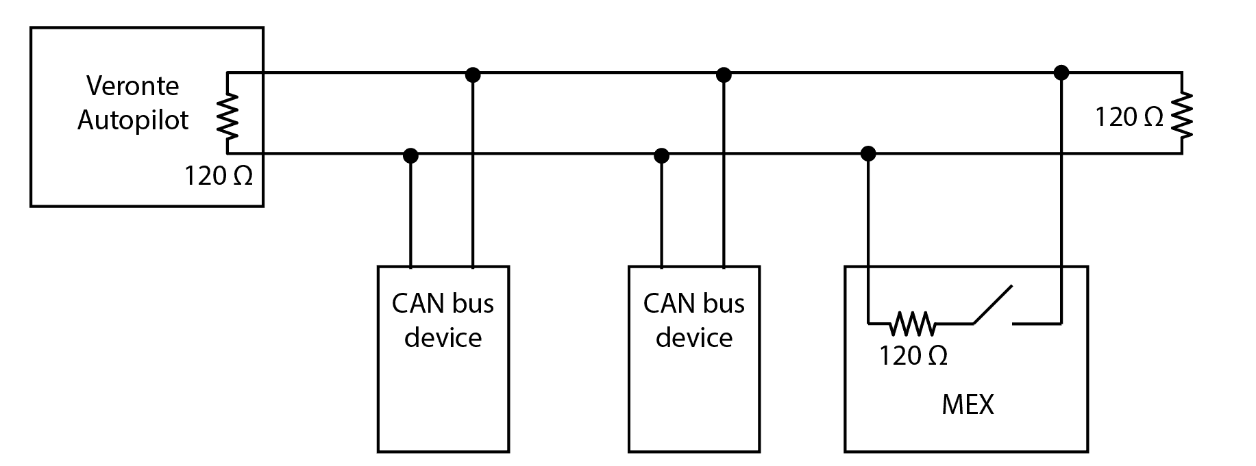
Electrical diagram of CAN bus
Veronte MEX requires termination resistance in order to allow the connection of multiple Veronte MEX or other CAN Bus devices to the same line. Considering Veronte Autopilot includes one entrance resistance of 120 Ω, a second resistance needs to be placed at the end of the line (again 120 Ω). This resistance may be placed on the cable or on another PCB.
CAN assembly diagram example
Veronte MEX has an internal resistor of 120 Ω, which can be activated by SW. Then, another way to connect multiple CAN Bus devices lies in connecting a MEX to the end of cables, then activating its internal CAN resistor.
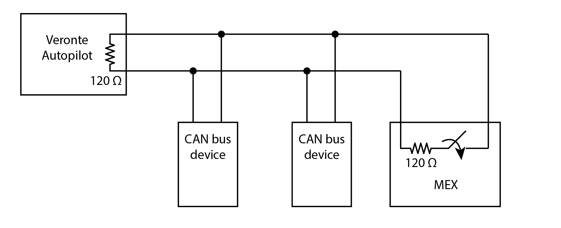
Diagram with CAN resistor activated