MC
Open Loop Startup
If it is not possible to start-up with the low speed PLL observer, it could be done by the open loop procedure:
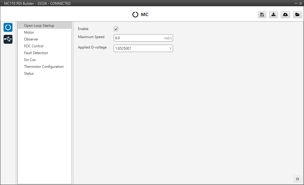
The user can configure the following parameters:
- Enable: Enables the open-loop start-up procedure. This could be used to perform some initial testing without a fine tuning.
- Maximum Speed: Maximum speed reached on the start ramp. It is usually approximately 10-15% of the maximum speed of the mechanical motor.
- Applied D-voltage: This field defines the direct-axis voltage that is applied to the motor to generate the initial torque required to start spinning.
Motor
This tab sets all the electrical/mechanical parameters of the motor that will define the controller dynamics, which should be obtained from its official datasheet.
These values are the foundation for the controller's dynamics and are critical for achieving stable and efficient performance.
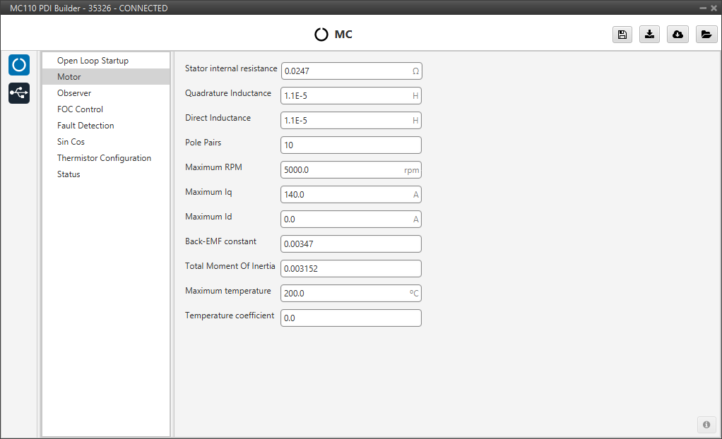
- Stator internal resistance: This is the line-to-neutral resistance of the motor. Here it is necessary to take into account the harness resistance if it is not negligible.
- Quadrature/Direct Inductance: Line-to-neutral motor inductance in q-d axes.
- Pole Pairs: The number of pole pairs shall allow calculation of the mechanical speed of the motor.
- Maximum RPM: Maximum desired mechanical speed that the motor will reach in normal operation. It allows to calculate the input rate in terms of desired speed.
-
Maximum Iq: Maximum permissible quadrature current that the motor can drive. This is directly related with the maximum permissible motor torque.
In a scheme (no MTPA/FW) and steady-state operation, this is the allowed phase current peak value.
-
Maximum Id: Maximum allowable direct current that the motor can conduct. Only used in the MTPA/FW scheme.
- Back-EMF constant: This is the line-to-neutral Back-EMF constant. Usually known as magnetic flux.
- Total Moment Of Inertia (MOI): Total moment of inertia (motor + load). This is only used for speed regulator gain auto-calculation tool.
- Maximum temperature: The maximum operating temperature that the motor can safely withstand. If this temperature is reached, a health alert will be raised.
- Temperature coefficient: The temperature coefficient of the stator resistance. If the appropriate thermistor is configured, this value allows the controller to compensate for changes in motor resistance as it heats up, improving control accuracy.
Note
Back-EMF constant is an important parameter for low-speed PLL observer, so a correct characterization of this parameter will allow control in the low-speed range and start-up without open-loop procedure.
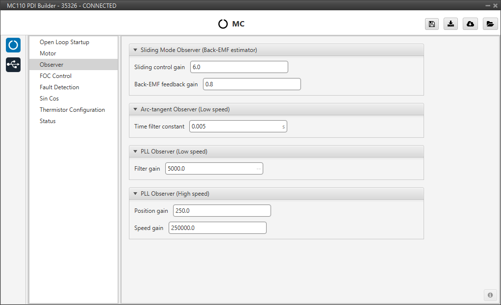
Observer
The algorithm is prepared to work with two observers (low and high speed observer) working in a predefined speed range.
Moreover, there are two low-speed observers that can be selected: PLL observer and Arc-tangent observer (this should be configured in the FOC Control panel). The first one allows starting without open loop while the second is usually selected when there is an open loop procedure.
The observer mixing limits [low,up] are usually approximately 2% and 15% of the maximum mechanical speed.
Warning
No changes are expected in this menu from the default values.
Here the observers parameters must be configured:
-
Sliding Mode Observer (Back-EMF estimator): Sensor-less estimator for the Back-EMF.
- Sliding Control Gain: This is the main gain of the observer. To ensure the stability of the algorithm, this value must be greater than the absolute value of Back-EMF on the alpha/beta axes.
- Back-EMF feedback gain: This value is to account for unfiltered Back-EMF. It should be between 0 and 1.
-
Arc-tangent Observer (Low speed): It is one of the low speed position observers.
- Time filter constant: This is the time constant of the first order filter of the speed calculation. The lower value, the lower filtering.
-
PLL Observer (Low speed): It is the second one low speed position observer.
- Filter gain: Filter cutoff frequency.
Note
Users can choose one of the two low-speed observers (arc-tangent or PLL) by selecting it in the Low speed observer parameter of the FOC control menu.
-
PLL Observer (High speed): This is the high speed position observer. It is controlled by a PI control.
-
Position gain: This is the proportional gain for the position estimation loop. It determines how aggressively the observer corrects errors in the estimated rotor angle. A higher value results in a faster response, but may lead to instability if set too high.
-
Speed gain: This is the integral gain for the speed estimation loop. It works with the Position gain to eliminate steady-state errors and dampen oscillations, ensuring a stable lock on the motor's speed.
-
Warning
It is recommended to tune this estimator even if an external sensor is used for feedback (sensored control).
As it will be described in the next section, the control will automatically jump in case the primary feedback source fails to a sensorless control.
FOC Control
First, the PI (Proportional and Integral) controller is presented.
The form of the PI is the classical parallel form:
Where integral gain refers to the quotient . Lower and upper saturation gain are the limits to which the PI limit its output.
FOC Control is the main control menu, where all parameters related to FOC control are set.
The basic blocks that define the FOC control are three PI control loops that should be tuned with the motor characterization.
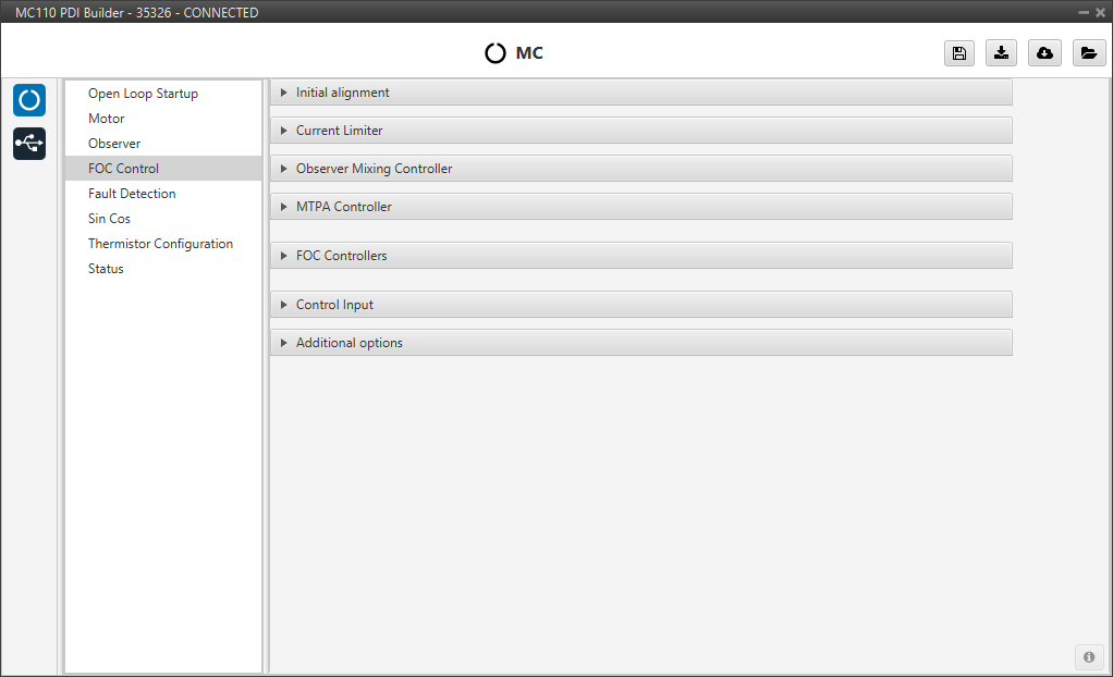
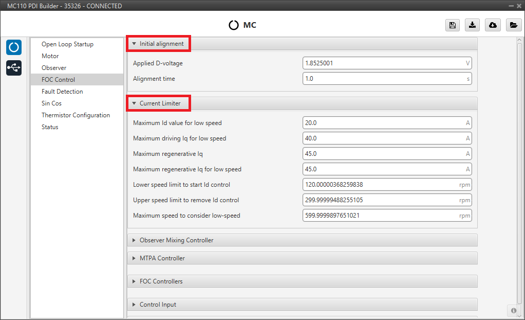
Initial alignment
Note
These default parameters should work correctly.
Start-up initial alignment procedure in order to fix the motor starts from a known position. This is used by the Sin/Cos sensor to calibrate the sensor.
This procedure allows the rotor to always be aligned in the same electrical position.
Note
This part of the configuration is essential if the Sin/Cos sensor is enabled.
- Applied D-voltage: This sets the desired direct-axis voltage used to align the rotor.
- Alignment time: time used to set previous voltage. Usually about 1 second.
Current Limiter
Warning
Only changes regarding speed are expected in this menu from the default values. This is specially important in a sensor-less very low speed operation.
Limiter block for the desired currents and .
- Maximum Id value for low speed: maximum allowed D-current when the speed is lower than Lower speed limit to start Id control.
- Maximum driving Iq for low speed: maximum driving Q-current when speed is lower than Maximum speed to consider low-speed.
- Maximum regenerative Iq: maximum allowable regenerative Q-current when a break/reverse operation is required.
- Maximum regenerative Iq for low speed: maximum breaking Q-current when speed is lower than Maximum speed to consider low-speed.
- Lower speed limit to start Id control: lower speed limit to consider adding Id control with a value of Maximum Id value for low speed. This about a 2% maximum motor speed.
- Upper speed limit to remove Id control: upper speed limit to consider adding Id control with a value of Maximum Id value for low speed. This about a 6% maximum motor speed.
- Maximum speed to consider low-speed: low speed limit to consider Iq limiting using limits defined at Maximum regenerative Iq for low speed and Maximum driving Iq for low speed.
Observer Mixing Controller
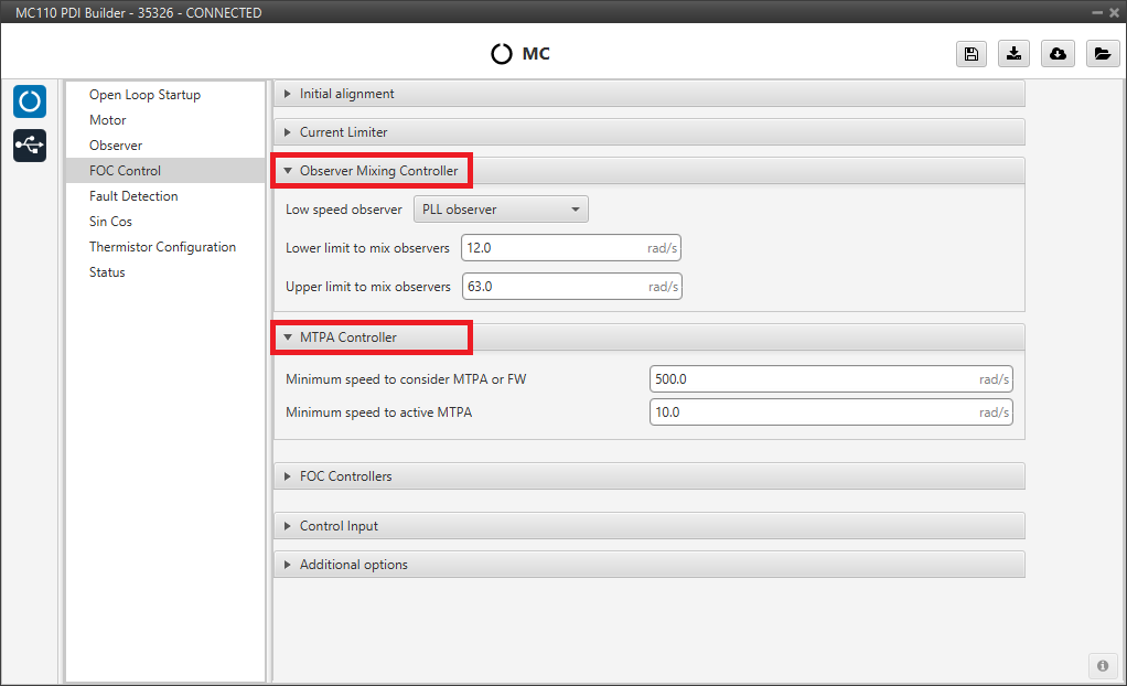
Definition of the range of low-high speed observers.
- Low speed observer: Users should select the low-speed observer to be used: arc-tangent or PLL.
- Lower limit to mix observers.
- Upper limit to mix observers.
MTPA Controller
Maximum Torque Per Ampere controller. It is used to reach a higher speed than the base speed of the motor. In addition, it can work in a Field Weakening to control with .
- Minimum speed to consider MTPA or FW.
- Minimum speed to active MTPA.
FOC Controllers
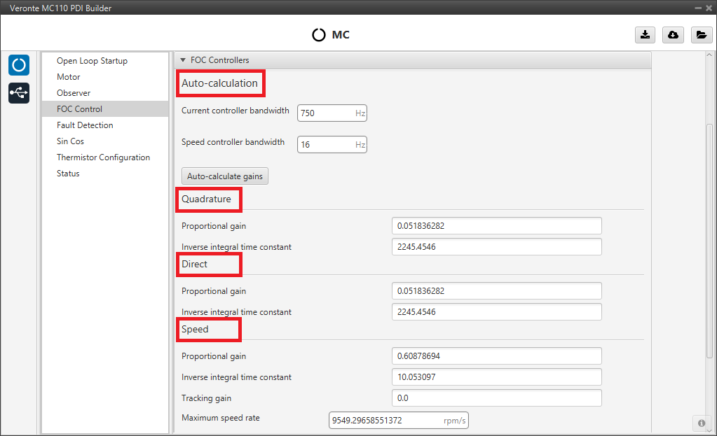
This section is used to define the three main PI control loops of the FOC algorithm: the Quadrature current (torque regulator), Direct current (flux regulator), and motor Speed Controller.
-
Auto-calculation: Instead of calculating gains manually, the user can input the desired performance characteristics, and the system will compute the appropriate gains considering the motor characteristics and the desired bandwidth.
- Current controller bandwidth: Defines the desired responsiveness of the current control loops (Direct and Quadrature).
- Speed controller bandwidth: Defines the desired responsiveness of the speed control loop.
- Auto-calculate gains button: After setting the desired bandwidths, the user clicks this button to automatically fill in the gains fields below.
Note
The Quadrature and Direct PI gain settings are usually the same, but it will depend on whether the motor parameters are the same on both axes.
Alternatively, the user can enter the gains manually in the sections below. These fields will be fill in automatically when using the auto-calculation feature. The gains are divided into three sections:
- Quadrature Controller: This loop controls the quadrature current , which is directly related to the motor torque. It is controlled by a PI control.
- Direct Controller: This loop controls the direct current , which is related to the magnetic flux of the motor. It is controlled by a PI control.
-
Speed: This loop controls the rotational speed of the motor. It is controlled by a PI control. In addition to the Proportional gain and Inverse integral time constant, the user can also set:
- Tracking gain: An additional gain to improve the controller's ability to track the desired speed reference and avoid controller wind-up.
- Maximum speed rate: Defines the maximum desired acceleration that the motor will perform. This is platform dynamics dependent.
Control Input
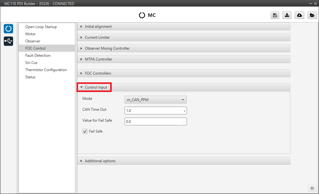
Control input allows the user to select the input source and several additional parameters such as:
- Mode: Control mode. The available options are m_PPM, m_CAN and m_CAN_PPM.
-
CAN Time Out: Whenever this timeout is met, the control input will switch to the next option if available. If none of them are available, it shall end up in failsafe mode. A health alert will any of the sources are not available.
-
Value for Fail Safe: Value between 0 and 1. To be written in case the previous mode options are not available.
- Fail Safe: Activates failsafe mode.
The input flow is the following in case the mode m_CAN_PPM is selected:

Additional options
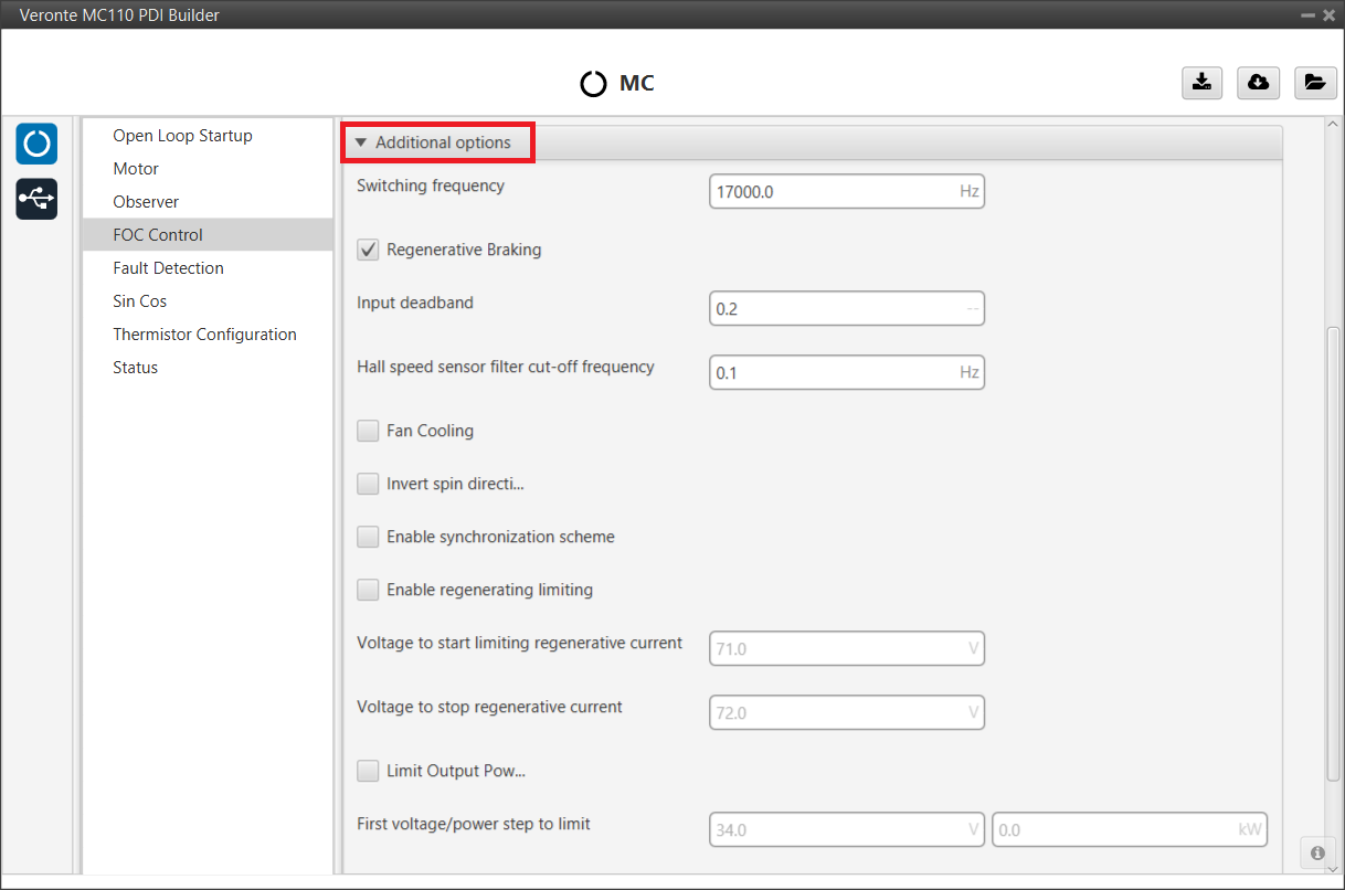
In this section, a variety of advanced features and behaviors of the motor controller can be configured.
The available parameters are:
- Switching frequency: Defines the switching frequency of the controller's transistors. Higher values can result in smoother motor operation but may increase thermal losses.
-
Regenerative Braking: Activates regnerative braking feature which is basically consisting of thoughing negative current back to battery whenever the motor is loosing speed (it uses the kinetic energy to charge de battery). If disabled, it will only allow slow down due to losses.
Warning
Activating this option is only recommended with batteries (charging them when braking), but not with a power supply, as they are not prepared to receive current (it is necessary to activate the sink mode to work with it).
-
Input deadband: This is the value of the input rate at which the motor will start to move. For example, it may be desired to be non-zero in case an RC stick outputs about 0.2 duty cycle by default.
Note
In case CAN Bus is used to command (see CAN I/O - Input/Output section of this manual), this deadband can be calculated as .
-
Hall speed sensor filter cut-off frequency: Configures the cut-off frequency for the speed signal filter when using Hall sensors, which helps to smooth the speed reading.
- Fan Cooling: This option activates a PID control on a cooling fan to reach normal operating temperature.
- Invert spin direction: Reverses the motor's direction of rotation without needing to change the phase wiring.
-
Enable regenerating limiting: Activates a system to limit the regenerative current, which is useful for protecting the battery from overvoltage during intense braking. The following parameters are available when enabled:
- Voltage to start limiting regenerative current: The battery voltage at which the system begins to limit the regenerative current.
- Voltage to stop regenerative current: The battery voltage at which the system stops limiting regeneration.
-
Limit Output Power: Activates a system to limit the maximum output power of the motor, based on the battery voltage. When enabled, a multi-step power limit curve can be configured:
- First/Second/Third voltage/power step to limit: These fields allow the user to define a stepped power limit. As the battery voltage is between certain ranges (first field), the maximum output power is reduced to the specified value in the second field.
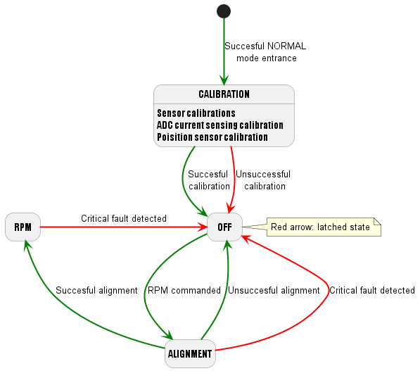
Finally, the following state machine will be executed during a normal operation (when the open loop procedure is disabled):
Fault Detection
This tab allows the user to configure the thresholds for various electrical and system faults, as well as identify whether faults are critical or not.
Values definition
This section is used to set the specific numerical limits and timings that will trigger a fault condition. The parameters whose limits can be modified by the user are:
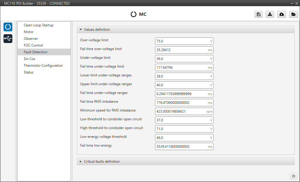
Types of fault detection:
- Over-voltage: Over-voltage detected in battery.
- Under-voltage: Under-voltage detected in battery.
- RMS imbalance: Imbalance detected between phase currents.
- Open-DC: Potential open circuit detected in battery.
- Low-energy: Low voltage battery detected during a long time.
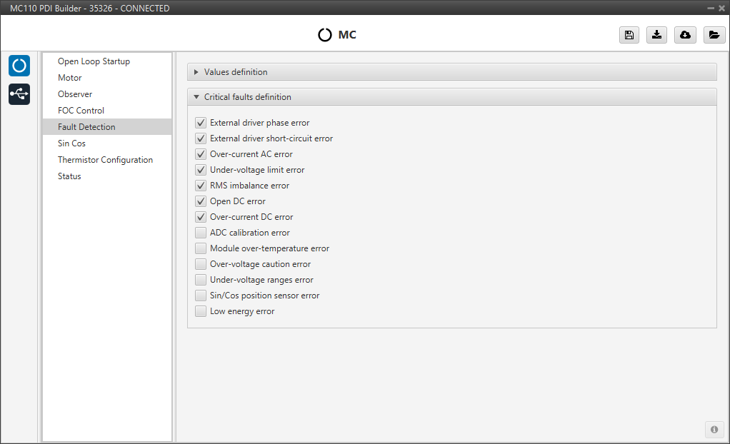
Critical faults definition
Users can mark which faults should be considered critical. The differences between critical and non-critical:
- Critical fault: It will be followed by a latched OFF state.
- Non Critical fault: It will be only followed by a warning.
Warning
Although it is possible to change critical faults to non-critical and vice versa, it is not recommended to modify the default settings. For this reason, the following warning message appears when entering this panel:

Sin Cos
In case it is necessary to use an external SIN/COS sensor as a source of electrical angle/speed feedback, the main interface for doing so is via ADC inputs.
This menu allows users to calibrate their sensor. Proper calibration corrects analog signal errors, ensuring accurate angle feedback for the motor controller.
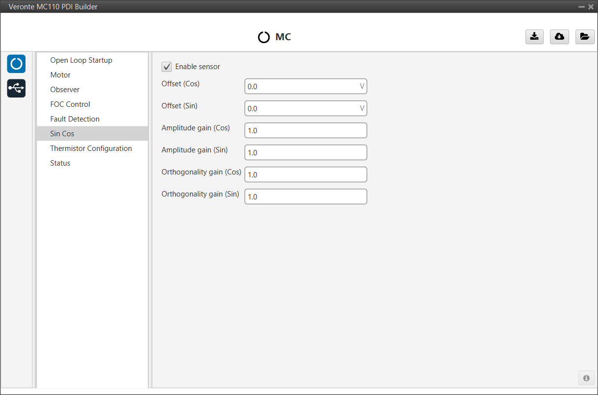
The parameters that can be configured by the user are:
- Enable sensor: Checkbox to activate or deactivate the external Sin/Cos sensor for feedback.
- Offset (Cos) / (Sin): Corrects DC voltage offsets to center the Cosine and Sine signals at 0V.
- Amplitude gain (Cos) / (Sin): A multiplier that scales the signal to ensure both Sine and Cosine have identical amplitudes, which is critical for precise angle calculation.
- Orthogonality gain (Cos) / (Sin): Corrects phase errors. This gain ensures the Sine and Cosine signals are perfectly orthogonal (90 degrees apart).
Note
If the calibration values are not known, this is auto-calculated by the system enabling open-loop procedure and initial alignment.
Thermistor Configuration
This section is for configuring a thermistor to provide accurate temperature readings.
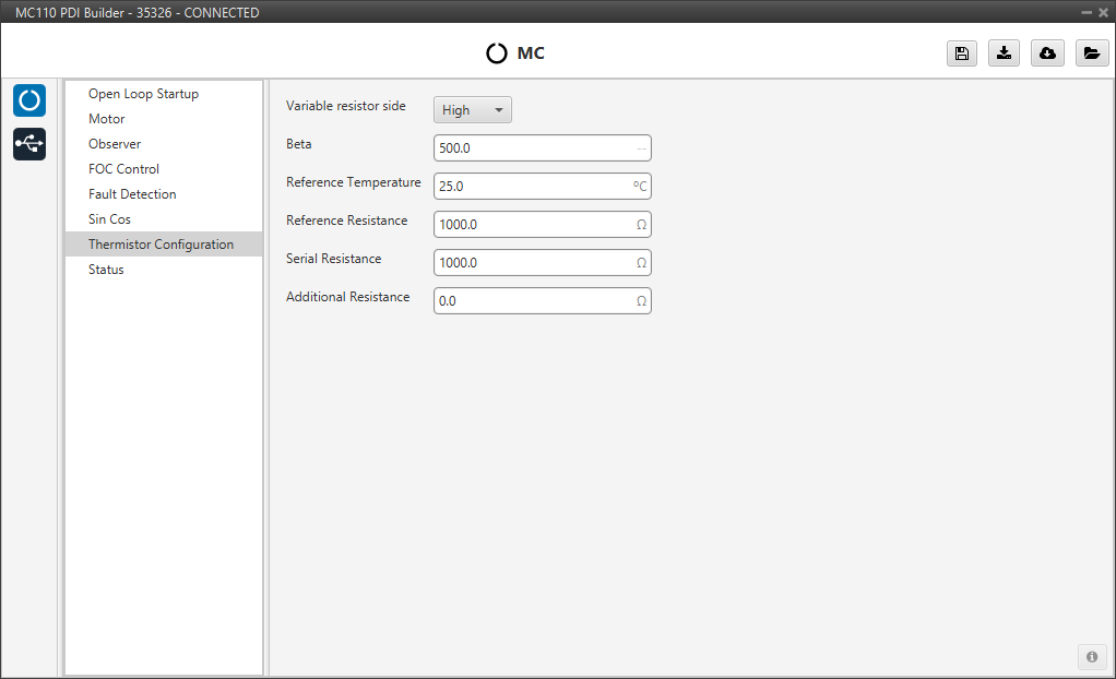
Set the following parameters:
- Variable resistor side: Sets the thermistor's position in the voltage divider circuit, either High or Low side.
- Beta: The thermistor's Beta coefficient (B-value) from its datasheet.
- Reference Temperature: The temperature for the specified nominal resistance (usually 25°C).
- Reference Resistance: The thermistor's nominal resistance at the reference temperature.
- Serial Resistance: The value of the fixed resistor in the voltage divider.
- Additional Resistance: Any extra circuit resistance, such as from wires, to include in calculations.
The variable resistor is calculed using the following equation:
-
For resistor in high side:
-
For resistor in low side:
Where,
- : Reference Resistance parameter
- : Beta parameter
- : Reference Temperature parameter
- : Serial Resistance parameter
- : Additional Resistance parameter
Status
- Enable VCP Status Message enables the periodic sending of the status message that Veronte Link uses to recognise the Veronte Motor Controller MC110.
- Period: Enter a desired period to send repeatedly the status message.
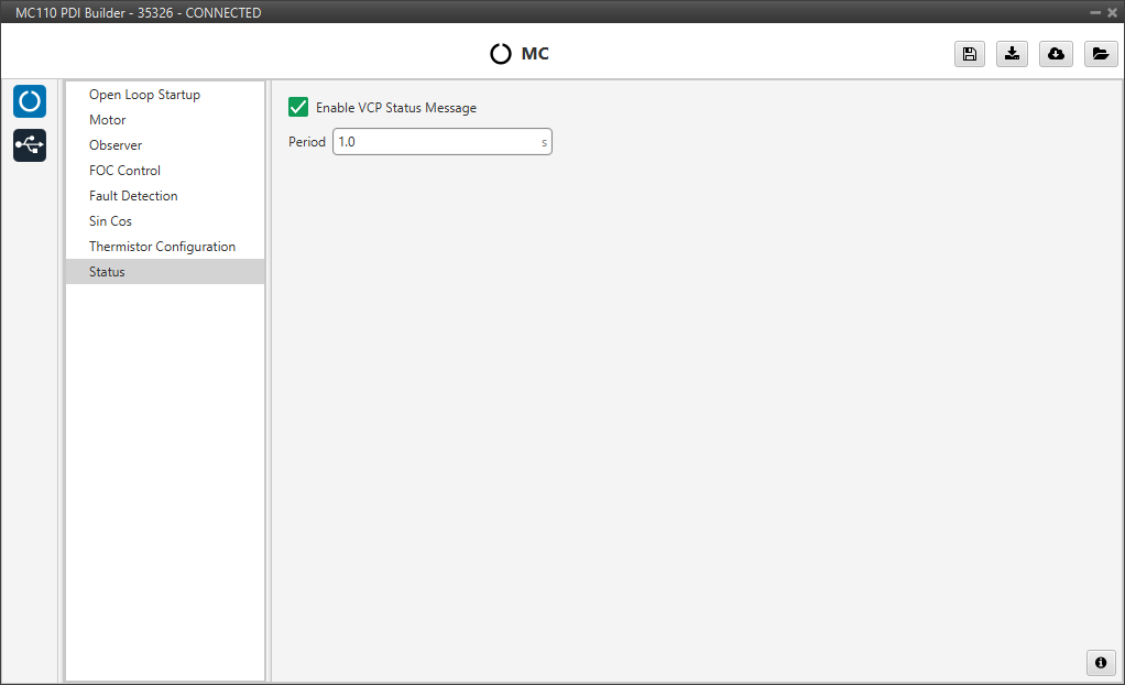
Note
VCP is the Veronte Communication Protocol. To know more, read the VCP user manual.
© 2025 Embention. All rights reserved.