 Control
Control Stepper
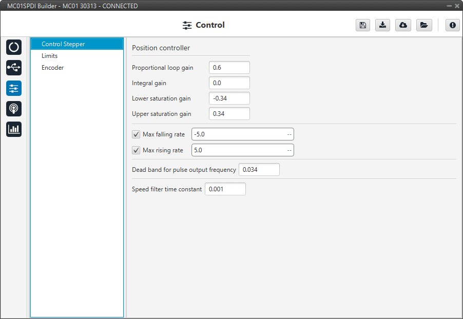
First, the PI (Proportional and Integral) controller is presented.
The form of the PI is the classical parallel form (expressed with Laplace notation):
Where:
\(K_p\) is the Proportional loop gain.
Integral gain refers to the quotient \(\Large \frac{1}{T_i}\).
Lower and Upper saturation gain are the limits to which the PI limit its output.
Control Stepper is the main control menu, where users must enter the control parameters according to their motor.
The basic block that define the control is PI control loop that should be tuned with the motor characterization.

Control Stepper section
Position controller: It is controlled by a PI control.
Maximum desired motor acceleration:
Max falling rate: Deceleration rate. Expressed in \(rad/s^{2}\).
Max rising rate: Acceleration rate. Expressed in \(rad/s^{2}\).
Dead band for pulse output frequency: This is a calibration value.
Speed filter time constant: This is the time constant of the first order filter of the speed calculation. The lower value, the lower filtering.
The time constant is approximately defined as:
\[\tau = \frac{1}{2 \; \pi \; f_{c}}\]Where:
\(\tau\): time constant
\(f_{c}\) : cutoff frequency
Limits
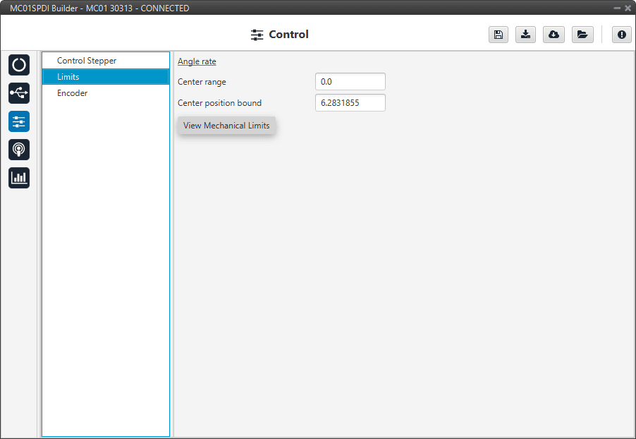
This section allows the user to limit the motor movement by software:

Limits section
Angle rate
Center range: Encoder position at the center of the motor range
Center position bound: Encoder position center of motor’s mechanical limits.
View Mechanical Limits: This panel uses mechanical calibration settings to transform between encoder and mechanical angles.
So, please, edit only if mechanical angle calibration settings are correct.
Encoder
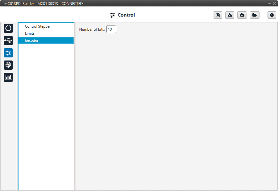
In this section, the user must define the number of bits employed by the encoder to communicate the position of the motor.

Encoder section
