Veronte products
CAN communication
CEX can send telemetry via CAN.
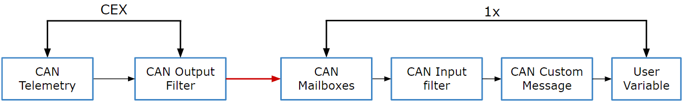
Communication diagram 1x-CEX
The user must follow the steps below to learn how to enable this function and also how to configure an Autopilot 1x to read this telemetry:
CEX PDI Builder side
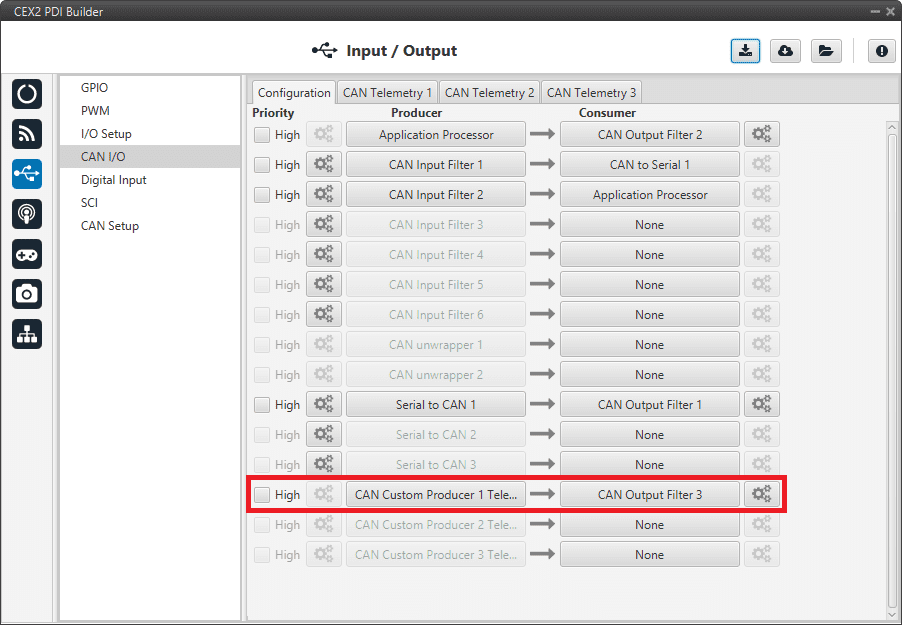
Go to Input/Output menu \(\rightarrow\) CAN I/O panel \(\rightarrow\) Configuration tab.
Connect a CAN Custom Producer Telemetry to a CAN Output Filter as follows:
CAN I/O Custom Telemetry
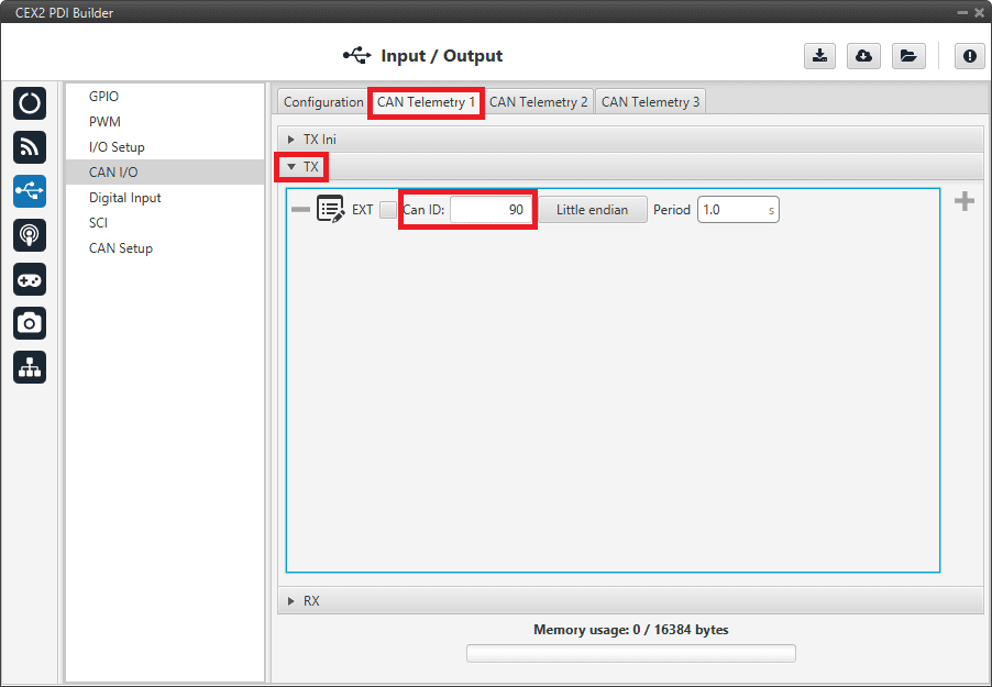
Go to Input/Output menu \(\rightarrow\) CAN I/O panel \(\rightarrow\) CAN Telemetry tab 1 (as the Producer is CAN Custom Producer 1 Telemetry).
Select the fields to send in TX or TX Ini, as it is a Producer. More information on the configuration of Telemetry messages can be found in the CAN Telemetry section.
Note
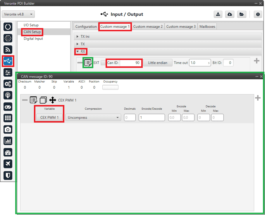
To configure the telemetry received on a CAN Custom Consumer Telemetry, the fields to be read must be configured in RX.
CAN Custom Telemetry
For example, a telemetry messsage with a variable set to ID 90:
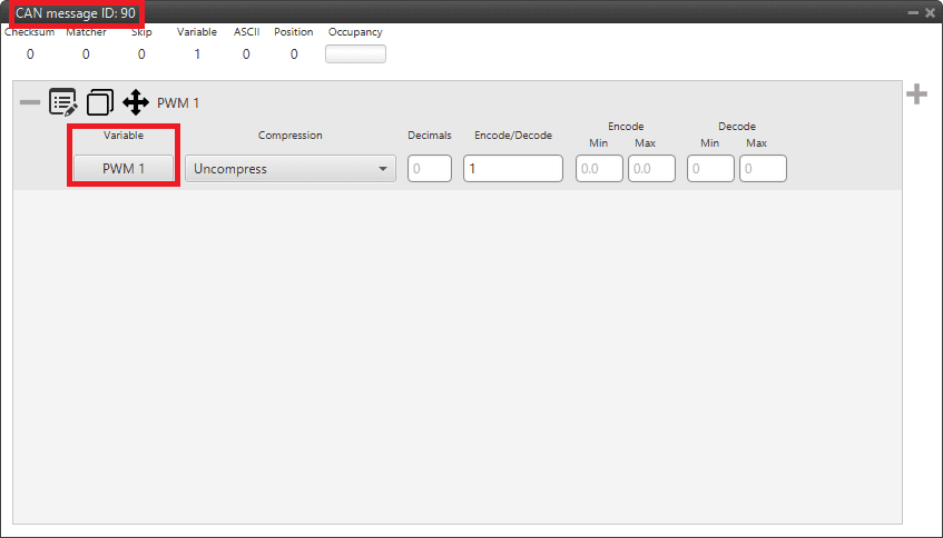
CAN Custom Telemetry example
1x PDI Builder side
Go to UI menu \(\rightarrow\) Variables panel \(\rightarrow\) Real Vars tab.
Rename a User Variable that will be used to store the value received from CEX:
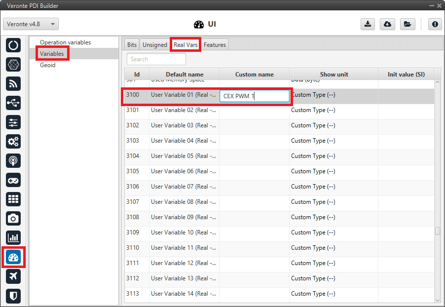
1x PDI Builder - User Variable renamed
Go to Input/Output menu \(\rightarrow\) CAN Setup panel \(\rightarrow\) Mailboxes tab.
Configure the mailbox to receive the message with ID 90 in 1x PDI Builder:
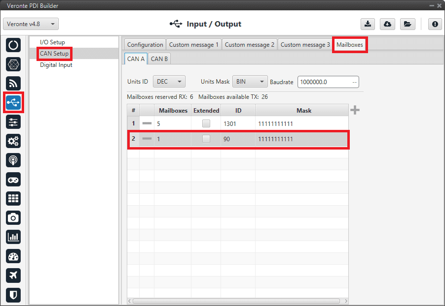
1x PDI Builder - Mailbox configuration
Go to Input/Output menu \(\rightarrow\) CAN Setup panel \(\rightarrow\) Configuration tab.
Connect an Input filter with the right CAN ID to a Custom message consumer:
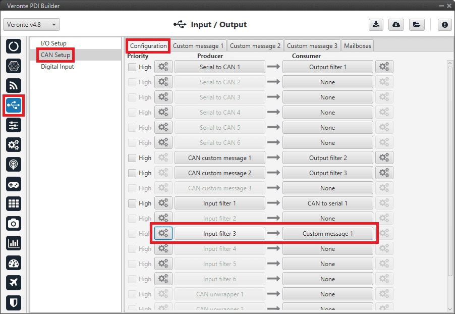
1x PDI Builder - Input filter
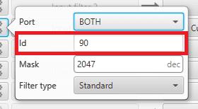
1x PDI Builder - Input filter configuration
Go to Input/Output menu \(\rightarrow\) CAN Setup panel \(\rightarrow\) Custom message 1 tab (as Custom Message 1 has been selected as consumer).
Configure the reading of the message and store the received value in the user variable renamed above:
1x PDI Builder - Custom Message configuration
Commanding/Reading PWMs
The appropriate PWM message format is described in CAN Bus protocol -> Command PWMs of the CEX Software Manuals.
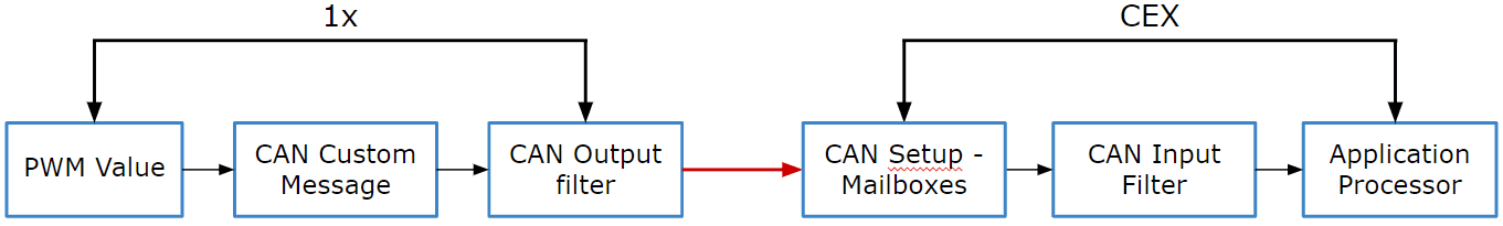
Communication diagram 1x-CEX
The user can follow the following steps to achieve PWM commanding from 1x to CEX:
1x PDI Builder side
Go to Input/Output menu \(\rightarrow\) CAN Setup panel \(\rightarrow\) Configuration tab.
Connect a CAN custom message to an Output filter to send the message:
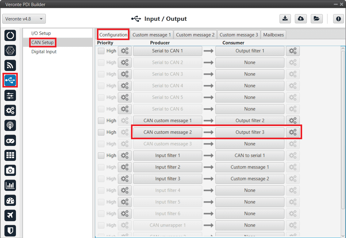
PWM Command - CAN Custom Message
Go to Input/Output menu \(\rightarrow\) CAN Setup panel \(\rightarrow\) Custom Message 2 tab (as Custom Message 2 has been selected as producer).
Build a CAN custom message using the PWM variable and the appropriate Message format. CAN ID is arbitrary, for this example ID 100 will be used:
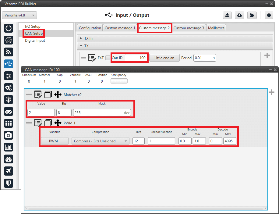
PWM Command - CAN Custom Message configuration
Message format:
Matcher (2) [8 bits]
PWM 1 [12 bits]
PWM 2 [12 bits]
PWM 3 [12 bits]
PWM 4 [12 bits]
Matcher (3) [8 bits]
PWM 5 [12 bits]
PWM 6 [12 bits]
PWM 7 [12 bits]
PWM 8 [12 bits]
Each PWM variable has to be set using the following format:
Variable: PWM X
Compression: Compress - Bits Unsigned
Bits: 12
Encode: Min=0.0 / Max=1.0
Decode: Min=0 / Max=4095
CEX PDI Builder side
Go to Input/Output menu \(\rightarrow\) CAN Setup panel.
Create the mailbox to receive the new message (ID 100):
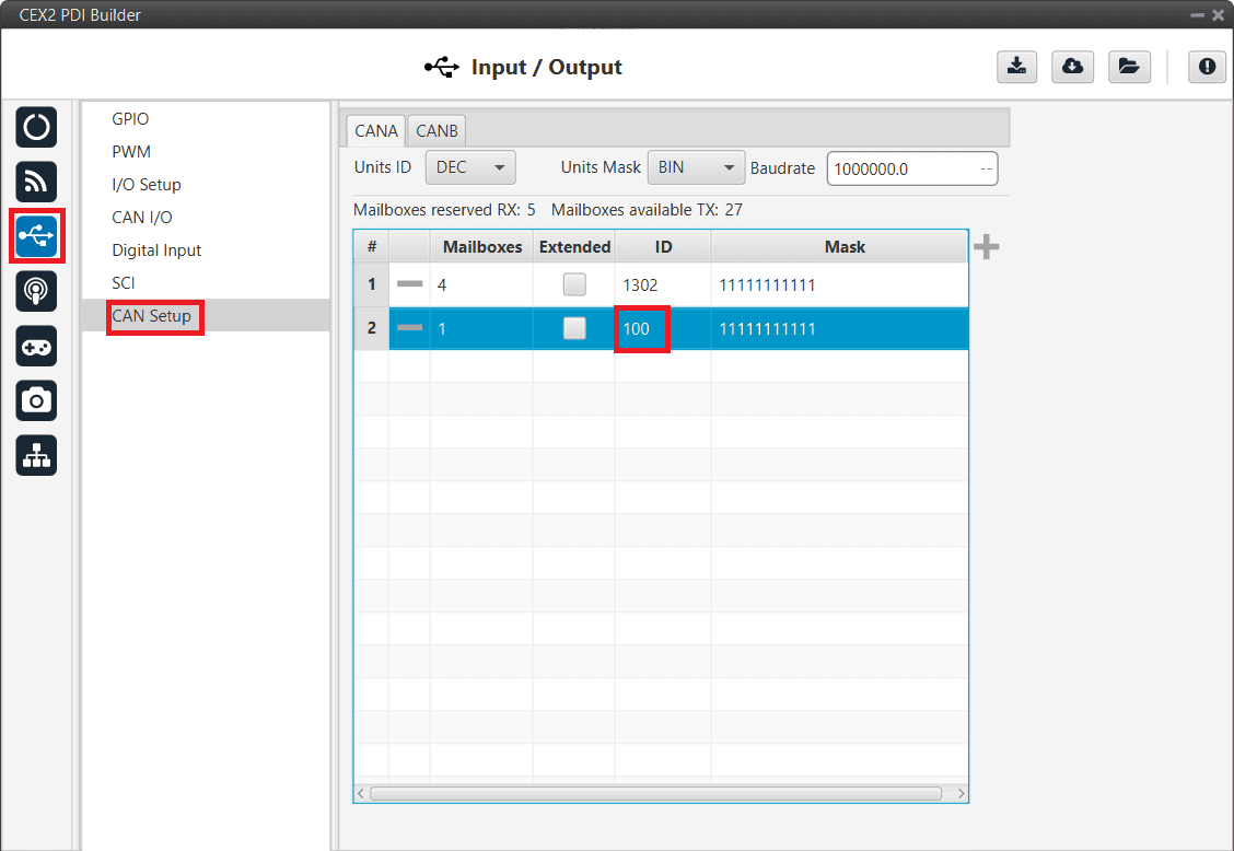
PWM Command- Mailbox configuration
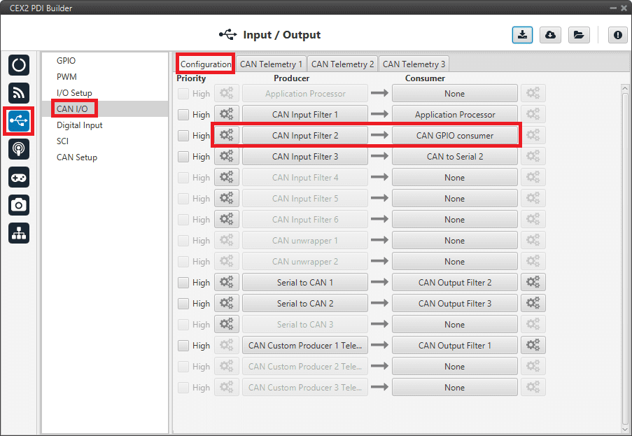
Go to Input/Output menu \(\rightarrow\) CAN I/O panel \(\rightarrow\) Configuration tab.
Connect an Input filter with the right CAN ID to the Application Processor consumer:
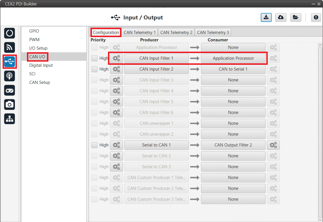
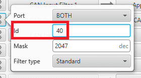
PWM Command - Input filter
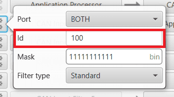
PWM Command - Input filter configuration
Go to Input/Output menu \(\rightarrow\) PWM panel \(\rightarrow\) PWM 1 tab (as PWM 1 has been selected in 1x PDI Builder).
Configure parameters for PWM 1:
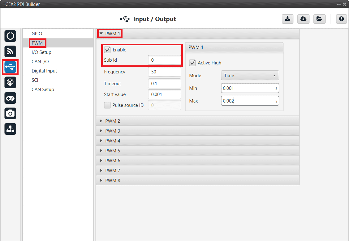
PWM Command - PWM configuration
Finally, export the configuration and save the changes.
Connection with Autopilot 1x via CAN
No configuration is necessary in CEX, the configuration for communication with 1x is set by default.
The configuration required in 1x PDI Builder to communicate with CEX via CAN is explained in the CEX/MEX - Integration Examples section of the 1x PDI Builder user manual.
Connection with Autopilot 4x via CAN
CAN Reception IDs
First, users can setup the recepcion CAN Ids for each of the 3 possible Veronte Autopilots 1x sending data to CEX in the Arbitration menu.
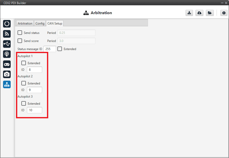
Arbitration - CAN Ids of autopilots
If arbitration is not enabled, and therefore only a 1x autopilot is being used, no CAN Ids need to be configured here.
CAN I/O Interconnections
Once the CAN IDs are set, users shall configure:
The Input Filters going to be used (as communication with CEX has to be always through a Filter).
The connection between input filters and data Consumers.
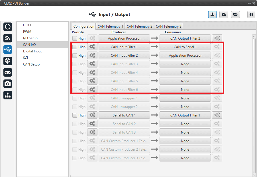
CAN I/O interconnections
For more information on CAN I/O configuration, see section CAN I/O of this manual.
Next step is to connect each of the desired data Producers to an Output Filter, and configure both the Producer and the Output Filter:
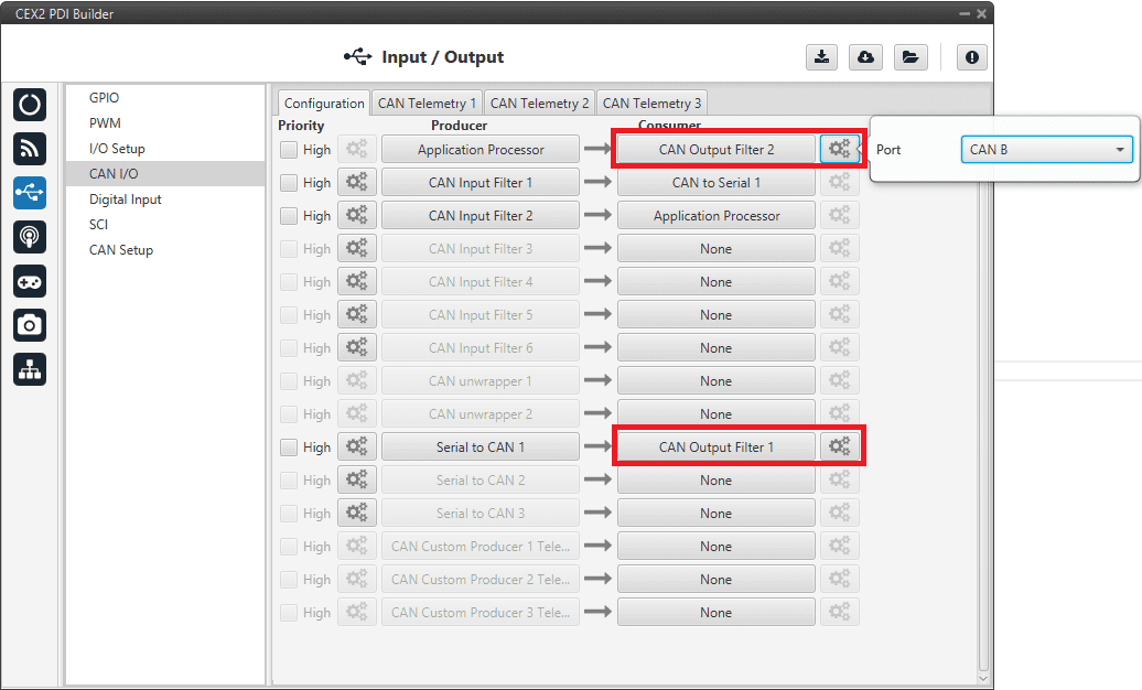
CAN Output Filters
GPIO Command
The following are the steps to send a GPIO command from the Veronte Autopilot 1x, receive it at CEX and process it, so that CEX carries out the command.
Warning
Remember that for the reception of CAN messages, Mailboxes need to be configured accordingly.
GPIO Command is very similar to PWM command with a few exceptions.
1x PDI Builder side
Go to Input/Output menu \(\rightarrow\) CAN Setup panel \(\rightarrow\) Configuration tab.
Connect, as Producer, a ‘CAN GPIO remote’ to an Output filter:
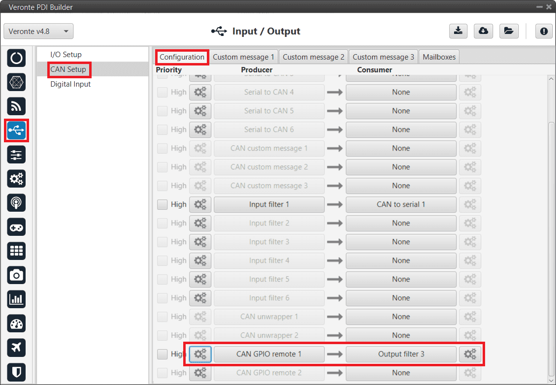
GPIO Command - 1x CAN Setup
CAN GPIO remote must be configured. For more information on its configuration, see 1x PDI Builder manual -> CAN Setup.
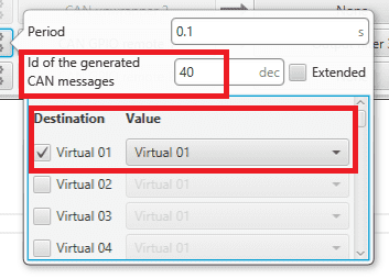
GPIO Command - 1x CAN Setup configuration
Go to Automations menu.
GPIO must be activated using an ‘Output action’:
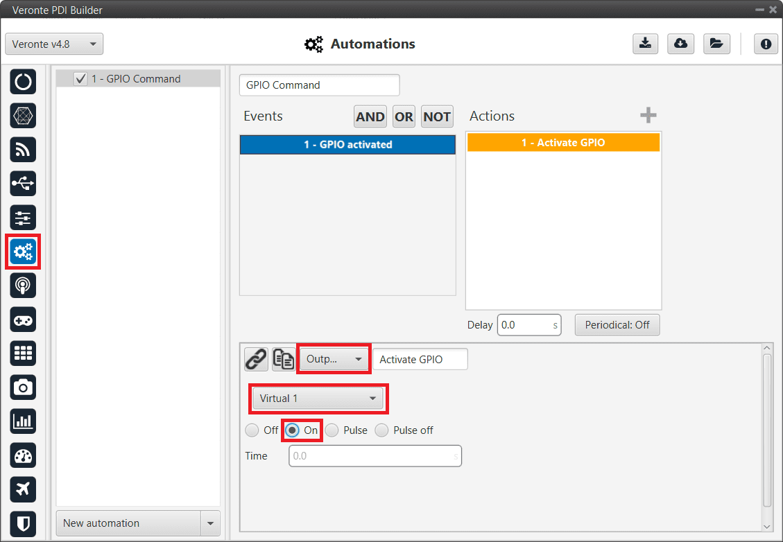
GPIO Command - 1x Automation configuration
CEX PDI Builder side
Reading/Sending RPMs
This section presents the steps to follow to read RPMs.
CEX PDI Builder side
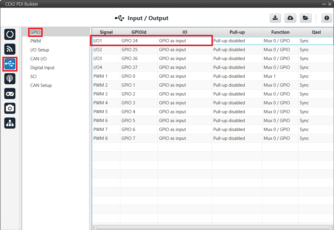
Go to Input/Output menu \(\rightarrow\) GPIO panel.
RPM can be read on the available digital inputs I/O 1-4. The chosen pin needs to be configured as “GPIO as input”. In the example shown here, I/O1 is chosen.
Reading RPMs - GPIO configuration
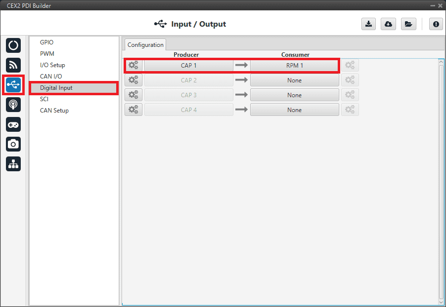
Go to Input/Output menu \(\rightarrow\) Digital Input panel.
There are 4 possible producers: CAP 1-4. One needs to be chosen and linked to one of the RPMs consumers (RPMs 1-4). For more information on Digital input configuration, see section Digital Input of this manual.
Then, select an edge detection option: “First rising edge” or “First falling edge”.
Reading RPMs - Digital Input
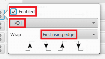
Reading RPMs - Digital Input configuration
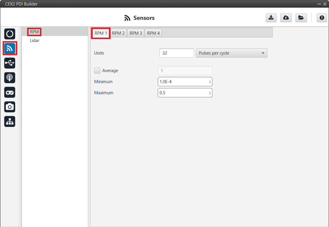
Go to Sensors menu \(\rightarrow\) RPM panel \(\rightarrow\) RPM 1 tab (as RPM 1 has been selected in the Digital Input panel).
Here the expected pulse needs to be defined. For more information on RPM configuration, see section RPM of this manual.
Reading RPMs - RPM configuration
Go to Input/Output menu \(\rightarrow\) CAN I/O panel \(\rightarrow\) Configuration tab.
Connect a CAN Custom Producer Telemetry to a CAN Output Filter as follows (in this example, the RPM1 variable is sent via CAN B bus of the CEX):
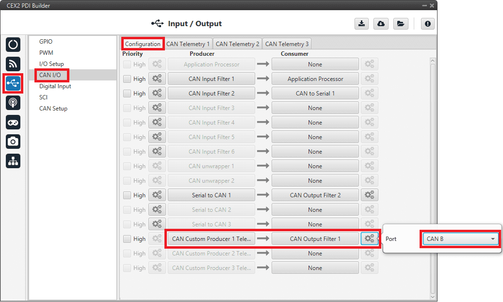
Reading RPMs - CAN Custom Telemetry
Go to Input/Output menu \(\rightarrow\) CAN I/O panel \(\rightarrow\) CAN Telemetry tab 1 (as the Producer is CAN Custom Producer 1 Telemetry).
A new telemetry message needs to be created with its correspondent ID, endianness and period.
Can ID: 1200.
Endianness: Little.
Period: 0.01 s.
In the telemetry message one of CEX’s variables needs to be selected. As RPM 1 has been chosen as consumer in the Digital Input, the variable to be sent is RPM1.
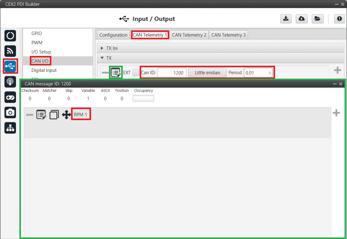
Reading RPMs - CAN Custom Telemetry configuration
More information on the configuration of Telemetry messages can be found in the CAN Telemetry section.
1x PDI Builder side
Go to UI menu \(\rightarrow\) Variables panel \(\rightarrow\) Real Vars tab.
Rename a Real User Variable (32 bits) that will be used to store the value received from CEX:
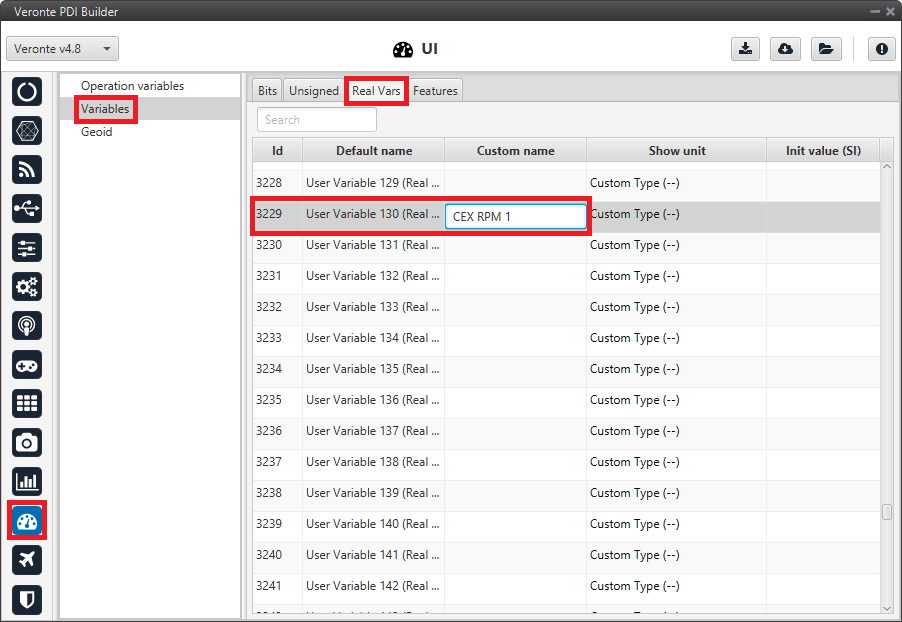
1x PDI Builder - User Variable renamed
Go to Input/Output menu \(\rightarrow\) CAN Setup panel \(\rightarrow\) Mailboxes tab.
Configure some mailboxes to receive the message with ID 1200:

1x PDI Builder - Mailbox configuration
Go to Input/Output menu \(\rightarrow\) CAN Setup panel \(\rightarrow\) Configuration tab.
Connect an Input filter to a Custom message consumer. Both CAN buses of the autopilot 1x can be used, as well as normal IDs and extended IDs:
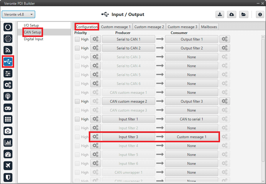
1x PDI Builder - Input filter
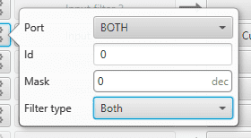
1x PDI Builder - Input filter configuration
Go to Input/Output menu \(\rightarrow\) CAN Setup panel \(\rightarrow\) Custom message 1 tab (as Custom Message 1 has been selected as consumer).
Configure the reading of the message and store the received value in the user variable renamed above:
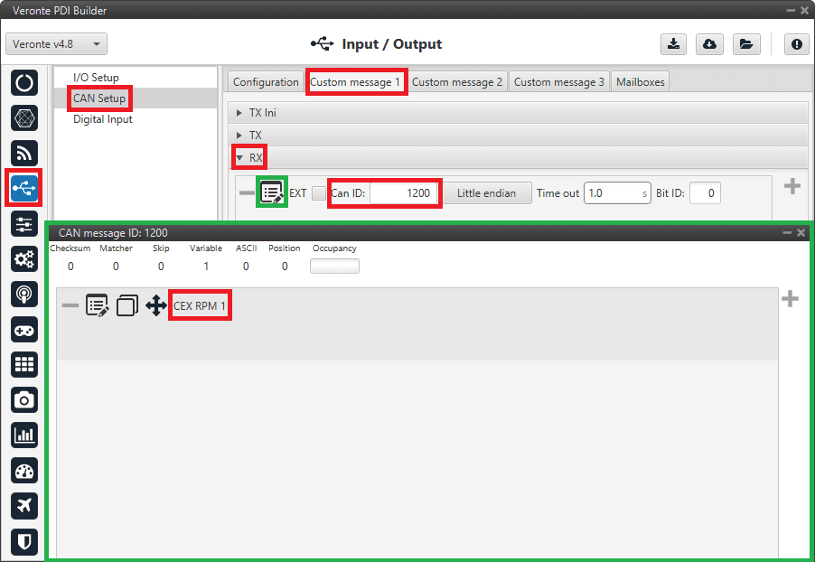
1x PDI Builder - Custom Message configuration
Serial communication
The user can send information through the serial ports of the CEX. For this purpose, please note the following explanation:
CEX PDI Builder side
I/O Setup configuration
Reception of serial information on UART-A (RS232-A) (producer) is stored in Serial to CAN 2 (consumer).
Transmission of serial information is sent using the CAN to Serial 2 (producer) via UART-A (consumer).
(‘Serial to CAN’ and ‘CAN to Serial’ are explained in the I/O section of this manual, click here to access it)
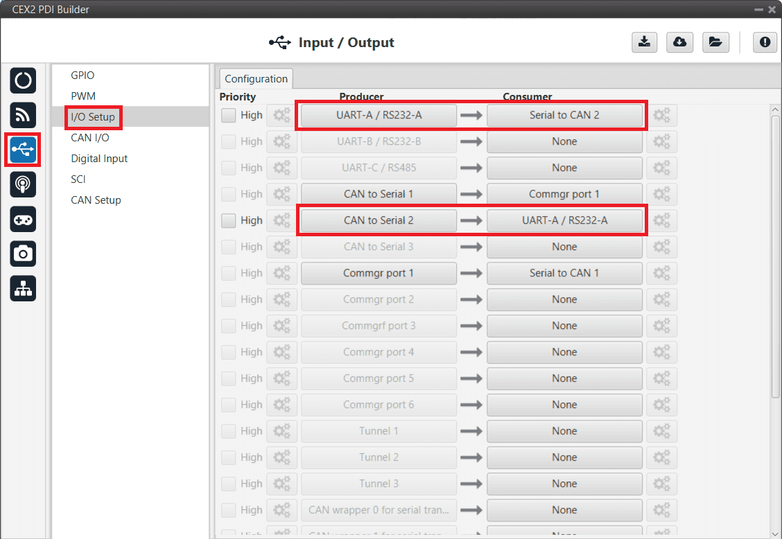
Serial - I/O Setup
CAN I/O configuration
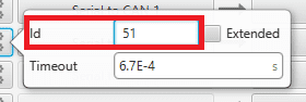
The information that will be sent via serial port UART-A is going to be received on the CEX through its CAN B port. A mask Id of 51 is added to the Input filter. The incoming information (from Veronte Autopilot 1x) is processed in ‘CAN to Serial 2’.
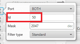
The information coming from port UART-A and processed as ‘Serial to CAN 2’ is going to be linked to an Output filter. The information of ‘Serial to CAN 2’ is going to be sent via CAN B with a mask ID of 50 (to be read by Veronte Autopilot 1x).
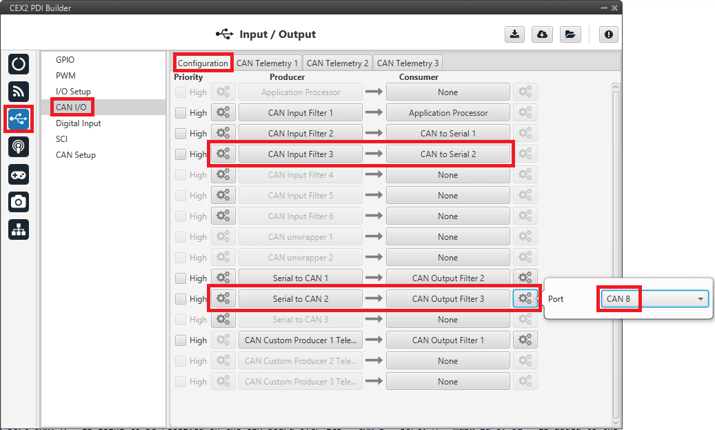
Serial - CAN I/O
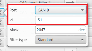
Serial - Input filter configuration
Serial - Serial to CAN configuration
CAN Setup (mailboxes) configuration
Mailboxes need to be defined for the reception of CAN messages. In the example above, mailboxes for ID 51 need to be added on CAN B port.
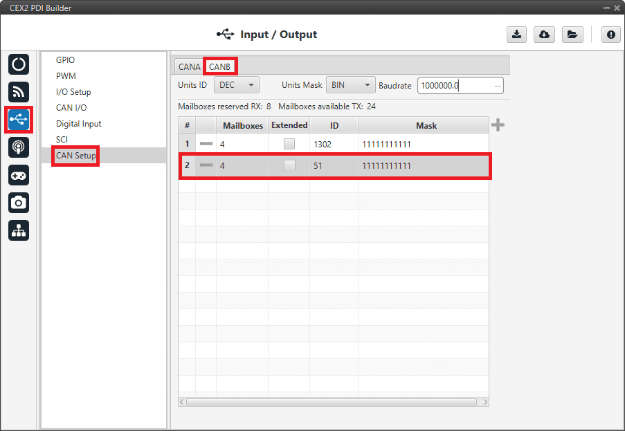
Serial - CAN Setup configuration
1x PDI Builder side
I/O Setup configuration
On the I/O Setup, link an ‘RS Custom Message’ to a ‘Serial to CAN’ with the serial data that the autopilot is going to send to CEX.
Then, link a ‘CAN to Serial’ to another ‘RS Custom Message’ with the expected serial messages that the CEX will receive in the selected serial port.
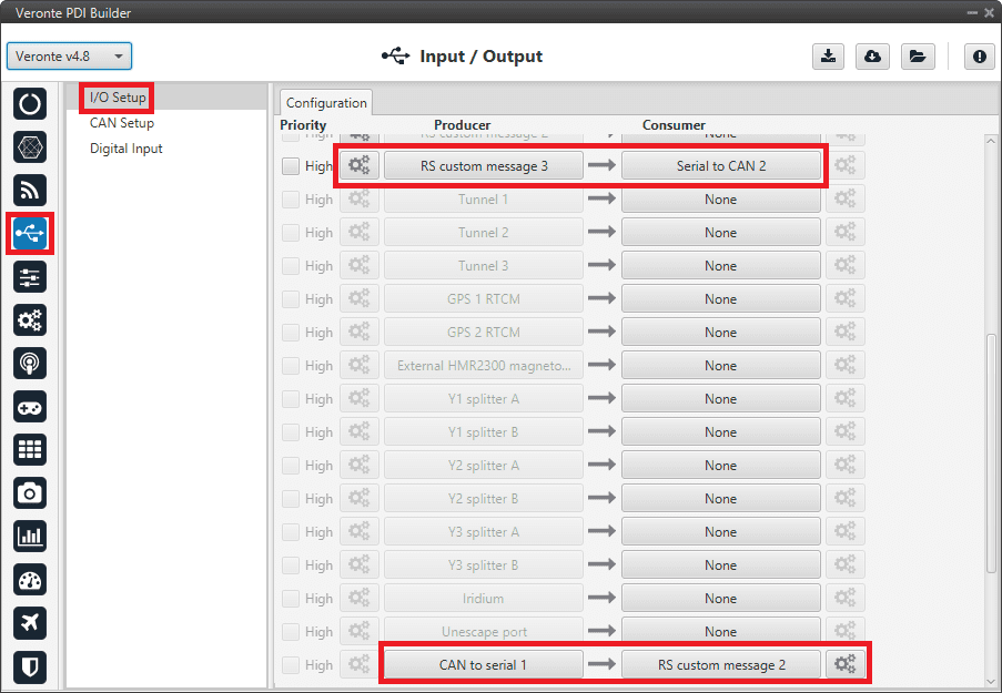
Serial - 1x I/O Setup configuration
CAN Setup configuration
As for the CAN I/O, the same IDs employed in CEX for the Input and Output filters are going to be employed on Veronte Autopilot 1x side, but they need to be inverted.
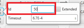
Therefore, the Input filter linked to the chosen ‘CAN to Serial’ needs to have ID 50. And the Output filter linked to the chosen ‘Serial to CAN’ will have ID 51.
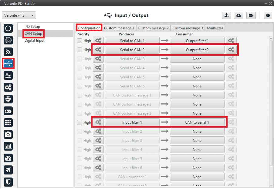
Serial - 1x CAN Seup
Serial - 1x Serial to CAN configuration
Serial - 1x Input filter configuration
Mailboxes configuration
Some mailboxes with ID 50 will have to be created on whichever chosen reception CAN bus.
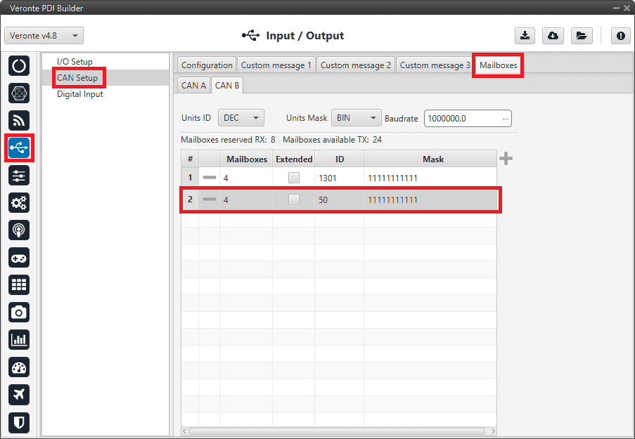
Serial - 1x Mailboxes configuration