UART
I/O Manager Configuration
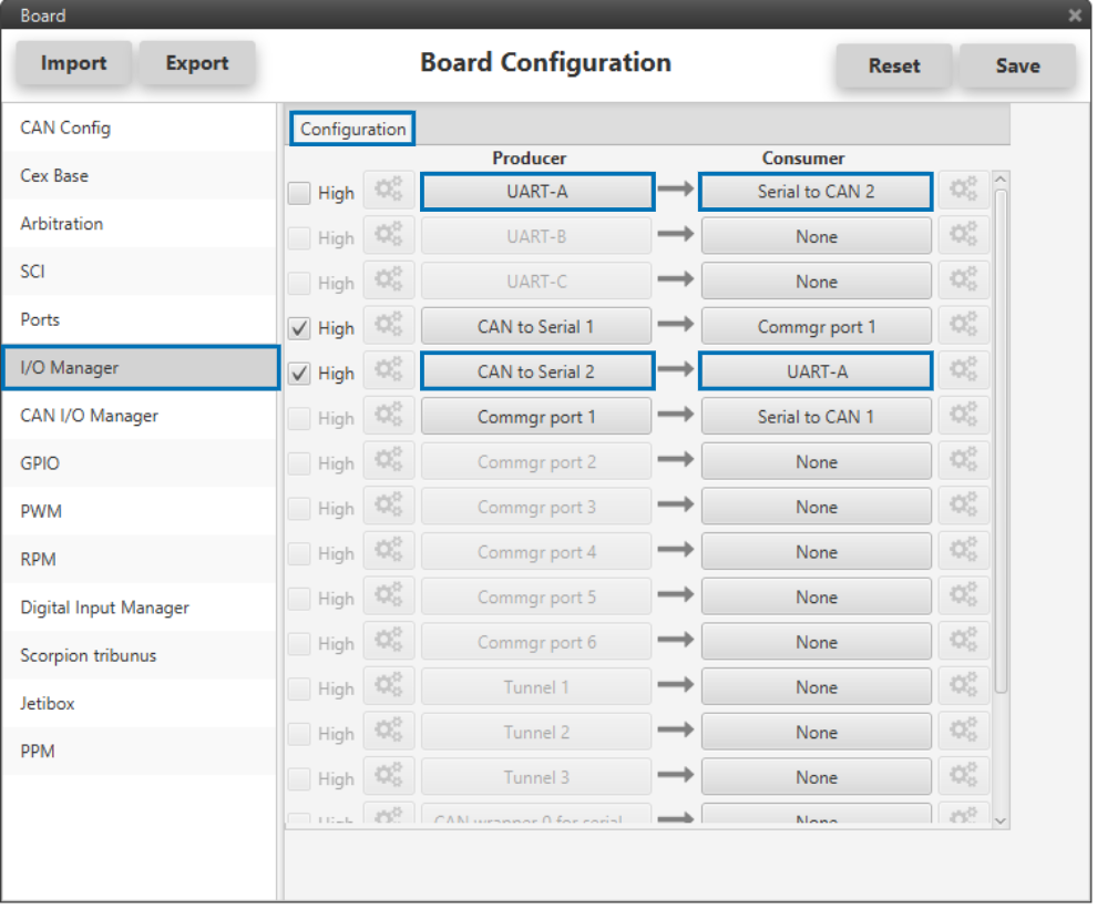
Reception of serial information on UART-A (producer) is stored in Serial to CAN 2 (consumer). Transmission of serial information is sent using the CAN to Serial 2 (producer) over UART-A (consumer).
‘Serial to CAN’ and ‘CAN to Serial’ configuration is explained in the CAN I/O Manager menu section below.
IO Manager Configuration
SCI
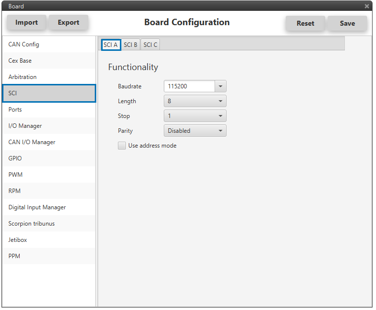
Serial ports A, B and C parameters can be edited in this menu to fit the serial protocol requirements. Ports A and B will be different depending on the CAN Expander version (2xUART in OEM version; 1x RS232 and 1xRS485 in MC version).
SCI-A Configuration
CAN I/O Manager Configuration
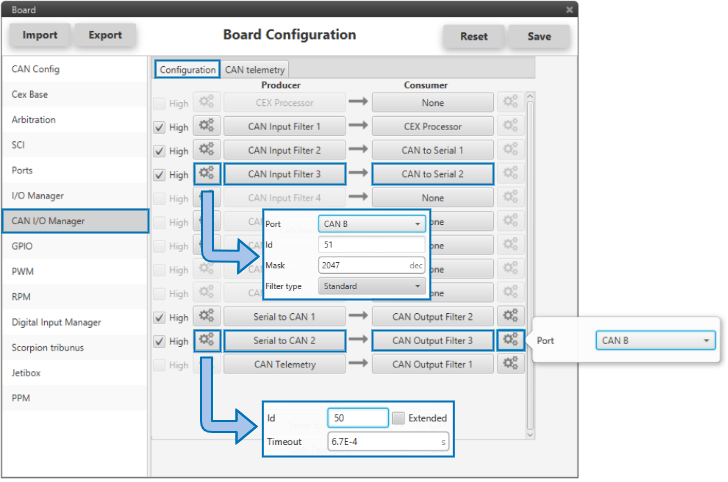
The information that will be sent over serial port UART-A is going to be received on the CAN Expander board over its CAN B port. A mask id of 51 is added to the Input filter. The incoming information (from Veronte autopilo) is processed in ‘CAN to Serial 2’.
The information coming from port UART-A and processed in the board as ‘Serial to CAN 2’ is going to be linked to an Output filter. The information of ‘Serial to CAN 2’ is going to be sent over CAN B of the board with a mask ID of 50 (to be read by Veronte autopilot).
CAN I/O Manager Configuration
On the CAN Expander board, as in with Veronte autopilot, mailboxes need to be defined for the reception of CAN messages. In the example above, mailboxes for ID 51 need to be added on CAN B port of the board.

CAN B Mailboxes
Veronte Autopilot Side
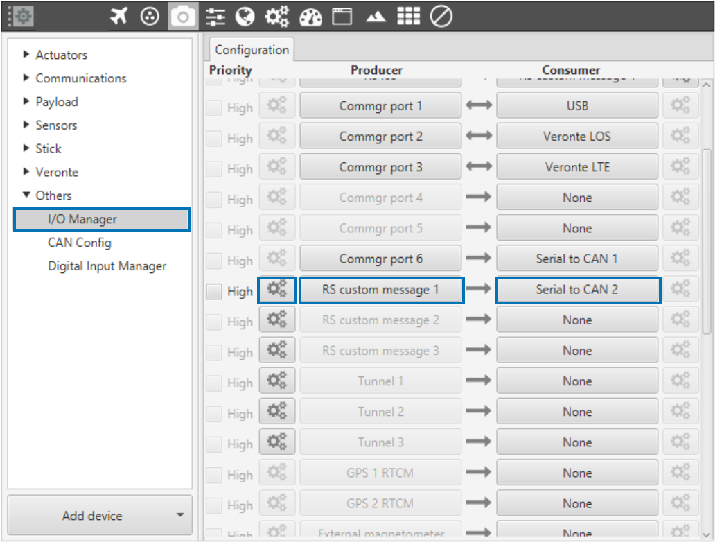
On the I/O Manager, link an ‘RS Custom Message’ to a ‘Serial to CAN’ with the serial data that the autopilot is going to send to the CAN Expander board. Then, link another ‘RS Custom Message’ to a ‘CAN to Serial’ with the expected serial messages that the CAN Expander board will receive in the selected serial port.
Veronte I/O Manager Configuration
As for the CAN I/O Manager, the same IDs employed in the CAN Expander board for the Input and Output filters are going to be employed on Veronte’s side, but they need to be inverted.
Therefore, the Input filter linked to the chosen ‘CAN to Serial’ needs to have ID 50. And the Output filter linked to the chosen ‘Serial to CAN’ will have ID 51. Some mailboxes with ID 50 will have to be created on whichever chosen reception CAN bus.