Reading RPMs
GPIO Configuration
RPM can be read on the available digital inputs I/O 1-4. The chosen pin needs to be configured as “GPIO as input”. In the example shown here, I/O1 is chosen (pin 9 on OEM version; pin 10 on MC version).
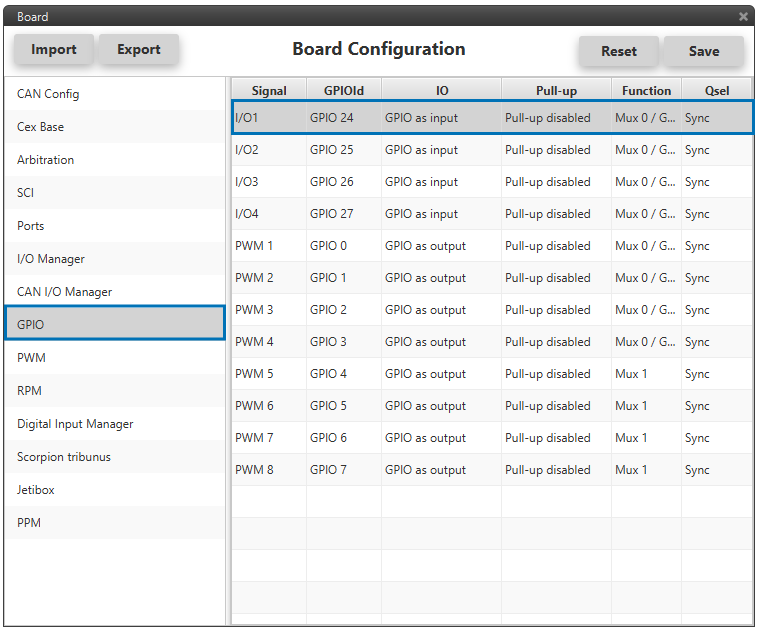
GPIO Configuration
Digital Input Manager
There are 4 possible producers: CAP 1 - 4. One needs to be chosen and linked to one of the RPMs consumers, PPS 1 - 4 (Pulse Per Second). Then, each chosen producer needs to be pointing to the right I/O (in this example, I/O1). Lastly, the expected pulse needs to be wrapped: for RPMs the desired options are “first rising edge” or “first falling edge”.
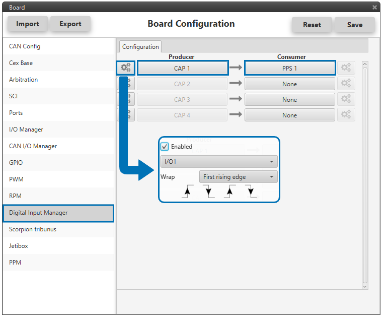
Digital Input Manager Configuration
RPM Configuration Menu
Here the expected pulse needs to be defined. There are 4 tabs (RPM 1 - 4). The user needs to select the tab according to the chosen consumer in the Digital Input Manager. In the example, PPS1 was chosen, therefore RPM1 will be edited.

RPM: Pulse Data
The data available is:
Units: avaialble options are pulses per cycle, radians per pulse or custom.
Average filter: the readout of the pulse can be filtered for the output to be an average. The amount of measurements to do the average needs to be specified.
Minimum pulse: here the minimum expected pulse period needs to be specified. This will discard spurius pulses (e.g. induced by EMI) which are smaller than this minimum pulse.
Maximum time without capture: if no incoming pulse is received for more than this time, the output RPMs will be 0.
CAN Telemetry
Last, the RPMs sensed need to be sent to the autopilot. In the CAN I/O Manager a new telemetry message needs to be created with its correspondent ID, endianness and period. In the example below:
ID: 1200.
Endianness: little.
Period: 0.01 s.
In the telemetry message one of CEX’s variables needs to be selected. As we have chosen PPS1 as our consumer in the Digital Input Manager, the variable we need to send is RPM1.
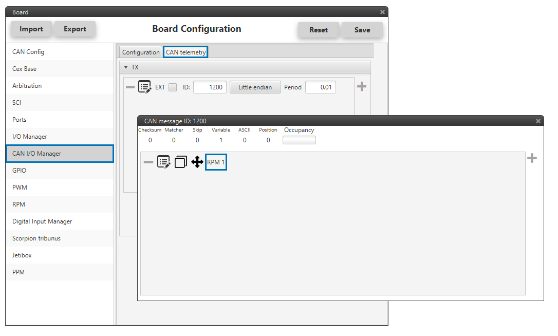
RPM: CAN Telemetry
The telemetry (producer) needs to be send over one of the avialable CAN Output Filters (consumer). In the example below, the RPM1 variable is sent over CAN B bus of the CEX.
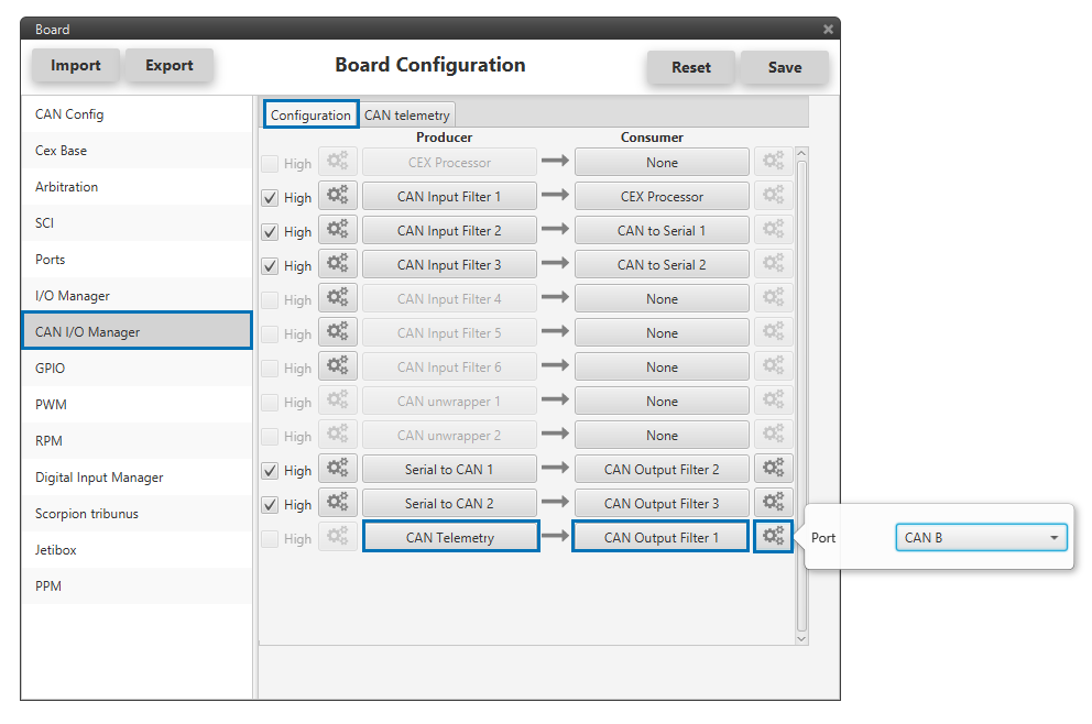
RPM: CAN Telemetry I/O Configuration
On the autopilot side, some mailboxes with ID 1200 will have to be created on whichever chosen reception CAN bus.
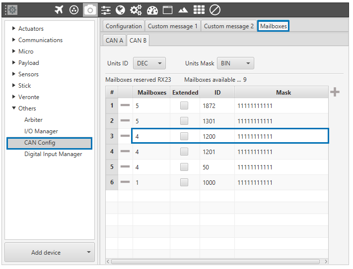
RPM: Mailboxes Assigned on the Autopilot
Accordingly, the 4 bytes information contained in RPM1 will have to be stored in one of the available 300 real user variables (32 bits).
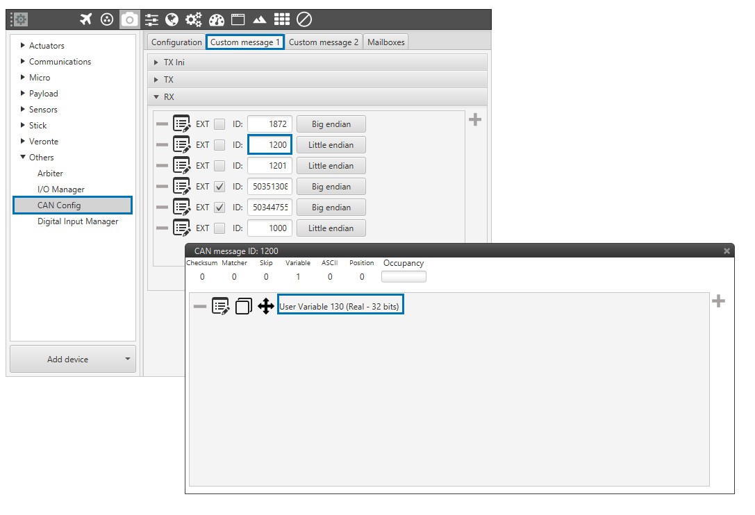
RPM: CAN Telemetry on the Autopilot
An input filter is used (producer) and the information is being received on the Custom Message 1 (producer). Both CAN buses of the autopilot can be used, as well as normal IDs and extended IDs.
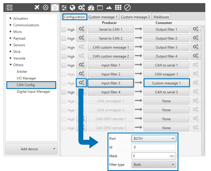
RPM: CAN Telemetry I/O Configuration on the Autopilot