Troubleshooting
In case of any issue with software, read the Troubleshooting section of the 1x PDI Builder user manual.
Maintenance mode
Maintenance mode is the main recovery mode that Veronte system puts at the user disposal. The main use of maintanance mode is to solve issues related to the current configuration, mainly related with communication or memory writting issues.
While in maintenance mode, all communications channels are enabled by default, so it is possible to connect Veronte Autopilot 1x through any of its configuration interfaces, regardless of its current configuration. Thus allowing to re-establish communications with it in case they have been lost for any reason.
Tip
It is heavily recommended to always use maintenance mode to load a new configuration that is very different from the current one.
Warning
Autopilot 1x might enter in maintenance mode if a problem with the power supply is detected upon boot up (voltage or current is out of range).
How to enter in maintenance mode
There are two ways to enter in maintenance mode: by software or hardware (forcing it).
Using software to enter in maintenance mode
To enter in maintenance mode by software, read the Maintenance Mode - Troubleshooting section of the 1x PDI Builder user manual.
Forcing maintenance mode
There are two ways to force the maintenance mode: using power supply or using the I2C pins.
Power supply
In order to active maintenance mode, power cycle the Veronte Autopilot 1x repetively with periods of 700 ms (with a margin range between 380 and 965 ms). After 30 cycles, the autopilot will enter in maintenance mode.
I2C pins
To enter in maintenance mode with I2C:
- Unplug Veronte Autopilot 1x
- Connect both I2C pins each other
- Then, power up Autopilot 1x
- Finally disconnect both pins
Both pins are I2C_CLK (number 31) and I2C_DATA (number 32) according to the pinout.
Note
Dev Harness 1x 4.8 (Embention reference P007043) has already included a button with this 2 pins to easily enter maintenance mode.
The procedure is the same as for the pins, but instead of connecting and disconnecting the pins, press and release the button.
Half-duplex servo does not respond
Any servo with half duplex RS-485 should communicate with Autopilot 1x following the connection diagram:
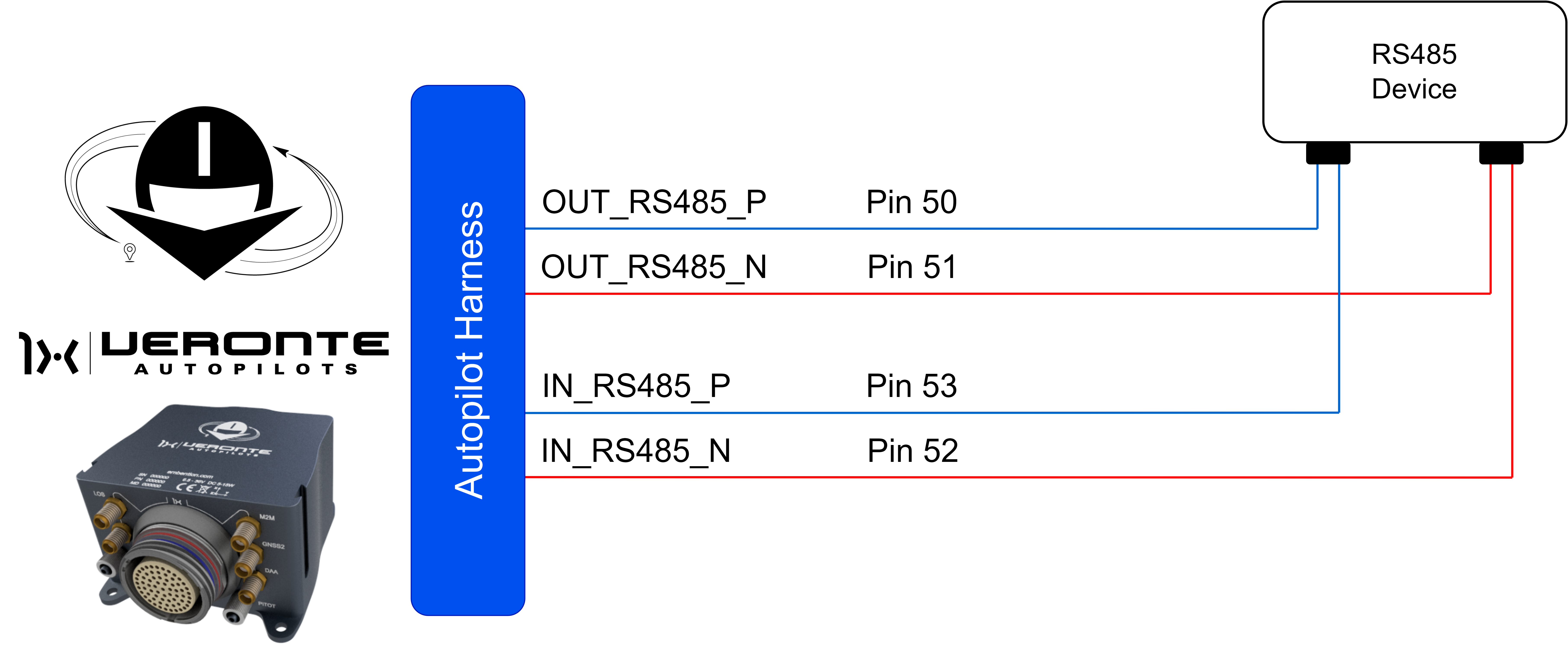
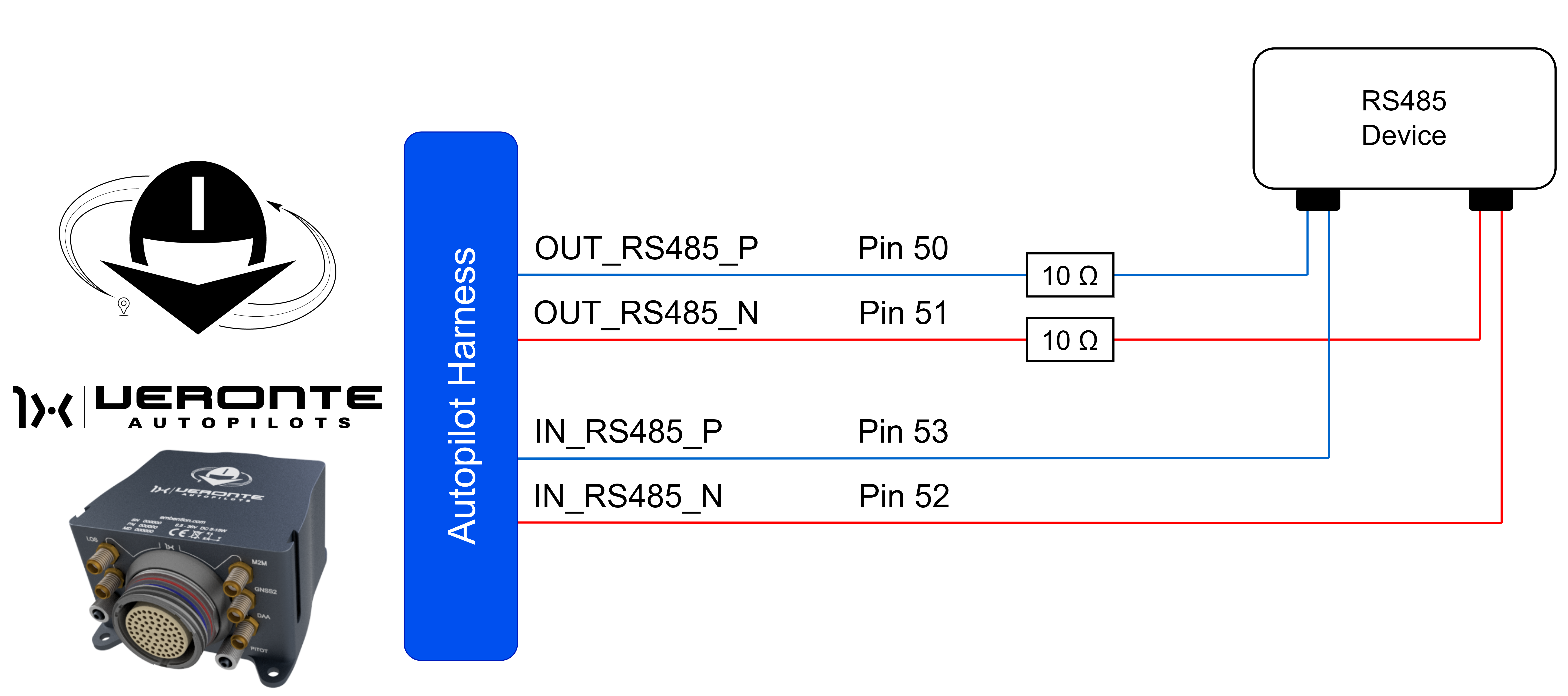
Sometimes this connection does not work, because the servo has not enough transmission power. In this case, a couple of 10 resistors may solve the problem. Both resistors have to be placed at the trasmission line of the Autopilot 1x.
If the couple of resistors does not solve the issue, the user should contact the support team (create a ticket in the customer's Joint Collaboration Framework; for more information, see Tickets section of the JCF manual).
UDP Failed Connection
If setting up the autopilot with an RS-485 connection via UDP on port 5002, and it is not detected by Veronte Link, please check the following steps:
-
Open Wiznet Software and check Remote Port.

WIZnet Configuration Panel -
Change Remote Port 5002 to a different port. In this example, Remote Port 52000 is set.

WIZnet Configuration Panel -
Afterward, configure the UDP Connection in Veronte Link with the same parameter value.

UDP Connection settings -
Click on Save.
© 2026 Embention. All rights reserved.