Troubleshooting
Debug serial messages transmission
To check that the transmission of serial messages is being carried out correctly, the user can view what is being sent in the 1x PDI Calibration software hyperterminal. To do this:
1x PDI Builder side
-
Go to Input/Output menu I/O Setup panel.
Connect the RS custom message producer (where the message is configured) to a Tunnel with Address 2 (App 2).
In this case, the message is configured in the RS custom message 0 producer and sent through Tunnel 0.
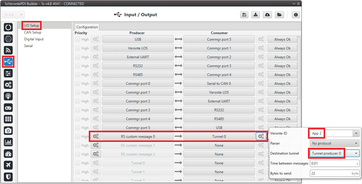
RS custom message → Tunnel
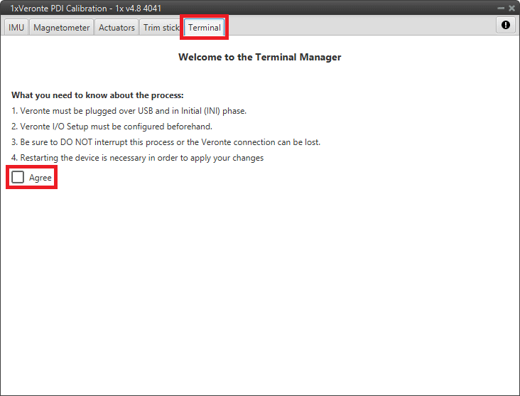
1x PDI Calibration side
-
Go to Terminal tab.
Click on Agree:
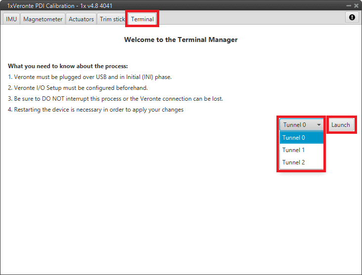
Terminal tab -
Next, select the Tunnel 1 (this corresponds to the Tunnel 0 that has been configured in the 1x PDI Builder, as the numbering here starts at 1 and not 0) and click on Launch:
Terminal tab - Tunnel selected The tunnel console should open and the user will be able to view the message being sent:
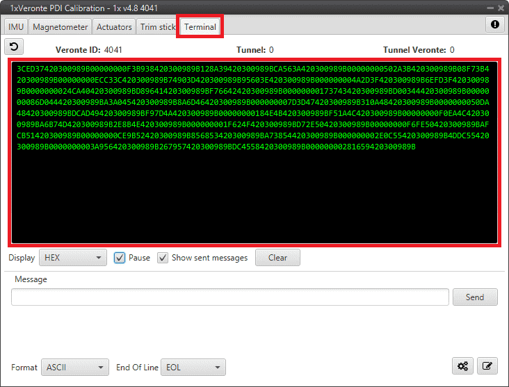
Tunnel console For more information on the Terminal configuration, please refer to the Terminal section of the 1x PDI Calibration user manual.
Internal Digi radio
If users are having problems communicating with the Digi radio, consider the following checks:
-
Review Autopilot 1x configuration: Ensure that all parameters are correctly configured according to the specifications detailed in the Digi internal radio - Integration examples section of this manual.
-
Adjust XCTU settings: Check that the parameters set in the XCTU software match the specifications detailed in Configuration in Digi radio software of the Digi internal radio integration example. Pay special attention to step 9.
These steps can help identify and fix any configuration errors that prevent communication.
Communication lost with internal Digi radio
Most of the time, the communication between Autopilot 1x and Digi radio is lost due to a change in its baudrate.
In 1x PDI Builder it is set to 115200 by default, however, in Digi radios the factory default baudrate at reset is 9600.
To recover communication, try changing the baudrate on one of them to match.
-
Go to Input/Output menu Serial panel Veronte LOS tab.
Set the Baudrate on Veronte LOS to 9600.
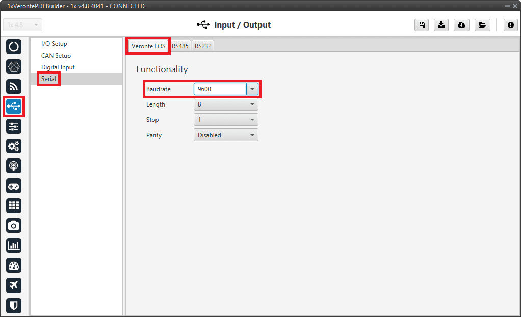
Veronte LOS baudrate -
Check the steps described in the Digi internal radio - Integration examples section to see if the module is now detected in XCTU software.
Then, if desired, the user can change the radio baudrate to 115200 and after that also change it for Veronte Autopilot 1x.
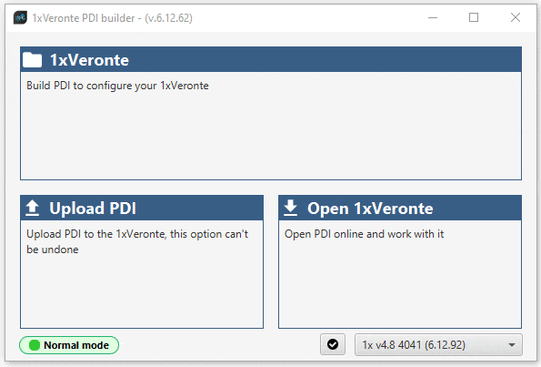
Maintenance mode
The user can simply enter maintenance mode via 1x PDI Builder by clicking on the "Normal mode" button in the initial menu. In addition, exiting maitenance mode is the same process.
Below is an example of how to do this:
Maintenance mode (loaded with errors)
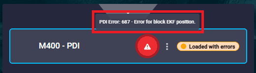
The following error message may appear when trying to save a change or import a configuration.
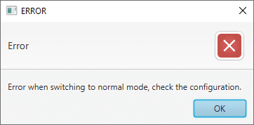
Therefore, Veronte Autopilot 1x will be in 'Maintenance mode (loaded with errors)':
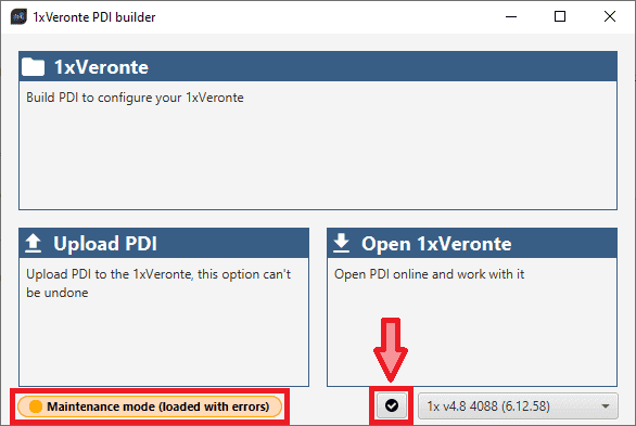
To check what the source of the problem is, the user can simply click on the PDI Error button ![]() , which will show what the PDI Error is:
, which will show what the PDI Error is:
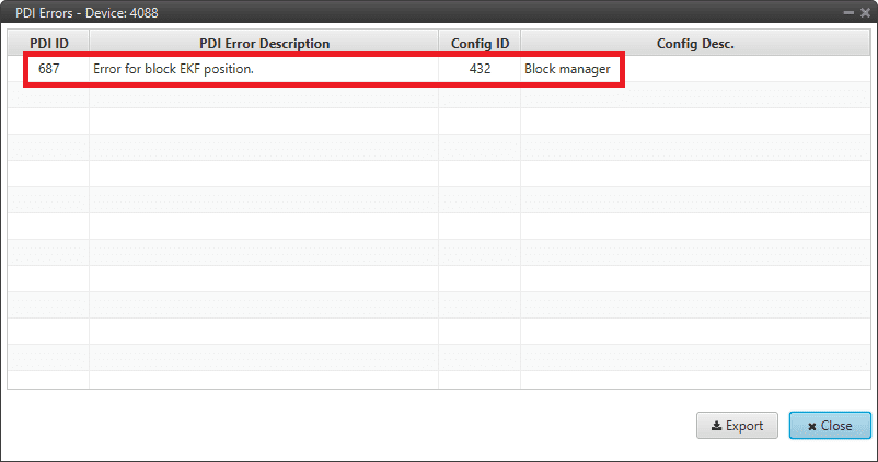
- PDI ID: ID of the PDI Error.
-
PDI Error Description: Description of this PDI Error. A list of all PDI Errors can also be accessed in the List of PDI Errors - Lists of interest section of the 1x Software Manual.
-
Config ID: ID of the configurable (.xml file) containing the data in which the PDI Error has been caused.
- Config Description: Description of the configurable (.xml file) containing the data in which the PDI Error has been caused.
Clicking the Export button will export a .csv file with the same information shown in this PDI Errors panel.
This is useful while the configuration is in progress, however, if the user encounters this situation during the operation, it is also possible to look up the cause of the PDI Error directly on the Platform panel of Veronte Ops. For more information about this panel, see Platform panel section of the Veronte Ops user manual.
Then, it is possible to access the Autopilot 1x configuration to fix this error.
Tip
If the PDI error is related to a migration, it is usually caused by the selection of accelerometer, gyroscope and magnetometer sensors.
In addition, a list of all PDI Errors can be accessed in the List of PDI Errors - Lists of interest section of the 1x Software Manual.
Migrate configuration
Warning
When performing automatic migration from a previous version to the current version of the software, errors may occur.
It is then the responsibility of the user to check the subsequent result.
Radios paired but 1x air unit not showing
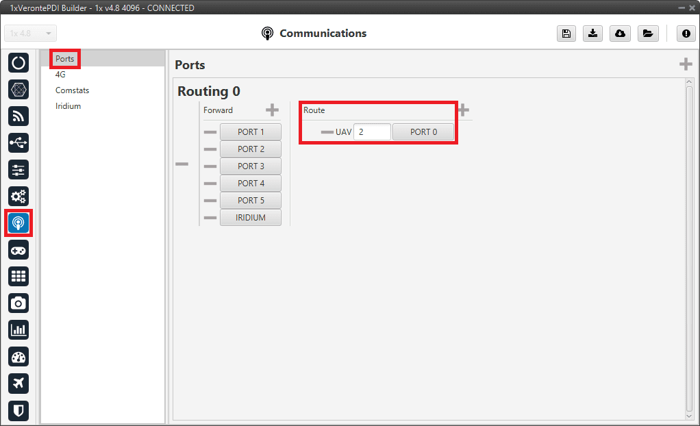
If the radios of both Autopilots 1x, air and ground units, are paired but the 1x air unit does not appear connected in Veronte Link, it may be because the routing on the 1x ground unit is not correctly configured. Therefore, users should check the Ports configuration on the 1x ground unit. To do this:
Go to Communications menu Ports panel, and the routing of address 2 (address by which Autopilots 1x ground and air units communicates with all Veronte applications, such as Veronte Link) must be set to the port that is connected to the USB (PC connection), in this case it is PORT 0.
Reducing GNC Task frequency
400 Hz is the maximum possible frequency, but can only be used in simple configurations, in other cases it is advisable to reduce it to 250-300 Hz.
To find out if the frequency needs to be reduced in the user configuration, check the GNC Task Average CPU Ratio variable.
For correct operation, this variable should be at approximately 60-70%. If it reports a higher value, the frequency must be lowered.
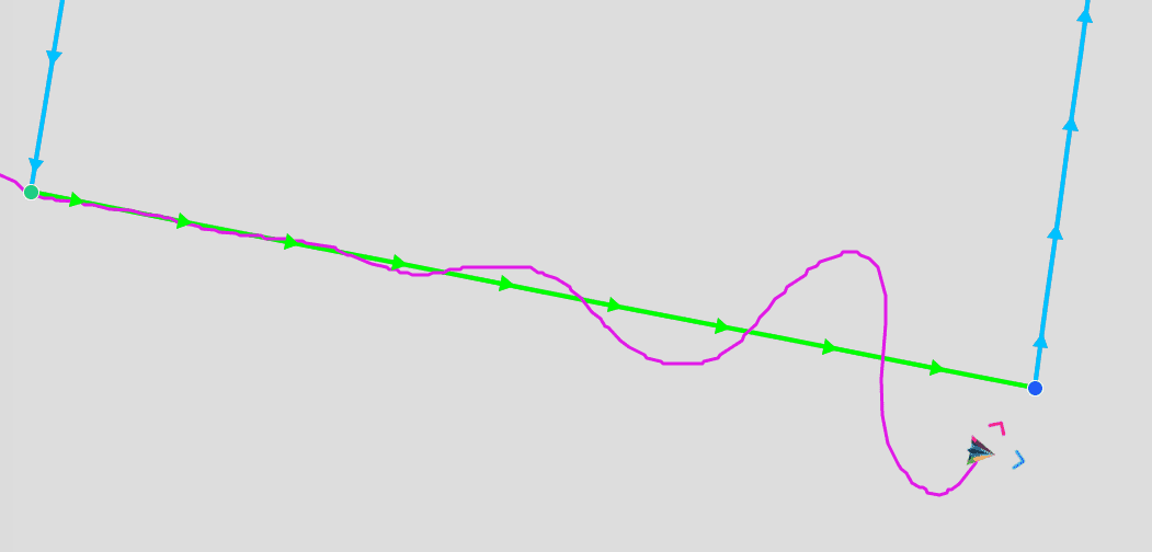
Trajectory Overshoot
If the user observes significant meandeling or overshoot in the mission path, this can be reduced by modifying the gains of the guidance PIDs:
- Reducing the proportional gain.
- Ensure that the integral gain is 0.
Guidance error accumulates and leads to increasing overshoot, as can be seen in the following example:
© 2026 Embention. All rights reserved.