Hardware Changelog
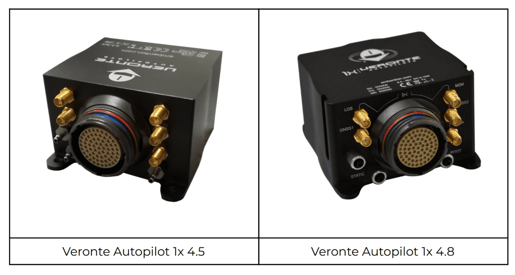
Hereby are described the main differences between the latest release of the Veronte Autopilot 1x hardware (v 4.8) and the previous commercial version (v 4.5).
Specifications
| Mechanical | ||
|---|---|---|
| 4.5 | 4.8 | |
| Mating connector | Circular mating connector with 68 pins | |
| Enclosure | Anodized aluminum | |
| Weight | 190 g | 198 g |
| Dimensions | 78 x 63 x 40 mm | 76 x 65 x 40 mm |
| Protection rating | IP67 | |
| Mounting | M4 screws | M3 screws |
| Temperature range (no convection) | -40 to 65 ºC | |
| Pressure port | 2.4 mm | SMC M5 series system. Usable with 2.5 x 4 mm polyurethane |
| RF connectors (LOS/BLOS/GNSS) | SSMA jack female | |
| Sensors | ||
|---|---|---|
| 4.5 | 4.8 | |
| Number of static pressure sensors | 3 | 2 |
| Static pressure range |
0) 0 - 103,000 Pa 1) 1,000 - 120,000 Pa 2) 30,000 - 120,000 Pa |
1) 1,000 - 120,000 Pa 2) 30,000 - 120,000 Pa |
| Static pressure band error |
0) 1,030 Pa 1) 500 Pa 2) 200 Pa |
1) 500 Pa 2) 200 Pa |
| Static pressure resolution |
0) 25 Pa 1) 1.2 to 6.5 Pa 2) 0.5 Pa |
1) 1.2 to 6.5 Pa 2) 0.5 Pa |
| Number of dynamic pressure sensors | 1 | |
| Dynamic pressure range | 3 Pa (5 kt 8 km/h sea level) to 6,900 Pa (206 kt 382 km/h sea level) | |
| Dynamic pressure band error | 0.01 % | |
| Dynamic pressure resolution | 25,500 Pa | |
| Number of accelerometers (3 axis each) | 2 | 3 |
| Accelerometer range |
1) ±16 g 2) ±24 g |
1) ±16 g 2) ±24 g 3) ±8 g |
| Accelerometer max. shock |
1) 20,000 for 0.2 ms 2) 10,000 g/ms |
1) 20,000 g for 0.2 ms 2) 10,000 g/ms 3) 14,700 m/s² |
| Accelerometer sensitivity |
1) 16,393 LSB/(m/s²) 2) 10,920 LSB/(m/s²) |
1) 16,393 LSB/(m/s²) 2) 10,920 LSB/(m/s²) 3) 26,756,268 LSB/(m/s²) |
| Number of gyroscopes (3 axis each) | 2 | 3 |
| Gyroscope range |
1) 125 to 2,000 º/s 2) 125 to 2,000 º/s |
1) 125 to 2,000 º/s 2) 125 to 2,000 º/s 3) 2,000 º/s |
| Gyroscope sensitivity |
1) 228 to 14.2 LSB/º/s 2) 262 to 16 LSB/º/s |
1) 228 to 14.2 LSB/º/s 2) 262 to 16 LSB/º/s 3) 655,360 to 10 LSB/º/s |
| Number of magnetometers | 2 | 3 |
| Magnetometer range |
1) 4 gauss 2) 8 gauss |
0) 4 gauss 1) 8 gauss 2) 11 gauss |
| Magnetometer sensitivity |
1) 6,842 to 1,711 LSB/gauss 2) 4,096 LSB/gauss |
0) 6,842 to 1,711 LSB/gauss 1) 4,096 LSB/gauss 2) 0.13 mgauss |
| Number of GNSS units | 2 | |
| GNSS constellations | BeiDou, GLONASS, GPS | BeiDou, Galileo, GLONASS, GPS/QZSS |
| Concurrent GNSS constellations | Up to 2 | Up to 4 |
| GNSS bands | L2OF, L2C, E1B/C, B2l, E5b, L1C/A, L1OF, B1l | |
| Position accuracy RTK | 0.025 m + 1 ppm CEP | > 0.01 m + 1 ppm CEP |
| Update rate | 8 Hz | up to 20 Hz |
| I/O (on base hardware - expansion boards available) | ||
|---|---|---|
| 4.5 | 4.8 | |
| Vin | 2 x (6.5 - 36 V) DC | |
| PWM / GPIO | Up to 16 | |
| RS232 | 1 x | |
| RS485 | 1 x | |
| Vout | 5 & 3.3 V | |
| FTS | Deadman output (GPIO) | |
| CAN bus | 2 x | |
| ADC | 5 x | |
| EQEP | 1 x | |
| I2C | 1 x | |
| UART | 1 x (FTS - SuC) | 1 x Microcontroller (i.e. external datalink) |
| USB | 1 x | |
Architecture and Computing Power
Veronte Autopilot 1x 4.8 and 4.5 share the same internal architecture, powered by the same dual core microprocessor from the Texas Instruments EP (Enhanced Performance) series.
Line of Sight Communications
Veronte Autopilot 1x 4.5 had the possibility to install internal datalinks from Microhard (Pico Series), available in 2.4 GHz, 900 MHz and 400 MHz. In the new version (4.8), this datalink has been replaced by a short range module for testing, configuration and telemetry download.
Embention has decided to replace the 1W Microhard datalink for the following reasons:
- As per past experience, each aircraft manufacturer has different datalink needs, so Embention has preferred that customers can have more flexibility choosing the appropriate brand, model and frequency.
- By removing the Microhard modules, there is now more space to include better sensors with extended accuracy.
- Reducing the power of the internal RF module from the autopilot permits to reduce electromagnetic interferences.
- Reducing the power consumption also reduces the heat dissipation needs on the autopilot and improves performance in warm environments.
Thus, Autopilot 1x 4.8 internal datalink has been replaced by Digi XBee® 3 PRO Zigbee 3.0, a 2.4 GHz short range module. This module has the mission to allow the integration and PDI tuning of the autopilot into the customer's platform. An external datalink (Microhard or others) can be installed in the additional UART port available in 4.8.
| Performance for Digi XBee® 3 PRO Zigbee 3.0 | |
|---|---|
| Data rate | RF 250 kbps, serial up to 1 Mbps |
| Indoor/urban range | Up to 300 ft (90 m) |
| Outdoor/RF line-of-sight range | Up to 2 miles (3200 m) |
| Transmit power | +19 dBm |
| Receiver sensitivity (1% PER) | -103 dBm normal model |
| Features | |
|---|---|
| Frequency band | ISM 2.4 GHz |
| Interference immunity | DSSS (Direct Sequence Spread Spectrum) |
| Networking and Security | |
|---|---|
| Protocol | Zigbee 3.0 |
| Encryption | 128/256 bit AES |
| Reliable packet delivery | Retries / acknowledgements |
| IDS | PAN ID and addresses, cluster IDs and endpoints (optional) |
| Channels | 16 channels |
New Features
One of our fundamentals at Embention is the continuous evolution of our products and services. The UAM sector is evolving everydays and new needs and technical requirements are demanded almost every week. For this reason, in order to help our customers to achieve their goals, Embention has released a new version of its hardware, with the following features.
-
Enhanced sensor accuracy and reliability: Dead reckoning navigation is a critical tool for degraded GNSS scenarios, the new sensors in Veronte Autopilot 1x are significantly more accurate than previous ones.
These enhanced sensors allows to improve the navigation estimation during the standard operation and in GNSS denied navigation.
-
Improved RTK and GNSS heading: New GNSS sensors in Veronte Autopilot 1x are significantly better in various aspects (supported constellations, accuracy, number of concurrent constellations and frequency).
The positioning accuracy has improved from 0.025 m + 1 ppm to 0.01 m + 1 ppm CEP, it also improves RTK and GNSS heading estimation.
-
Enhanced high-temperature hardware design and production materials: In order to offer the best performances in extreme scenarios and to pass more demanding quality and environmental tests.
New materials are used in PCB manufacturing. These new fibers have better performance in heat conditions, extending the lifetime of the product.
-
Additional failure detection means: Development of failure detection algorithms and redundant hardware.
The new PCB design includes additional signals for failure detection that can communicate each one of the autopilot cores with the arbiter. Also, the internal CAN Bus network has been modified to enhance robustness.
-
Short-range 2.4 GHz LOS included in all units: Short range communications module included, in order to facilitate system integration.
This module is based on Digi Xbee and permits to have an independent link for telemetry download and configuration.
-
BLOS module with extended coverage: BLOS communications and UTM capabilities through a physical or eSIM card.
-
Extended GNSS-denied navigation capabilities: Flexible and custom Kalman filters, high precision IMU sensors and several tools in order to build safety automations if GNSS is lost.
Inertial navigation highly depends on the IMU accuracy, which has been significantly improved with the new setup.
-
Internal Remote ID or ADS-B with IN/OUT: Extended collaborative sense and avoid capabilites, allowing the compliance of new FAA unmanned operation requirements.
WIFI and Bluetooth modules have been integrated to enable Remote ID communications. This module can be replaced by a 1W ADS-B IN & OUT module if preferred.
-
Embedded global DEM, geoid, magnetic and gravity fields: Advanced custom possibilites for the user during the map configuration, in order to carry out high-accuracy operations in the safest way possible.
Worldwide terrain altitude and magnetic field are included in Veronte Autopilot 1x.
-
Internal enclosure pressure port: A new pressure port has been included for measuring the pressure inside the autopilot.
Collaborative Sense & Avoid and UTM
Some of the most important aeronautical authorities in the world have been very clear about the future lines in the certification process: all aircraft have to have collaborative detection capabilities. For example, the American FAA has expressed in several documents that a Remote ID system for drone identification and detection for smaller drones. For larger drones, it is expected that the ADS-B technology will prevail.
Remote ID
Remote ID is a young technology based on personal area networks (Bluetooth) and local area networks (WiFi). The system is emitting a constant signal with the ID of the drone and its positioning at each moment. Users can see the track of the operation and customers have the ability to configure the information shown.
| Frequency | WiFi & Bluetooth bands |
| Developed according to | RIN 2120-AL31 Remote identification of Unmanned Aircraft FAA Standard |
| Parameters | Aircraft ID, position, altitude and time mark |
| Compatibility | FAA Remote ID Scanner App |
To comply with the final rule of Remote Identification of Unmanned Aircraft (Part 89), manufacturers need to produce standard Remote ID drones and meet the requirements of this rule by September 16th, 2022.
Embention's Remote ID is being adapted in order to be in complicance with Active Standard ASTM F3411 requirements, developed by subcommittee F38.02.
ADS-B
Internal ADS-B with IN & OUT capabilities is another option in order to reach the collaborative detection capabilities and to enhance the fleet management performance.
| Frequency band | 1090 MHz |
| Current consumption | Averaged 140 mA |
| Sensitivity | -80 dBm |
| RF output power | Configurable + 30 dBm (1W), + 27 dBm (0.5 W), + 24 dBm (0.25 W) |
| ESD protection | All lines protected |
| MAVlink (baud) | 115200 bps |
| AERO (baud) | 115200 bps (AT commands) |
Pinout changes from Autopilot 1x 4.5
The pinout for 4.5 and 4.8 versions are very similar, but they have several differences.
To prevent any confusion, the following table shows the pinout for both versions. The different pins are marked with ⚠️, all the rest have the same function.

| PIN | Signal | Type | Description |
|---|---|---|---|
| 1 | I/O0 | I/O | PWM / Digital I/O signal (0-3.3V). Protected against ESD and short circuit |
| 2 | I/O1 | I/O | PWM / Digital I/O signal (0-3.3V). Protected against ESD and short circuit |
| 3 | I/O2 | I/O | PWM / Digital I/O signal (0-3.3V). Protected against ESD and short circuit |
| 4 | I/O3 | I/O | PWM / Digital I/O signal (0-3.3V). Protected against ESD and short circuit |
| 5 | I/O4 | I/O | PWM / Digital I/O signal (0-3.3V). Protected against ESD and short circuit |
| 6 | I/O5 | I/O | PWM / Digital I/O signal (0-3.3V). Protected against ESD and short circuit |
| 7 | I/O6 | I/O | PWM / Digital I/O signal (0-3.3V). Protected against ESD and short circuit |
| 8 | I/O7 | I/O | PWM / Digital I/O signal (0-3.3V). Protected against ESD and short circuit |
| 9 | GND | GROUND | Ground signal for actuators 1-8 |
| 10 | I/O8 | I/O | PWM / Digital I/O signal (0-3.3V). Protected against ESD and short circuit |
| 11 | I/O9 | I/O | PWM / Digital I/O signal (0-3.3V). Protected against ESD and short circuit |
| 12 | I/O10 | I/O | PWM / Digital I/O signal (0-3.3V). Protected against ESD and short circuit |
| 13 | I/O11 | I/O | PWM / Digital I/O signal (0-3.3V). Protected against ESD and short circuit |
| 14 | I/O12 | I/O | PWM / Digital I/O signal (0-3.3V). Protected against ESD and short circuit |
| 15 | I/O13 | I/O | PWM / Digital I/O signal (0-3.3V). Protected against ESD and short circuit |
| 16 | I/O14 | I/O | PWM / Digital I/O signal (0-3.3V). Protected against ESD and short circuit |
| 17 | I/O15 | I/O | PWM / Digital I/O signal (0-3.3V). Protected against ESD and short circuit |
| 18 | GND | GROUND | Ground signal for actuators 9-16 |
| 19 | RS 232 TX | Output | RS 232 Output (-13.2V to 13.2V Max, -5.4V to 5.4V Typical). Protected against ESD and short circuit |
| 20 | RS 232 RX | Input | RS 232 Input (-25V to 25V Max, -0.6V Low and 2.4V High Threshold). Protected against ESD and short circuit |
| 21 | GND | GROUND | Ground signal for buses |
| 22 | ANALOG_3 | Input Analog | Input 0-3.3V. Protected against ESD and short circuit |
| 23 | ANALOG_4 | Input Analog | Input 0-3.3V. Protected against ESD and short circuit |
| 24 | GND | GROUND | Ground signal for buses |
| 25 | CANA_P | I/O | CANbus interface, up to 1Mbps (2.3V Typical, 1.2V-2.3V Differential). Protected against ESD |
| 26 | CANA_N | I/O | Twisted pair with a 120 ohms Zo recommended (2.3V Typical, 1.2V-2.3V Differential). Protected against ESD |
| 27 ⚠️ |
4.5: GND |
4.5: GROUND |
4.5: Ground signal for buses |
4.8: 4XV_WD |
4.8: I/O |
4.8: Reserved. Do not connect |
|
| 28 | CANB_P | I/O | CANbus interface. It supports data rates up to 1 Mbps. Protected against ESD |
| 29 | CANB_N | I/O | Twisted pair with a 120 ohms Zo recommended. Protected against ESD |
| 30 | GND | GROUND | Ground signal for buses |
| 31 | I2C_CLK | Output | Clk line for I2C bus (0.3V to 3.3V). Protected against ESD and short circuit |
| 32 | I2C_DATA | I/O | Data line for I2C bus (0.3V to 3.3V). Protected against ESD and short circuit |
| 33 | GND | GROUND | Ground for 3.3V power supply |
| 34 | 3.3V | POWER | 3.3V - 100mA power supply. Protected against ESD short circuit with 100mA resettable fuse |
| 35 | GND | GROUND | Ground for 5V power supply |
| 36 | 5V | POWER | 5V - 100mA power supply. Protected against ESD short circuit with 100mA resettable fuse |
| 37 | GND | GROUND | Ground for analog signals |
| 38 | ANALOG_0 | Input | Analog input 0-3.3V. Protected against ESD and short circuit |
| 39 | ANALOG_1 | Input | Analog input 0-3.3V. Protected against ESD and short circuit |
| 40 | ANALOG_2 | Input | Analog input 0-3.3V. Protected against ESD and short circuit |
| 41 ⚠️ |
4.5: GND |
4.5: GROUND |
4.5: Ground for FTS signals |
4.8: 4XV_A |
4.8: I/O |
4.8: Reserved. Do not connect |
|
| 42 | FTS1_OUT | Output | Deadman signal from comicro. Protected against ESD and short circuit |
| 43 | FTS2_OUT | Output | !SystemOK Bit. Protected against ESD and short circuit |
| 44 ⚠️ |
4.5: GND |
4.5: GROUND |
4.5: Ground signal for safety buses |
4.8: 4XV_B |
4.8: I/O |
4.8: Reserved. Do not connect |
|
| 45 ⚠️ |
4.5: V_ARB_TX |
4.5: Output |
4.5: Veronte comicro UART output to activate safety mechanism. Protected against ESD and short circuit |
4.8: UARTA_TX |
4.8: Output |
4.8: Microcontroller UART |
|
| 46 ⚠️ |
4.5: V_ARB_RX |
4.5: Input |
4.5: Veronte comicro UART output to activate safety mechanism. Protected against ESD and short circuit |
4.8: UARTA_RX |
4.8: Input |
4.8: Microcontroller UART |
|
| 47 | GND | GROUND | Ground signal comicro power supply |
| 48 | V_ARB_VCC | POWER | Veronte comicro power (6.5V to 36V). Protected against ESD and reverse polarity |
| 49 | FTS3_OUT_MPU | Output | MPU alive voting signal, to use with 4xVeronte. It is a Square Wave at [100,125] Hz. Protected against ESD and short circuit |
| 50 | OUT_RS485_P | Output | Non-inverted output from RS485 bus (-7V to 12V Max, -2.3V to 2.3V Typical). Protected against ESD and short circuit |
| 51 | OUT_RS485_N | Output | Inverted output from RS485 bus (-7V to 12V Max, -2.3V to 2.3V Typical). Protected against ESD and short circuit |
| 52 | IN_RS485_N | Input | Inverted input from RS485 bus (-7V to 12V Max, -2.3V to 2.3V Typical). Protected against ESD and short circuit |
| 53 | IN_RS485_P | Input | Non-inverted input from RS485 bus (-7V to 12V Max, -2.3V to 2.3V Typical). Protected against ESD and short circuit |
| 54 | OUT_GND | GND | Ground for RS-485 bus
Warning
This is not a common GND pin. |
| 55 | EQEP_A | I/O | DIGITAL output / DIGITAL input / Encoder quadrature input A (0-3.3V). Protected against ESD and short circuit |
| 56 | EQEP_B | I/O | DIGITAL output / DIGITAL input / Encoder quadrature input B (0-3.3V). Protected against ESD and short circuit
Warning
Only use it as digital I/O with Veronte units of Hardware version 4.5 or lower. |
| 57 | EQEP_S | I/O | DIGITAL output / DIGITAL input / Encoder strobe input (0-3.3V). Protected against ESD and short circuit |
| 58 | EQEP_I | I/O | DIGITAL output / DIGITAL input / Encoder index input A (0-3.3V). Protected against ESD and short circuit |
| 59 | GND | GROUND | Ground for encoders |
| 60 | V_USB_DP | I/O | Veronte USB data line. Protected against ESD |
| 61 | V_USB_DN | I/O | Veronte USB data line. Protected against ESD |
| 62 ⚠️ |
4.5: V_USB_ID |
4.5: I/O |
4.5: Veronte USB ID line. Protected against ESD and short circuit |
4.8: USB_SHIELD_GND |
4.8: GROUND |
4.8: USB cable shielding |
|
| 63 | FTS_OUT_MPU | Output | Abort mission voting signal from MPU, to use with 4xVeronte. Bit Low (0V) if mission OK. High (3.3V) if mission wants to be terminated. Protected against ESD and short circuit |
| 64 | FTS2_OUT_MPU | Output | Abort mission voting signal 2 from MPU, to use with 4xVeronte. Bit Low (0V) if mission OK. High (3.3V) if mission wants to be terminated. Protected against ESD and short circuit |
| 65 | GND | GROUND | Veronte ground input |
| 66 | GND | GROUND | Veronte ground input |
| 67 | VCC | POWER | Veronte power supply (6.5V to 36V). Protected against ESD and reverse polarity.
Warning
Both pins are common. They MUST be connected to the same power supply. |
| 68 | VCC | POWER |
Warning
Remember!! All GND pins are common. Note that pin 54 is not a common GND pin.
© 2025 Embention. All rights reserved.