Technical
Features
-
Communications
- 2 x isolated CAN buses
- 1 x I2C bus
- 1 x USB port
- 1 x RS 232 bus
- 1 x RS 485 full duplex bus
- 1 x UART bus
- Over USB, RS 485 or RS 232 firmware update
- 1 x LOS module
- 1 x BLOS module
-
Input / Output
- 16 x configurable input / output signals
- 5 x analog input signals 0 - 3.3 V
- 1 x EQEP bus
-
Power
- 6.5 - 36 V DC required for input power supply
- 1 x output power with 3.3 V, up to 100 mA
- 1 x output power with 5 V, up to 100 mA
-
Protection
- EMI shield
- Against inrush current for connecting power supply
Note
The number of communication ports and signals can be increased with Veronte CEX or Veronte MEX.
Variants
The Veronte Autopilot 1x has 3 variants:
- W/O DAA
- With Remote ID
- With ADS-B
ADS-B module
| Frequency band | 1090 MHz |
| Current consumption | Averaged 140 mA |
| Sensitivity | -80 dBm |
| RF output power | Configurable +30 dBm (1W), +27 dBm (0.5W), +24 dBm (0.25W) |
| ESD protection | All lines protected |
| MAVLink (baud) | 115200 bps |
| AERO (baud) | 115200 bps (AT commands) |
RemoteID module
| Frequency | WiFi & Bluetooth bands |
| Developed according to |
RIN 2120-AL31 Remote identification of Unmanned Aircraft FAA Standard |
| Parameters | Aircraft ID, position, altitude, and time mark |
| Compatibility | FAA Remote ID Scanner App |
Sensor Specifications
| Accelerometers (3-axis each one) | |||
|---|---|---|---|
| Specification | IMU 1 | IMU 2 | IMU 3 |
| Range | 16 g | 24 g | 8 g |
| Maximum shock | 20,000 g for 0.2 ms | 10,000 g/ms | 14,700 m/sec2 |
| Sensitivity | 16,393 LSB/(m/sec2) | 10,920 LSB/(m/sec2) | 26,756,268 LSB/(m/sec2) |
| Update Time | 1 ms | ||
| Error | 3 mg (RMS noise) | 190 Z axis 160 X & Y axis (noise density) | 0.000167 X & Y axis 0.000243 Z axis (m/sec2 / ) (noise density) |
| Offset | 0 mg | ± 20 mg | 0.0196 m/sec2 |
| Gyroscopes (3-axis each one) | |||
|---|---|---|---|
| Specification | IMU 1 | IMU 2 | IMU 3 |
| Range | 125 to 2,000 °/sec | 125 to 2,000 °/sec | 2,000 °/sec |
| Sensitivity | 228 to 14.2 LSB/°/sec | 262 to 16 LSB/°/sec | 655,360 to 10 LSB/°/sec |
| Update Time | 1 ms | ||
| RMS noise | 0.075 °/sec | 0.1 °/sec | 0.152 °/sec |
| Offset | 0 °/sec | ±1 °/sec | 0.14 X & Z axis 1.4 Y axis °/sec |
| Magnetometers | |||
|---|---|---|---|
| Specification | Magnetometer 0 | Magnetometer 1 | Magnetometer 2 |
| Range | 4 G | 8 G | 11 G |
| Sensitivity | 6,842 to 1,711 LSB/G | 4,096 LSB/G | 0.13 mG |
| Update Time | 8.3 ms | 12.5 ms | |
| RMS Noise | 3.2 X & Y axis 4.1 Z axis mG |
0.4 mG | 0.3 mG |
| Offset | 0 G | 0 G | 0 G |
| Static Pressure | ||
|---|---|---|
| Specification | Sensor 1 (STATIC port) | Sensor 2 (INT port) |
| Range | 1,000 - 120,000 Pa | 30,000 - 120,000 Pa |
| Band Error | 500 Pa | 200 Pa |
| Resolution | 1.2 to 6.5 Pa | 0.5 Pa |
| Update Time | 20 ms | 31.3 ms |
| RMS Noise | 6.5 Pa | 0.35 Pa |
| Dynamic Pressure Sensor | |
|---|---|
| Specification | Pitot |
| Range | 3 Pa (5 kt / 8 km/h sea level) to 6,900 Pa (206 kt / 382 km/h sea level) |
| Band Error | 140 Pa |
| Resolution | 25,500 Pa |
| Update Time | 20 ms |
| Bias | ±7 Pa |
| GNSS Receivers | |||
|---|---|---|---|
| Specification | GNSS 1 & GNSS 2 | ||
| Constellations | BeiDou, Galileo, GLONASS, GPS / QZSS | ||
| Concurrent GNSS | 4 | ||
| Bands | L2OF, L2C, E1 B/C, B2I, E5b, L1 C/A, L1OF, B1I | ||
| Position Accuracy RTK | 0.01 m + 1 ppm CEP | ||
| Update Rate RTK | Up to 20 Hz | ||
| Anti-jamming | Active CW detection and removal, Onboard bandpass filter | ||
| Anti-spoofing | Advanced anti-spoofing algorithms | ||
| Advanced Functions |
|
||
| Update Time | 250 ms | ||
| Location Accuracy | Vertical | 0.01 m | |
| Horizontal | SBAS | 1 m | |
| RTK | 0.01 m | ||
| Velocity Accuracy | 0.05 m/s | ||
| Temperature | ||
|---|---|---|
| Device | Resolution | Bias |
| IMU 1 | 256 LSB/°C (16 bit) | 15°C |
| IMU 2 | 8 LSB/°C | 1°C |
| IMU 3 | 10 LSB/°C | 5°C |
| MPU | - | 15°C |
| Magnetometer 0 | 8 LSB/°C | - |
| Magnetometer 1 | 1.25 LSB/°C | - |
| Static pressure 1 | 0.01 °C | - |
| Static pressure 2 | 0.01 °C | - |
Note
An external pressure sensor is required to measure below -20 °C.
Embedded Communications
LOS module
| RF baudrate | 115200 baud |
| Transmission power | 19 dBm |
| Receiver sensitivity | -103 dBm |
| Frequency band | ISM 2.4 GHz |
| LOS range | Depends on the antenna employed and on the user's setup |
Note
External modules can be used.
BLOS module
| RF baudrate | 115200 baud |
| Receiver sensitivity | -111 dBm |
| Frequency band | 800 MHz, 850 MHz, 900 MHz, 1.8 GHz, 1.9 GHz, 2.1 GHz |
| Network | UMTS/HSPA+, GSM/(E)GPRS |
| eSIM |
Included
Note
Its activation is optional |
Note
External BLOS modules, such as satellites, can be used.
Mechanical and Electrical Specifications
| Variable | Value |
|---|---|
| Weight |
W/O DAA variant: 198 g With Remote ID or ADS-B: 210 g With Damping System: + 60 g |
| Temperature range | -40 to 65 ºC |
| Protection rating | IP67 |
| Maximum acceleration | 32 g |
| Voltage input | 6.5 V to 36 V |
| Power consumption | 2.2 W in maintenance mode |
| 2.2 W in normal mode with CPU at 98 %, internal LOS module off and BLOS module off | |
| 2.6 W in normal mode with CPU at 98 %, internal LOS module on and BLOS module on |
Dimensions
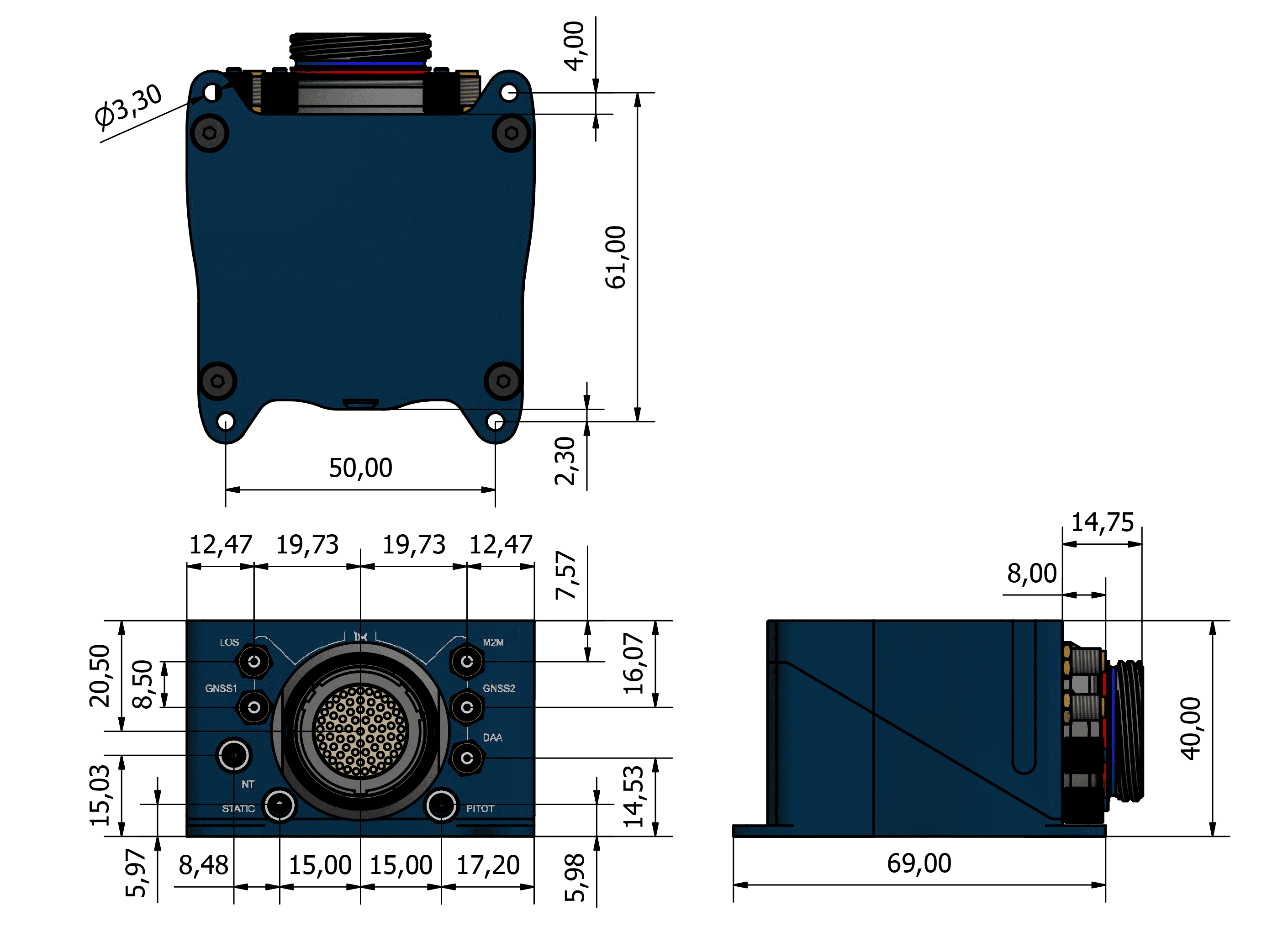
M3 screws are recommended for mounting. In saline environments such as coastal and oceanic, the screw material must be stainless steel.
Interfaces
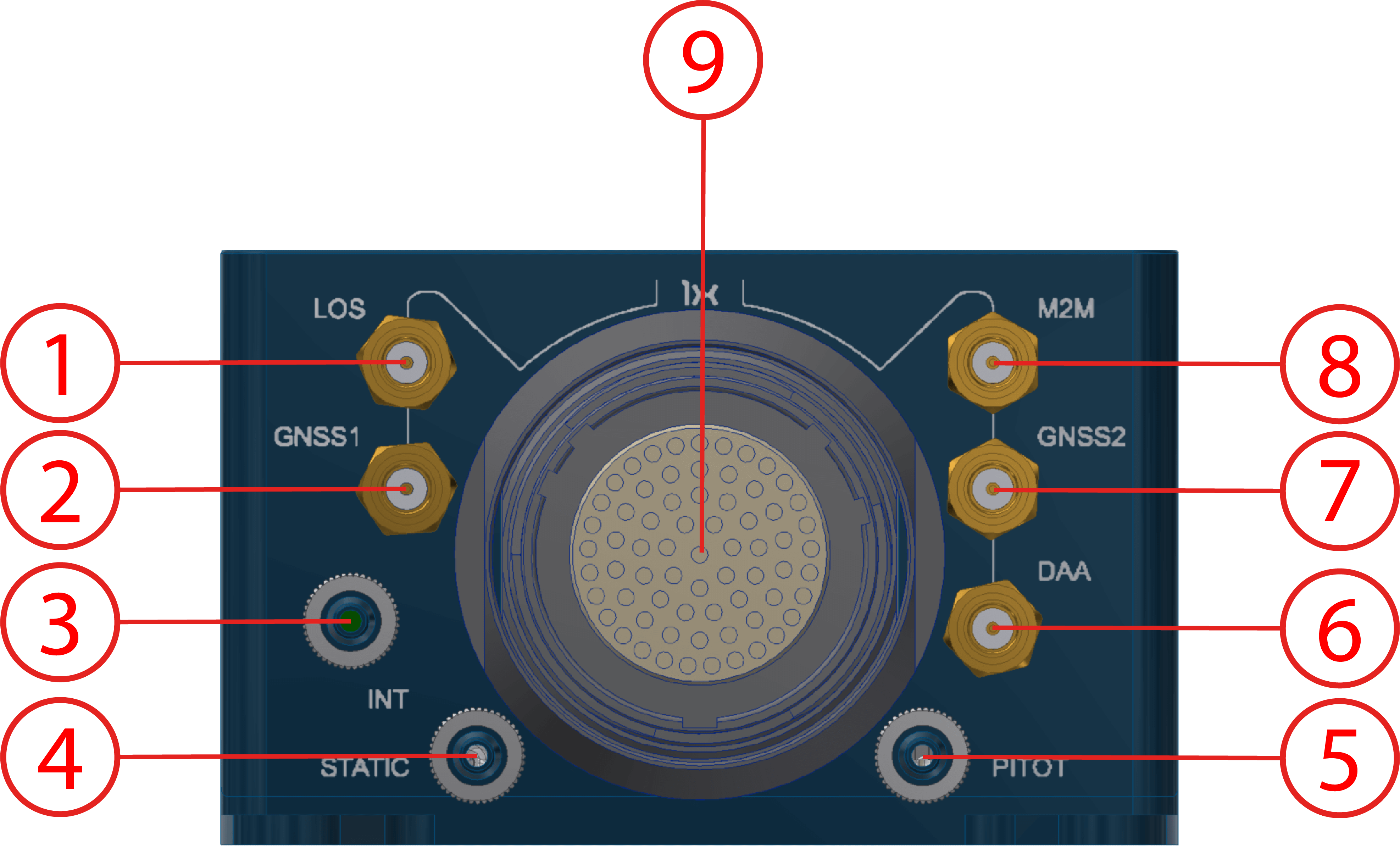
Connector Layout
| Index | Connector |
|---|---|
| 1 | LOS SSMA connector |
| 2 | GNSS1 SSMA connector |
| 3 | Static pressure port (Int. D. 2.5 mm x Out. D. 4 mm) for static pressure sensor 2 |
| 4 | Static pressure port (Int. D. 2.5 mm x Out. D. 4 mm) for static pressure sensor 1 |
| 5 | Dynamic pressure port (Int. D. 2.5 mm x Out. D. 4 mm) |
| 6 |
ADS-B or remote ID SSMA connector
Warning
When using ADS-B or remote ID, there must be an adequate antenna or load connection to the DAA SMA. |
| 7 | GNSS2 SSMA connector |
| 8 |
M2M SSMA connector
Warning
If the BLOS module is enabled, a suitable antenna must be connected to this SSMA port. The 4G Antenna with the Embention reference P000112 is recommended. |
| 9 | 68-pin connector |
Both static pressure ports must be used for sensor redundancy (Y tubing connection is strongly recommended).
Warning
The static pressure port 4 is always used by Autopilot 1x to calculate speed (using the difference of pressure between ports 4 and 5), no matter which sensor is selected in configuration.
Mating Connectors
| Index | Autopilot 1x Connector | Mating Connector |
|---|---|---|
| 1 | RF antenna (SSMA Jack Female) | SSMA male Plug, low-loss cable is recommended. |
| 2, 7 | GNSS antenna (SSMA Jack Female) | SSMA male Plug, low-loss cable is recommended. Active Antenna GNSS:
|
| 8 | M2M antenna (SSMA Jack Female) | SSMA male Plug, low-loss cable is recommended. |
| 6 | ADS-B or remote ID (SSMA Jack Female) | SSMA male Plug, low-loss cable is recommended. |
| 9 | Connector HEW.LM.368.XLNP |
Mating connector: FGW.LM.368.XLCT (Embention reference P005550) Mating harnesses available on demand:
|
© 2025 Embention. All rights reserved.