IMUs & Compass
IMUs
Vectornav VN-300
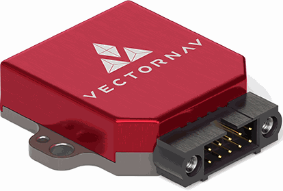
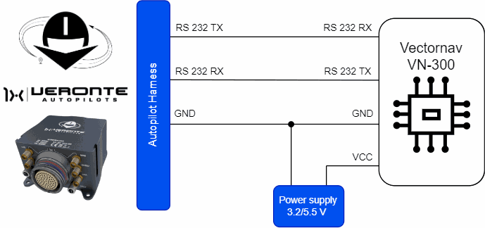
Vectornav VN-300 is an external IMU that can be connected via RS-232 (serial interface) to Veronte Autopilot 1x.
Important
Note that it must be connected to an external power supply, sharing signal ground with Autopilot 1x.
| Autopilot 1x Harness | VectorNav VN-300 Connector | |||
|---|---|---|---|---|
| PIN | Signal | Color Code | PIN | Signal |
| 19 | RS 232 TX | White-Pink | 1 | RX1 |
| 20 | RS 232 RX | Pink-Brown | 2 | TX1 |
| 21 | GND | White-Blue | 5 | GND |
Warning
Remember!! In Autopilot 1x, all GND pins are common. Note that pin 54 is not a common GND pin.
Once the IMU is connected, the user must proceed to its software integration with Veronte Autopilot 1x by referring to the Vectornav VN-300 - Integration examples of the 1x PDI Builder user manual.
WitMotion HWT905-232
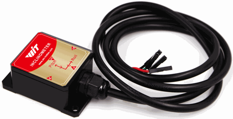
Vectornav VN-300 is an external IMU that can be connected via RS-232 (serial interface) to Veronte Autopilot 1x.

Important
Note that it must be connected to an external power supply, sharing signal ground with Autopilot 1x.
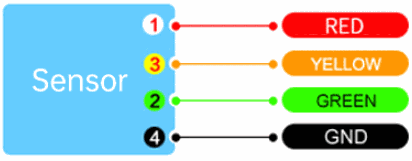
| Autopilot 1x Harness | WitMotion HWT905-232 Connector | ||||
|---|---|---|---|---|---|
| PIN | Signal | Color Code | PIN | Signal | Color Code |
| 19 | RS 232 TX | White-Pink | 2 | RX | Green |
| 20 | RS 232 RX | Pink-Brown | 3 | TX | Yellow |
| 21 | GND | White-Blue | 4 | GND | Black |
Warning
Remember!! In Autopilot 1x, all GND pins are common. Note that pin 54 is not a common GND pin.
Once the IMU is connected, the user must proceed to its software integration with Veronte Autopilot 1x by referring to the WitMotion HWT905-232 - Integration examples of the 1x PDI Builder user manual.
Magnetometers
Magnetometer Honeywell HMR2300
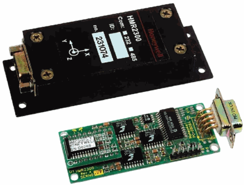
Magnetometer Honeywell HMR2300 is an external magnetometer that can be connected to Veronte Autopilot 1x via RS232 or RS485 (serial interfaces).
Connections via RS232 and RS485 interfaces are explained separately.
RS232
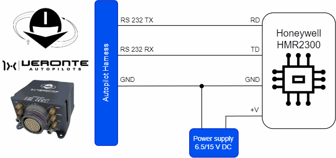
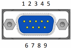
For proper operation via RS232, the connection between Magnetometer Honeywell HMR2300 and Autopilot 1x pins should be like this:
| Autopilot 1x Harness | Magnetometer Honeywell HMR2300 Connector | |||
|---|---|---|---|---|
| PIN | Signal | Color Code | PIN | Signal |
| 19 | RS 232 TX | White-Pink | 3 | RD |
| 20 | RS 232 RX | Pink-Brown | 2 | TD |
| 21 | GND | White-Blue | 5 | GND |
Warning
Remember!! In Autopilot 1x, all GND pins are common. Note that pin 54 is not a common GND pin.
Once the Magnetometer Honeywell HMR2300 is connected, the user must proceed to its software installation with Veronte Autopilot 1x by referring to the Magnetometer Honeywell HMR2300 (RS232) - Integration examples of the 1x PDI Builder user manual.
RS485
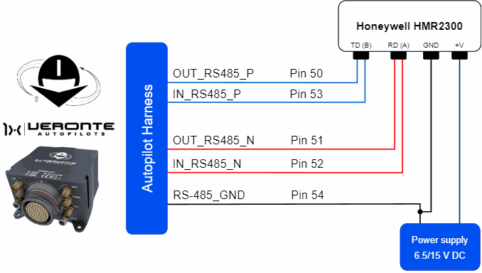
For proper operation via RS485, the connection between Magnetometer Honeywell HMR2300 and Autopilot 1x pins should be like this:
| Autopilot 1x Harness | Magnetometer Honeywell HMR2300 Connector | |||
|---|---|---|---|---|
| PIN | Signal | Color Code | PIN | Signal |
| 50 | OUT_RS485_P | Pink-Brown | 2 | TD (B) Transmit Data, RS-485 (B+) |
| 53 | IN_RS485_P | White-Red | ||
| 51 | OUT_RS485_N | White-Blue | 3 | RD (A) Receive Data, RS-485 (A-) |
| 52 | IN_RS485_N | Brown-Blue | ||
| 54 | OUT_GND | Brown-Red | 5 | GND |
Warning
Note that this pin 54 is not a common GND pin.
Note
If users encounter any problems during wiring, please check the Half-duplex servo does not respond - Troubleshooting section of this manual.
Once the Magnetometer Honeywell HMR2300 is connected, the user must proceed to its software installation with Veronte Autopilot 1x by referring to the Magnetometer Honeywell HMR2300 (RS485) - Integration examples of the 1x PDI Builder user manual.
MEX as Magnetometer Honeywell HMR2300
MEX can be used as an external magnetometer Honeywell HMR2300 connected to Veronte Autopilot 1x via serial (RS232/RS485) or CAN interfaces.
Connections via CAN, RS232 and RS485 interfaces are explained separately.
CAN
For proper operation via CAN, the connection between MEX and Autopilot 1x pins should be like this:
| Autopilot 1x Harness | MEX Connector | |||
|---|---|---|---|---|
| PIN | Signal | Color Code | PIN | Signal |
| 25 | CANA_P | White-Black | 22 | CAN A (P) |
| 26 | CANA_N | Brown-Black | 23 | CAN A (N) |
| 28 | CANB_P | Yellow-Green | 20 | CAN B (P) |
| 29 | CANB_N | Pink-Green | 21 | CAN B (N) |
| 30 | GND | Yellow-Pink | 24 | CAN GND |
Note
If only CAN A or CAN B has been configured in the software for communications, only the corresponding pins must be connected.
For more information on CAN connection, please visit CAN - Wiring connection section of this manual.
Warning
Remember!! In Autopilot 1x, all GND pins are common. Note that pin 54 is not a common GND pin.
Important
Integration is also possible by connecting CAN A of the Autopilot 1x to CAN B of the MEX and vice versa, i.e. it does not necessarily have to be CAN A-CAN A or CAN B-CAN B.
However, any connections made must be consistent with the configuration made at software level in 1x PDI Builder and MEX PDI Builder.
RS232
For proper operation via RS232, the connection between MEX and Autopilot 1x pins should be like this:
| Autopilot 1x Harness | MEX Connector | |||
|---|---|---|---|---|
| PIN | Signal | Color Code | PIN | Signal |
| 19 | RS 232 TX | White-Pink | 16 | RS-232 (A) RX |
| 19 | RS-232 (B) RX | |||
| 20 | RS 232 RX | Pink-Brown | 15 | RS-232 (A) TX |
| 18 | RS-232 (B) TX | |||
| 21 | GND | White-Blue | 17 | GND |
Warning
Remember!! In Autopilot 1x, all GND pins are common. Note that pin 54 is not a common GND pin.
Important
Integration is possible by connecting the RS-232(A) or RS-232(B) from MEX to the RS232 of Autopilot 1x.
However, any connections made must be consistent with the configuration made at software level in 1x PDI Builder and MEX PDI Builder.
RS485
For proper operation via RS485, the connection between MEX and Autopilot 1x pins should be like this:
| Autopilot 1x Harness | MEX Connector | |||
|---|---|---|---|---|
| PIN | Signal | Color Code | PIN | Signal |
| 50 | OUT RS485_P | Pink-Brown | 33 | IN RS-485 (P) |
| 51 | OUT RS485_N | White-Blue | 31 | IN RS-485 (N) |
| 52 | IN RS485_N | Brown-Blue | 32 | OUT RS-485 (N) |
| 53 | IN RS485_P | White-Red | 30 | OUT RS-485 (P) |
| 54 | OUT_GND | Brown-Red | 34 | RS-485 GND |
Warning
Note that, in Autopilot 1x, this pin 54 is not a common GND pin.
Important
Any connections made must be consistent with the configuration made at software level in 1x PDI Builder and MEX PDI Builder.
PNI RM3100
PNI RM3100-CB magnetometer must be connected to Autopilot 1x via I2C.
Important
This integration example is described for the RM3100-CB.
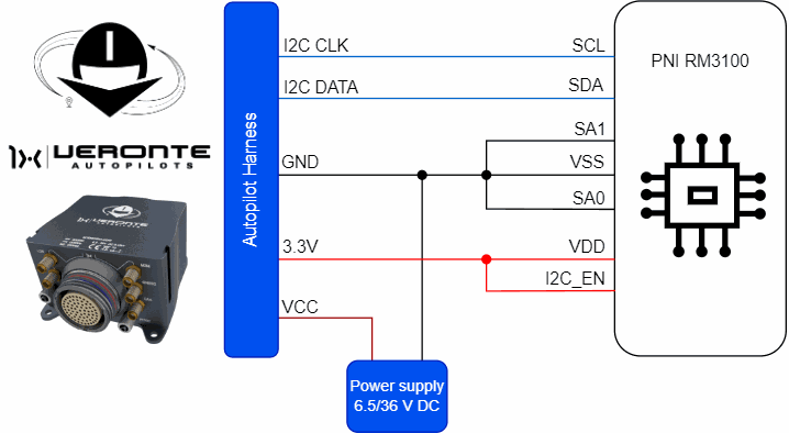
| Autopilot 1x Harness | PNI RM3100-CB Connector | |||
|---|---|---|---|---|
| PIN | Signal | Color Code | PIN | Signal |
| 31 | I2C_CLK | White | 1 | SCL |
| 32 | I2C_DATA | Brown | 3 | SDA |
| 33 | GND | Green | 4 | VSS Ground |
| 2 | SA1 Bit 1 of slave address |
|||
| 7 | SA0 Bit 0 of slave address |
|||
| 34 | 3.3V | Yellow | 8 | VDD Supply Voltage |
| 5 | I2C_EN I2C enable pin (HIGH = I2C) |
|||
Warning
Remember!! In Autopilot 1x, all GND pins are common. Note that pin 54 is not a common GND pin.
Once the magnetometer is connected, the user must proceed to its software integration with Veronte Autopilot 1x by referring to the PNI RM3100 - Integration examples section of the 1x PDI Builder user manual.
© 2025 Embention. All rights reserved.