Actuators
Actuators tab displays the Actuator blocks as created and configured in Block Programs of 1x PDI Builder app.
This menu allows the calibration of all the connected actuators that control the attitude of the aircraft. It is possible to set actuator position for each control signal/output, allowing to configure the maximum and minimum values and its custom performance.
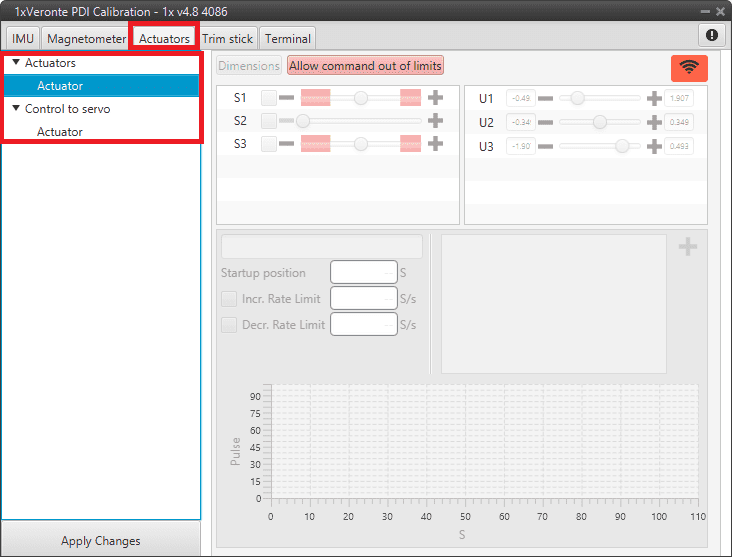
Actuators Calibration menu
The options of this calibration menu are presented below:
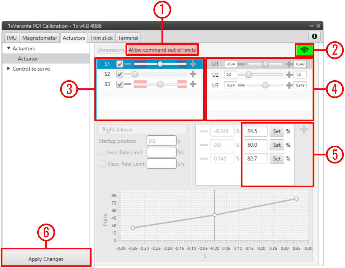
Actuators Calibration parameters
Important
Only the parameters that can be modified in this menu are explained. Therefore, those that are disabled, cannot be modified here, this is because they must be configured in the corresponding Actuator block of the 1x PDI Builder software.
Allow command out of limits: Allows out-of-limits motion for the selected actuator.
Tip
When the user is in the trimming process, it is possible that the desired servo position is in the Out of range zone (red zone), so by pressing this button it is possible to move the actuator completely and find the correct position.
Enable/Disable command: Enables/Disables commands to move the servos. It is enabled when the icon is green and disabled when it is red.
Servos (actuators): This menu contains the servos of the aircraft.
Moving the scrolling bar will change the servo position, but the signal to the system will only be sent if the checkbox next to the servo number (S1, S2, …) is marked.
Error
The manual movement of the servos can only be performed in the “Initial” phase (when there is no phase selected in the Veronte Panel of Veronte Ops).
Control Signals: This menu contains the variables representing the control signals/outputs \(U\) generated by the system. Control outputs are not predeterminated, they depend on \(SU\) matrix configuration. For more information regarding \(U\) control outputs, please refer to the Actuator - Servos blocks of Block Programs section in the 1x PDI Builder user manual.
Considering that the above example is for a flying wing, the controls are pitching (U1), thrusting (U2) and rolling (U3), so there are 3 different controls in total. When moving the scroll bar of one of the control channels, the corresponding movement in the servos will also be represented.
Servo Position - PWM: This option is used to set the transformation from a control position \(S\) to PWM signal.
Note
Notice that the desired control position \(S\) needs to be clicked on in order to interact with this section. Once a control position is selected, only the PWM percentage can be changed.
For example, in the figure above, a 20º degrees deflection (0.349 rad) of the right aileron corresponds to an 82.7% pulse to be sent to the corresponding servo.
For more information on the PWM percentage, refer to the PWM - Connections section of the 1x PDI Builder user manual.
Apply Changes: After making the necessary customizations, the user should click on this button to save the changes.
As this action will restart the device, the following confirmation messages will appear when clicked:
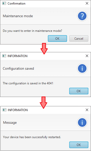
Actuators Calibration - Apply Changes confirmation messages
Trimming
Trimming can be performed by moving the servos in three different positions: zero position, minimum and maximum deflection angle (angles are usually physically limited). These positions must be entered and saved in the software by clicking on ‘Apply Changes’ when the actuator is in the desired position. Otherwise, the position can be entered manually.
The figure above shows the setting of the right aileron:
Minimum: -0.349 [rad] deflection \(\Rightarrow\) 24.5% PWM output.
Zero position: 0 [rad] deflection \(\Rightarrow\) 50% PWM output.
Maximum: 0.349 [rad] deflection \(\Rightarrow\) 82.7% PWM output.