Integration examples
In this section, a series of examples will be presented so that the user knows how to perform certain customizations in the 1x PDI Builder. In addition, some examples of integration between the Autopilot 1x and external devices are presented.
AP communication with PC
Since Veronte Autopilot 1x can be connected to a computer via a USB or serial interface, the configuration for both connections is already set by default in 1x PDI Builder.
However, users should check that this configuration has not been modified to ensure a correct communication via both ways in case one of them is lost. For this:
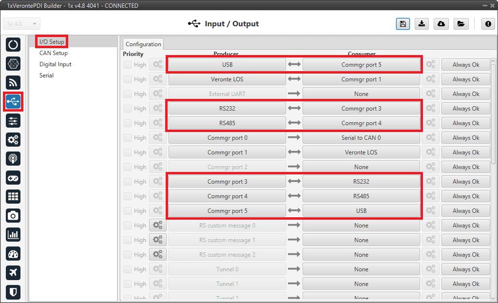
Go to Input/Output menu I/O Setup panel. Each USB, RS232 and RS485 Producers must be bidirectionally connected to a Commgr port:
Important
Users should also check that the Commgr ports to which USB and serial ports are connected are not routed. For more information on Routing, see Ports - Communications section of this manual.
ArcTrim Button
The ArcTrim button allows the user to trim the stick signal directly from the stick position, before the operation, by simply clicking on it. In addition, this button is considered as an 'action button' that can be embedded in the Veronte Panel.
To do this, the following steps should be followed:
-
Go to Block Programs menu.
-
Create a program to make the necessary connection to the Arc Trim block.
Usually the user has a Stick program where the blocks that are related to the stick are implemented.
-
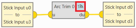
Add the Arc Trim block and connect the input and output variables to it.
Usually the input variables are Stick Input u0-u3 and the output variables Stick Input d0-d3.
-
Finally, enable the block to be commandeded by simply clicking on the
 icon.
icon.
ArcTrim Button - Block -
-
Configure the trim vector of the Arc Trim block.
Depending on the range of the signal, the following values are recommended:
- If the signal ranges from 0 to 1 0.5.
- If the signal ranges from -1 to 1 0.
In this example, since the signal is in the range 0-1, 0.5 is set:
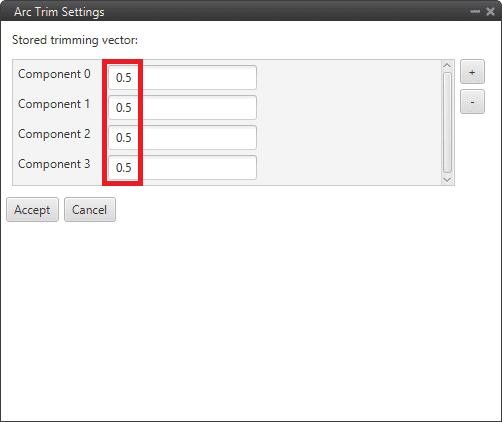
ArcTrim Button - Block configuration -
Go to Automations menu create a New automation go to Events.
Select the Button option and choose the desired icon for this button.
In addition, it is recommended to activate the Confirmation checkbox, to avoid trimming the stick by mistake.
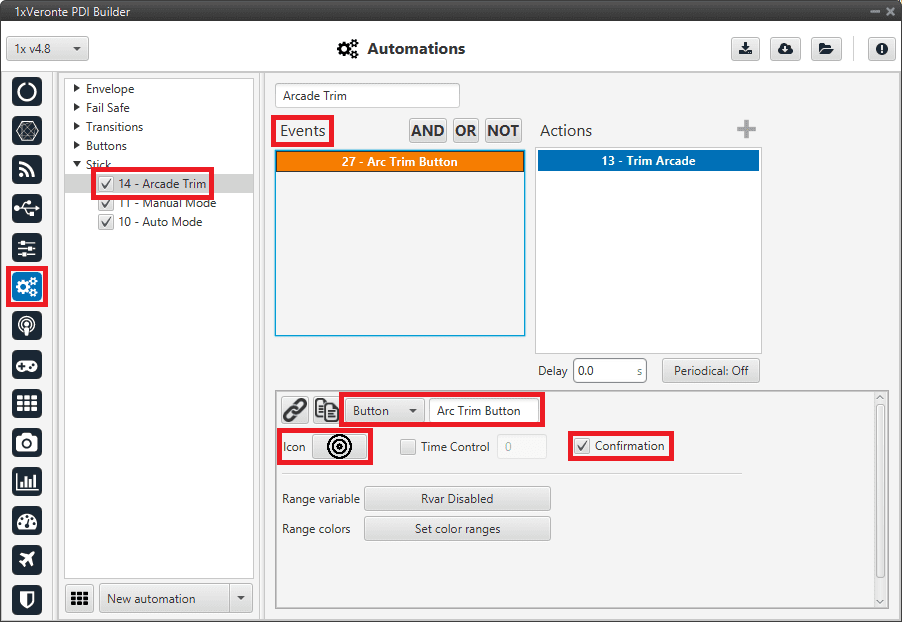
ArcTrim Button - Events -
In the created automation, go to Actions.
- Add the Command block action.
- Select ArcTrim block to command and choose the commandable Id.
- Finally, it is recommended to activate both checkboxes:
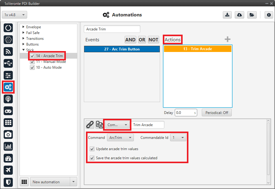
ArcTrim Button - Actions -
In Veronte Ops, this button will appear embedded in the Veronte Panel.
Note
This action button will only appear on the Veronte Panel if the action buttons have been enabled to be shown on it. For more information on this, see Veronte Panel - Main widgets section on the Veronte Ops user manual.
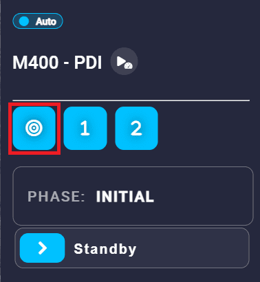
ArcTrim Button - Veronte Panel When clicking on it, the following confirmation message will be displayed (as the confirmation checkbox has been activated in the automation):

ArcTrim Button - Confirmation message Now, the stick is trimmed.
CAN communication
Here are described the steps to be followed in order to correctly receive and transmit CAN messages, both via CAN and serial interfaces.
CAN messages transmission
This section summarizes the configuration to be carried out to send CAN streams over a CAN bus.
-
Go to Input/Output menu CAN Setup panel Custom message 0 tab.
Select the fields to send in TX or TX Ini, as it is a Producer.
More information on the configuration of CAN messages can be found in the TX/TX Ini Messages (Custom Messages) - Input/Output section of this manual.
For example, a CAN message set to ID 12:

CAN messages transmission - Custom message configuration -
Go to Input/Output menu CAN Setup panel Configuration tab.
Connect CAN custom message 0 producer (as the message has been configured in the Custom Message 0 tab) to an Output filter as follows:
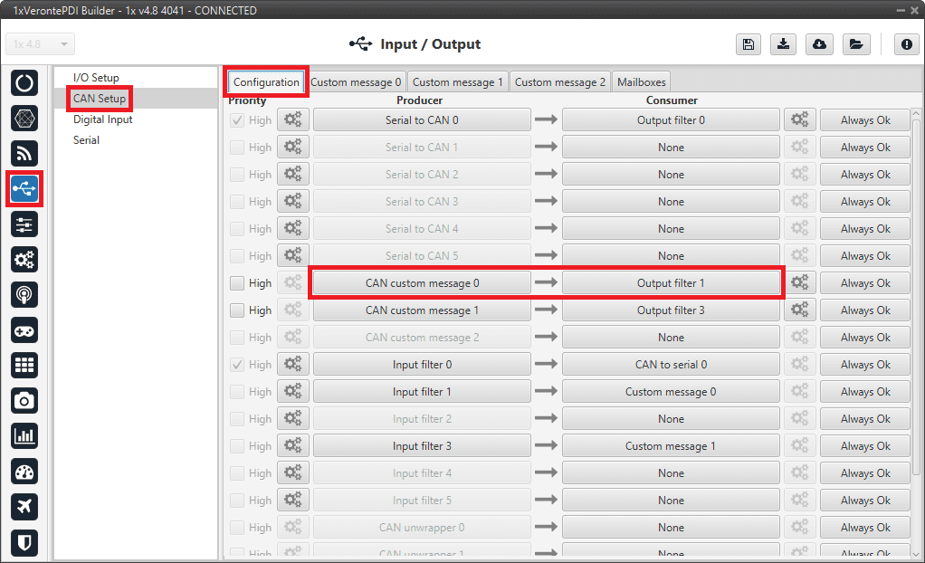
CAN messages transmission - CAN Setup configuration
Warning
Remember that it is necessary to have at least 1 free mailbox for TX messages.
CAN messages reception
This section summarizes the configuration to be carried out to receive CAN streams over a CAN bus.

-
Go to Input/Output menu CAN Setup panel Mailboxes tab.
Configure the mailbox to receive a message with the appropiate ID (in this example ID 28 has been configured):
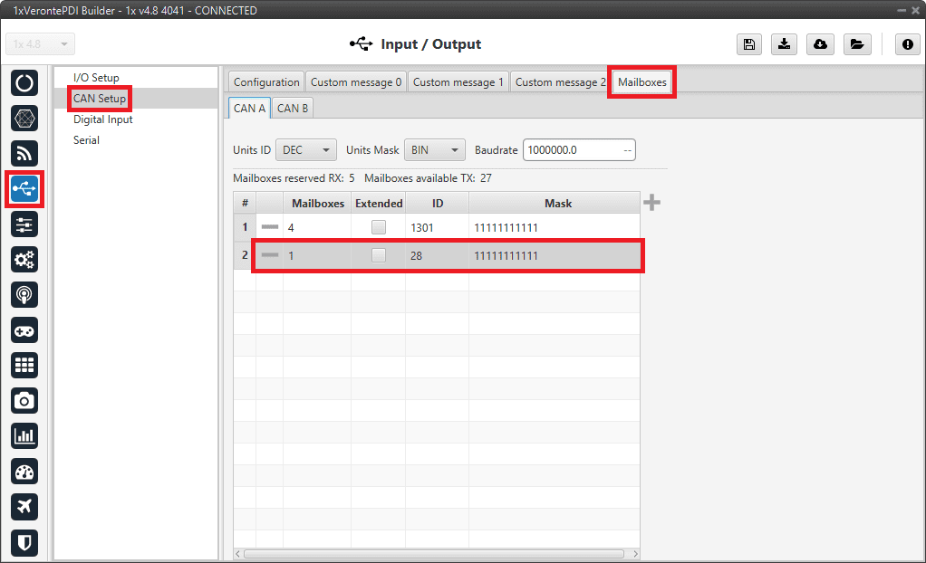
CAN messages reception - Mailboxes configuration -
Go to Input/Output menu CAN Setup panel Configuration tab.
Connect an Input filter with the right CAN ID to a Custom message consumer:
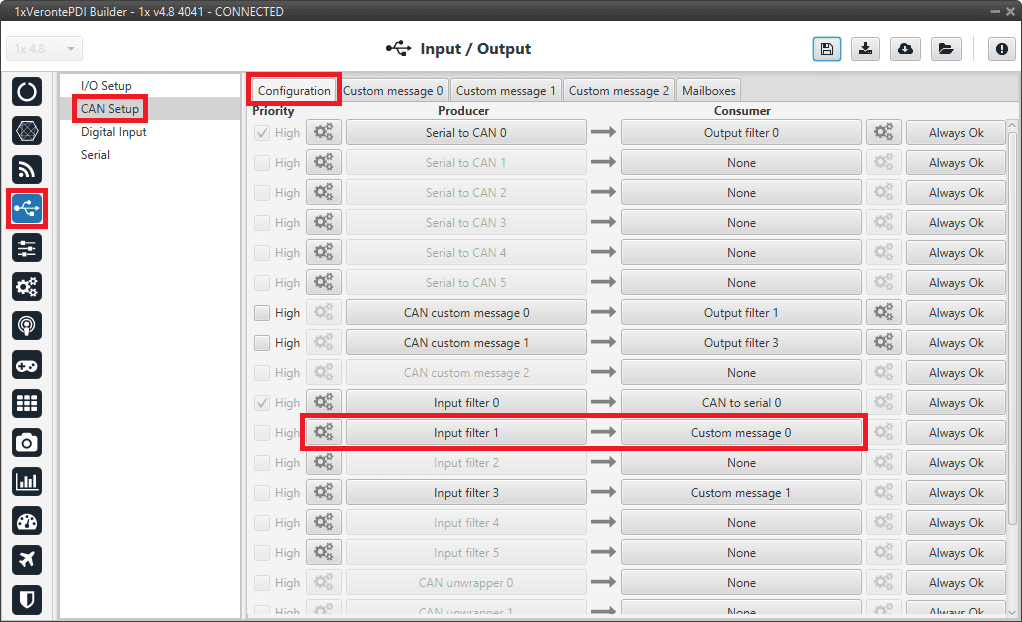
CAN messages reception - CAN Setup configuration 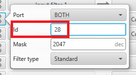
CAN messages reception - Input filter configuration -
Go to Input/Output menu CAN Setup panel Custom message 0 tab (as Custom Message 0 has been selected as consumer).
Configure the message reading as desired in RX by setting the correct CAN ID.
The different options and parameters to be configured are explained in the RX Messages (Custom Messages) - Input/Output section of this manual.
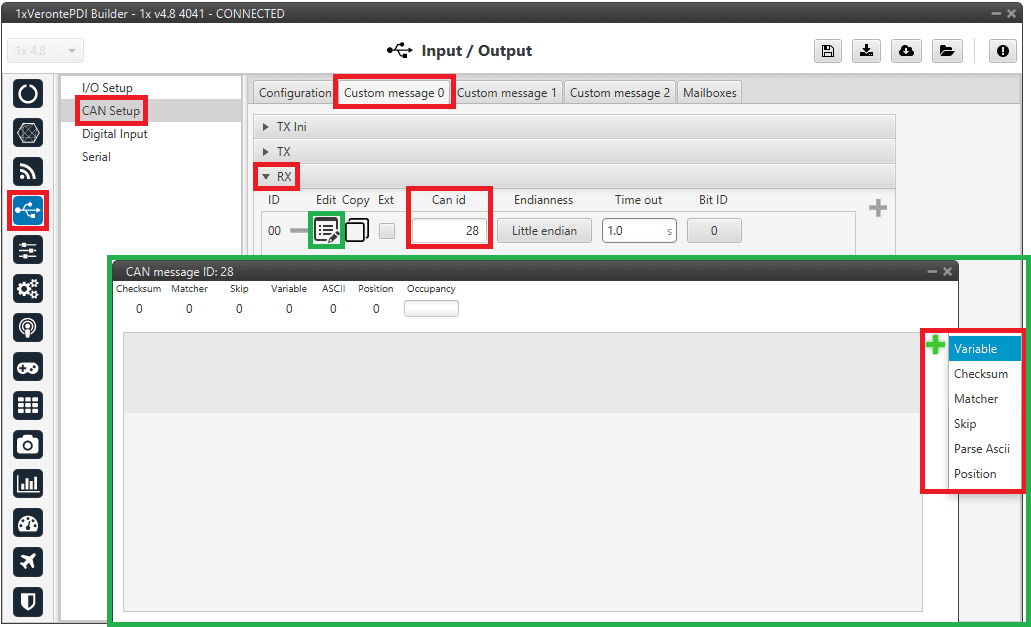
CAN messages reception - Custom message configuration
CAN messages transmission via serial
This section summarizes the configuration to be carried out to send CAN streams over a serial bus.
Note
For sending CAN streams over a serial bus, a CAN wrapper port is needed. For further details of this port, please consult the CAN wrapper/CAN unwrapper - I/O Setup section of the present manual.
-
Go to Input/Output menu CAN Setup panel Custom message 0 tab.
Important
The index of the Custom message tab must match the index of the CAN custom message producer to configure. In this example, tab 0 is selected.
Select the fields to send in TX or TX Ini, as it is for transmission.
More information on the configuration of CAN messages can be found in the TX/TX Ini Messages (Custom Messages) - Input/Output section of this manual.
For example, a CAN message set to ID 12:
CAN messages transmission via serial - Custom message configuration -
Go to Input/Output menu CAN Setup panel Configuration tab.
Connect CAN custom message 0 producer (as the message has been configured in the Custom message 0 tab) to a CAN wrapper consumer as follows:
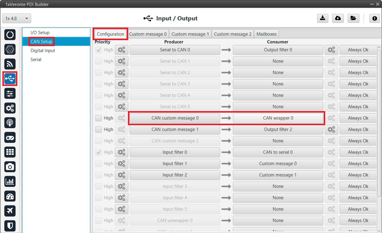
CAN messages transmission via serial - CAN Setup configuration -
Go to Input/Output menu I/O Setup panel.
Connect the CAN wrapper 0 producer to a RS232 or RS485 consumer as shown below.
Important
The index of the CAN wrapper producer must match the index of the CAN wrapper consumer configured in the previous step.
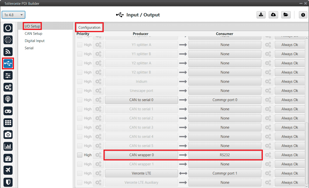
CAN messages transmission via serial - I/O Setup configuration
Warning
Remember that it is necessary to have at least 1 free mailbox for TX messages.
CAN messages reception via serial
This section summarizes the configuration to be carried out to receive CAN streams over a serial bus.
Note
For receiving CAN streams over a serial bus, a CAN unwrapper port is needed. For further details of this port, please consult the CAN wrapper/CAN unwrapper - I/O Setup section of the present manual.

-
Go to Input/Output menu I/O Setup panel.
Connect a RS232/RS485 producer to a CAN unwrapper consumer.
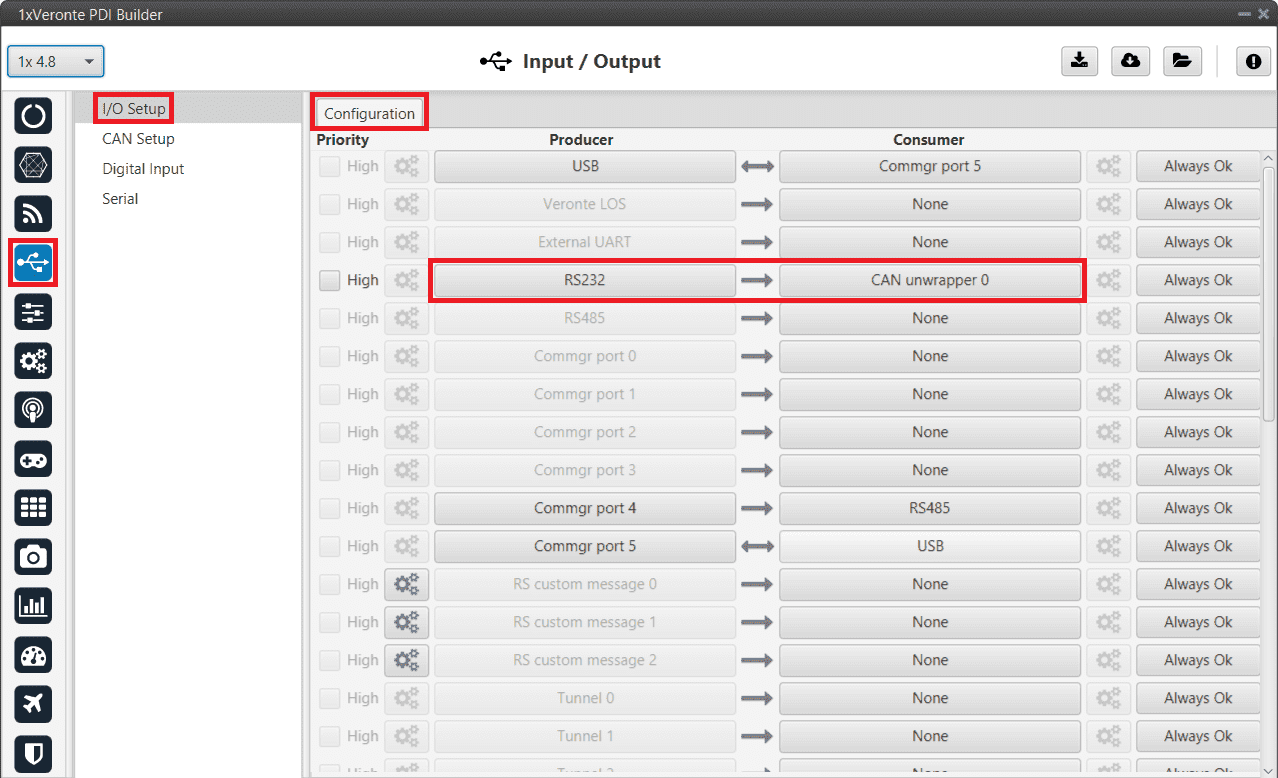
CAN messages reception via serial - I/O Setup configuration -
Go to Input/Output menu CAN Setup panel Mailboxes tab.
Configure the mailbox to receive a message with the appropiate ID (in this example ID 28 has been configured):
CAN messages reception via serial - Mailboxes configuration -
Go to Input/Output menu CAN Setup panel Configuration tab.
Connect a CAN unwrapper producer to a Custom message consumer. In this example, Custom message 0 consumer is selected.
Important
The index of the CAN unwrapper producer must match the index of the CAN unwrapper consumer configured in the previous step.
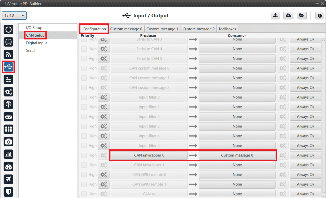
CAN messages reception via serial - CAN Setup configuration -
Go to Input/Output menu CAN Setup panel Custom message 0 tab.
Important
The index of the Custom message tab must match the index of the Custom message consumer to configure. In this example, tab 0 is selected.
Configure the message reading as desired in RX by setting the correct CAN ID.
The different options and parameters to be configured are explained in the RX Messages (Custom Messages) - Input/Output section of this manual.
CAN messages reception via serial - Custom message configuration
Communication between Veronte Autopilots 1x
To establish a proper communication between the ground and air units, it is necessary to configure the ports menu of the ground unit.
- Go to Communications menu Ports panel (for more information about this, see Ports - Communications section of this manual).
- Set a routing of Address 2 (address by which Autopilots 1x ground and air units communicates with all Veronte applications) through the port to which the USB is connected (to allow connection to the PC), in this case it is PORT 0.
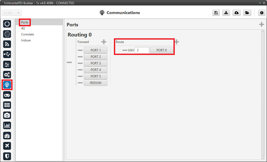
This way, any messages that are received through a Commgr Port (i.e. through Veronte LOS) with Address 2, will be re-routed through Port 0 (USB) and received by Veronte Link/Ops software, including any messages generated by 1x ground unit itself.
The following diagram summarizes the connection:

Caution
If routing of Address 2 is not configured on the Ground unit, VCP messages arriving to it with a Source other than its own (in this case the source is the Air unit) will be ignored.
Data transmission between Veronte Autopilots 1x
To enable the data transmission between the ground and air units, the telemetry and sniffer menus must be configured, respectively.
A simple example of use between a ground unit and an air unit is shown below:
In the 1x ground unit:
- Go to Telemetry menu Telemetry panel Data link to VApp tab (for more information about this, see Data vectors - Telemetry section of this manual).
- Add the variables: Absolute: UAV position, Yaw, Pitch and Roll.
- Set a Frequency, it is recommended to set it to 10 Hz.
- On Address, point to the 1x air unit (it is needed to have both units connected through the radio in order to be able to see them on the menu).
For the 1x air unit :
- Go to Telemetry menu Sniffer panel (for more information about this, see Sniffer - Telemetry section of this manual).
- Add a new Sniffer.
- Configure the same variables (keeping the same order) than in the ground unit.
- On Address, point to the 1x ground unit.
- In the gear next to it, configure the 4 incoming variables as System Variables: assign UAV Position to Moving Object and the 3 variables from attitude to 3 different User Variables (keeping the same order as well).
Dynamic addresses for telemetry vectors
In cases where users need to use more than one telemetry vector for Veronte data, they would need to send telemetry through dynamic addresses of Veronte applications. Consult the range of the dynamic addresses that can be used in the List of Addresses - Lists of interest section of the 1x Software Manual.
In this example, we will send telemetry through LOS and through SATCOM. For this:
-
Go to Telemetry menu Telemetry panel Data link to VApp tab (for more information about this, see Data vectors - Telemetry section of this manual).
- Change the address to the 255 dynamic address (this can be the dynamic address of the user's choice).
- Add a second data vector by clicking
 and set it to the 256 dynamic address (this can be the dynamic address of the user's choice).
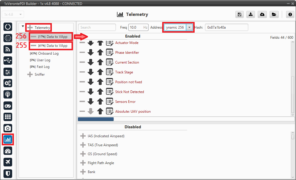
Dynamic addresses for telemetry vectors - Telemetry configuration -
Go to Input/Output menu I/O Setup panel.
- Connect the Veronte LOS producer to a COM manager port consumer, in this example Commgr port 1 is chosen.
- Connect the RS232 producer (since in this example SATCOM is connected via RS232 to Autopilot 1x) to another COM manager port consumer, in this example Commgr port 3 has been selected.
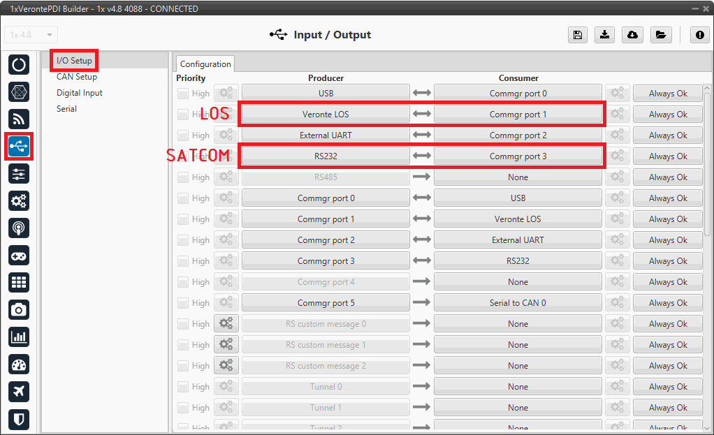
Dynamic addresses for telemetry vectors - I/O Setup configuration -
Go to Communications menu Ports panel.
- Add a routing for the dymamic address previously configured for LOS telemetry, in this case address 255 to PORT 1 (LOS connection).
- Add another routing for the dymamic address previously configured for SATCOM telemetry, in this case address 256 to PORT 3 (SATCOM connection).
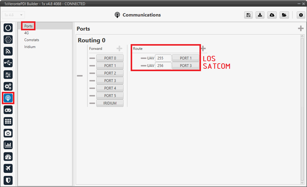
Dynamic addresses for telemetry vectors - Ports configuration
Therefore, with these configurations we get that any message received with address 255 to any COM mananger port, will be redirected to LOS (PORT 1). And, in the same way, we get that any message received with address 256 to any COM manager port, will be redirected to SATCOM (PORT 3).
Important
If you want to send only the telemetry vector (the vector configured with the specific address) through the port, you must also remove the corresponding port from the Forward column. Otherwise, for example in this case, everything will be sent through PORT 1 except the messages with address 256, which will be sent through PORT 3, and vice versa.
Flare and Decrab phase configuration
As flare and decrab guidance are not included in the landing algorithm, since the decrab is control dependent (yaw must be aligned with the runway direction), the following shows how to implement this guidance in a generic fixed wing configuration:
-
First, it can be useful to create a program that computes the altitude above the touchpoint, the lateral error over the desired route and the heading error. If all conditions met, the flare phase is triggered:
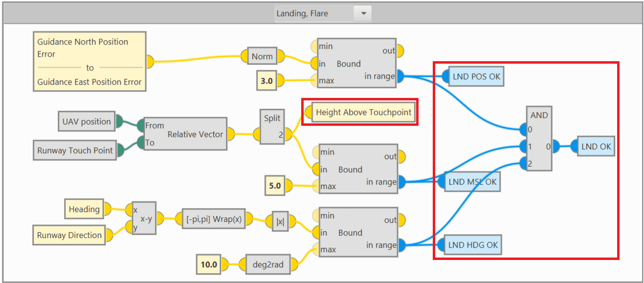
Flare and Decrab phase - Auxiliary program -
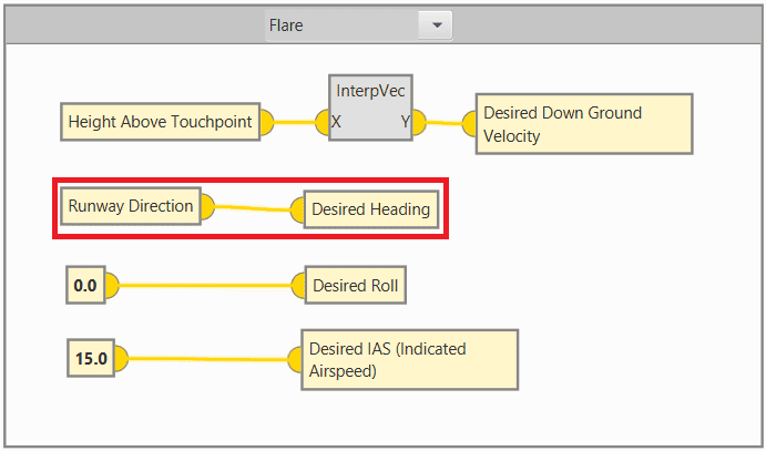
Flare and Decrab guidance definition
In the Guidance program (where the guidances for all phases are defined), add the Flare phase to the Phase Switch block.
Then, the flare and decrab guidance must be built as follows:
-
The desired vertical speed is overwritten to be a function of the height above the runway. In this case the height is calculated in an auxiliary program (Height Above Touchpoint variable calculated in step 1), but the AGL could be used.
-
The desired yaw is overwritten directly by the runway direction.
- The desired roll is overwritten to 0º.
- The desired IAS is overwritten to a speed slightly above the stall speed, in this example 15 m/s.
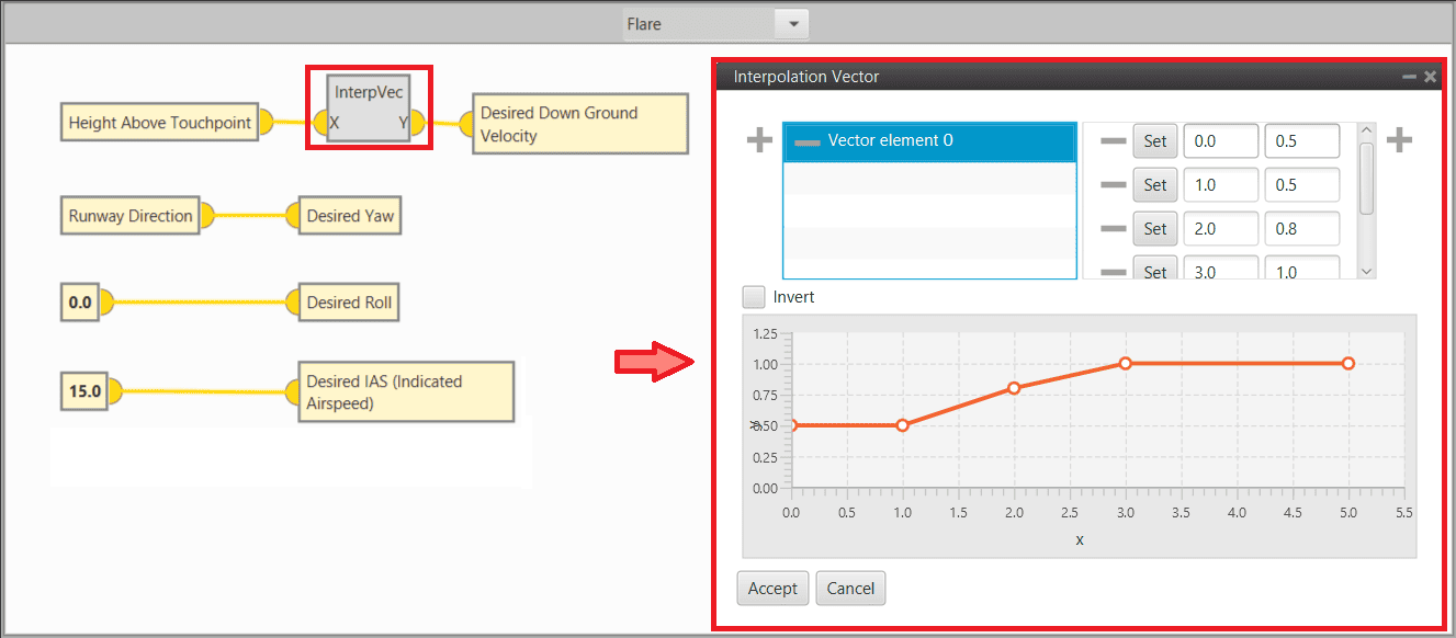
Flare and Decrab phase - Flare and decrab guidance definition -
-
Pitching control
The desired vertical speed is used for pitch control as shown below:
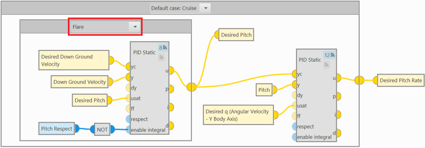
Flare and Decrab phase - Pitching control -
Thrusting control
The throttle is used to maintain the IAS (slightly above stall) and when a height above touchpoint of 1 m is reached, the motor is cut off.
Again, a user variable is used here (Height Above Touchpoint variable calculated in step 1), but the AGL could be used:
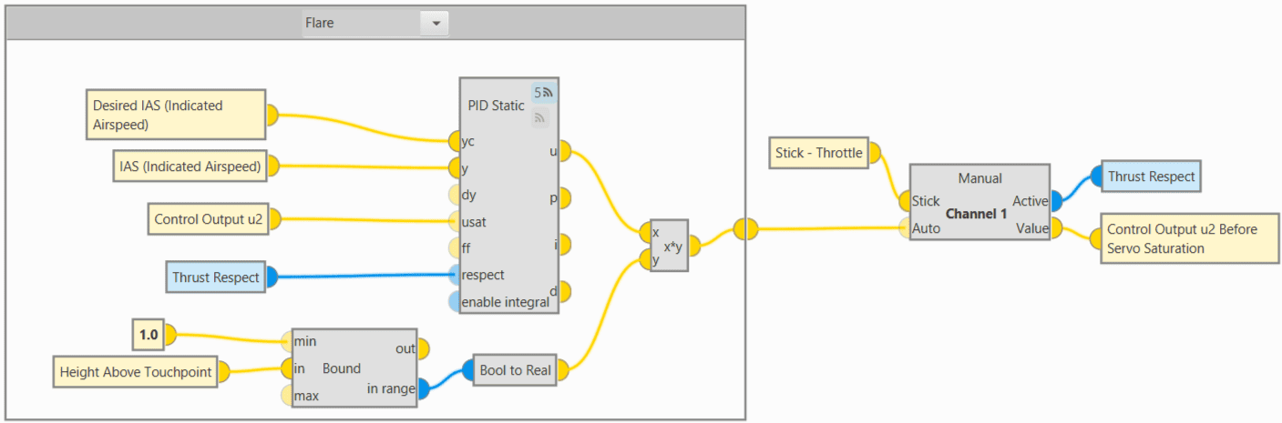
Flare and Decrab phase - Thrusting control -
Rolling control
For the roll, simply try to maintain the desired roll (0º):
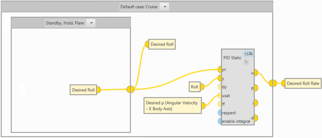
Flare and Decrab phase - Rolling control -
Yawing control
The yaw control (rudder) is based on the desired yaw:
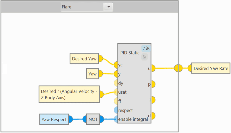
Flare and Decrab phase - Yawing control Important
This algorithm requires a good yaw estimation if users want to have Decrab, so magnetometer or GNSS Compass is required.
Flare phase configuration
However, for a Flare phase without Decrab, the yaw control should be based on heading instead of being based on yaw. To do so, the Guidance and Yawing programs must look as shown below:
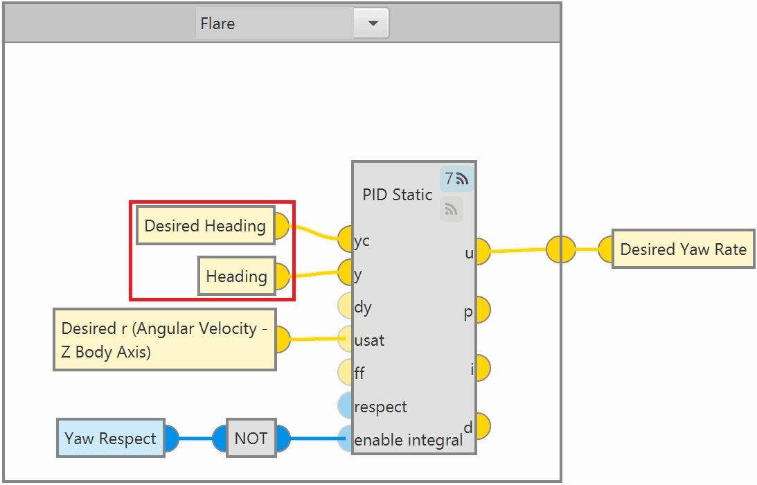
For more information on block programs, please refer to Block Programs section of this manual.
GNSS Compass Configuration
The GNSS Compass configuration is performed through the GNSS sensor block with the help of the RTK Wizard and the GNSS Compass block.
In this case, users must have 2 GNSS sensor blocks, 1 with the "Dynamic Base" configuration (Base) and the other with a "Rover" configuration.
- Open the configuration of one of the GNSS sensor blocks, in this case, this is the configuration for the GNSS1 sensor block.
-
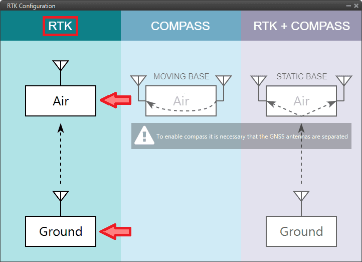
Users must use the RTK Wizard to perfom the corresponding settings:
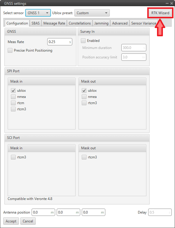
GNSS Compass Configuration - GNSS block -
Click "Air" in the COMPASS column, then choose which will be the Base and which will be the Rover, in this example GNSS1 is set as Rover and GNSS2 is set as Base.
Then, the corresponding Compass configuration will be automatically applied to the users configuration.
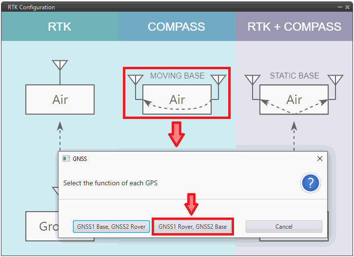
GNSS Compass Configuration - RTK Wizard -
Once the corresponding configurations have been selected, it is necessary to set the following parameters in both GNSS sensor blocks.
First change the Ublox preset parameter to Custom, then:
-
Go to the Configuration tab:
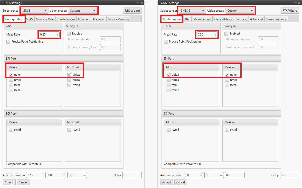
GNSS Compass configuration - Configuration tab configuration - Meas Rate: Recommended value 0.25 s (4 Hz)
- SPI Port: ublox should be checked in Mask in and Mask out
- SCI Port: rtcm3 should be unchecked in Mask in and Mask out
-
In the SBAS tab, leave the configuration as Automatic.
-
Go to the Message Rate tab, it should look as follows:
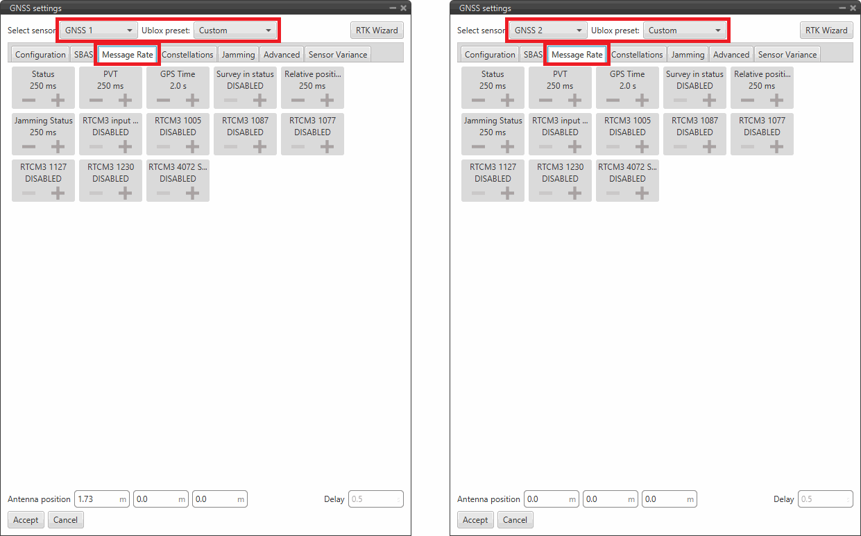
GNSS Compass configuration - Message Rate tab configuration -
Go to the Constellations tab:
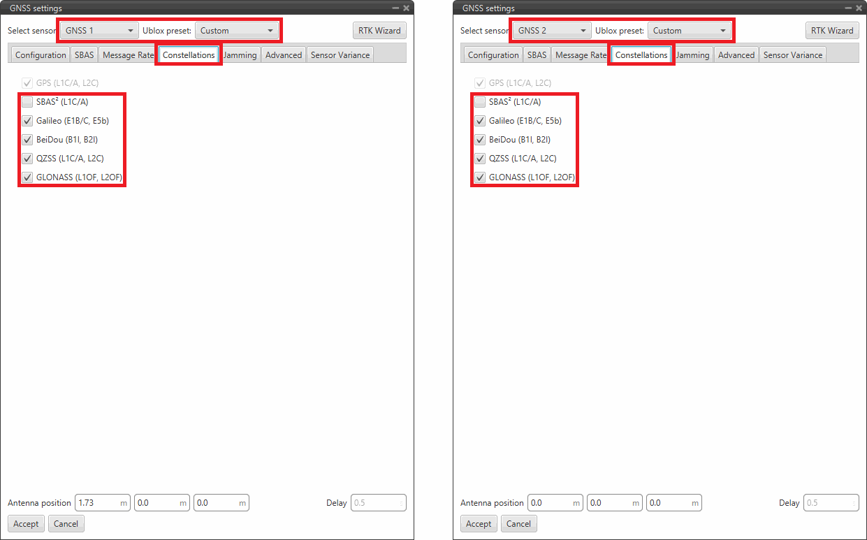
GNSS Compass configuration - Cosntellations tab configuration - (L1C/A): Recommended Disabled
- Galileo (E1B/C, E5b): Recommended Enabled
- BeiDou (B1l, B2l): Recommended Enabled
- QZSS (L1C/A, L2C): Recommended Enabled
- GLONASS (L1OF, L2OF): Recommended Enabled
-
Go to the Jamming tab:
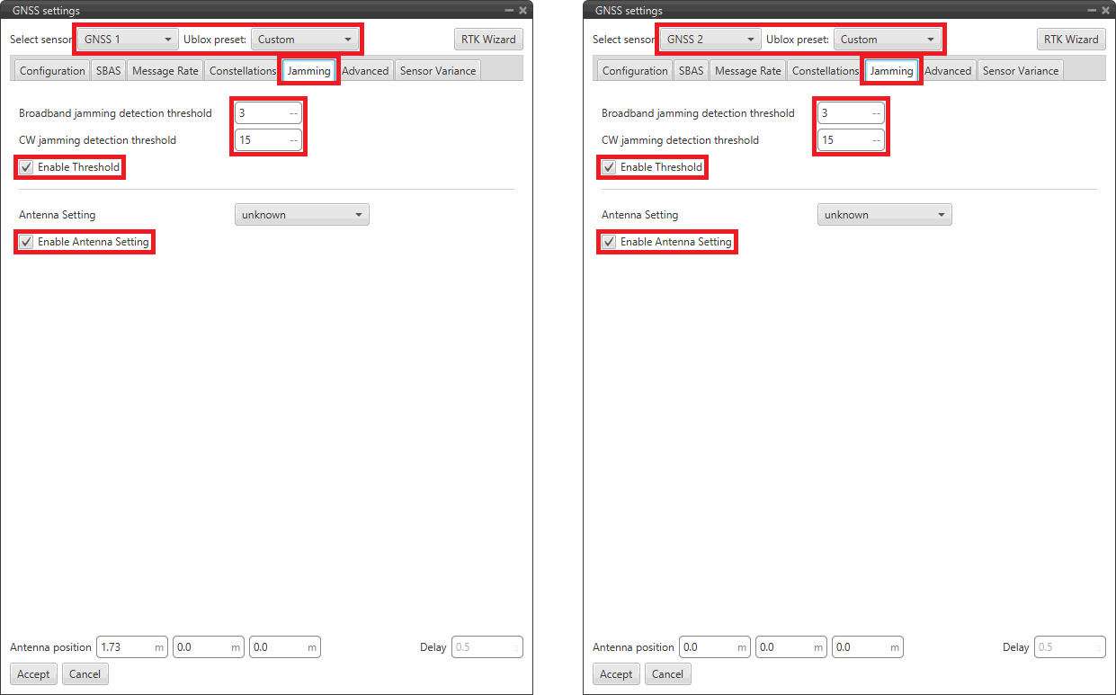
GNSS Compass configuration - Jamming tab configuration - Broadband jamming detection threshold: Recommended value 3
- CW jamming detection threshold: Recommended value 15
- Enable Threshold: Recommended Enabled
- Antenna Setting: unknown
- Enable Antenna Setting: Recommended Enabled
-
Go to the Advanced tab:
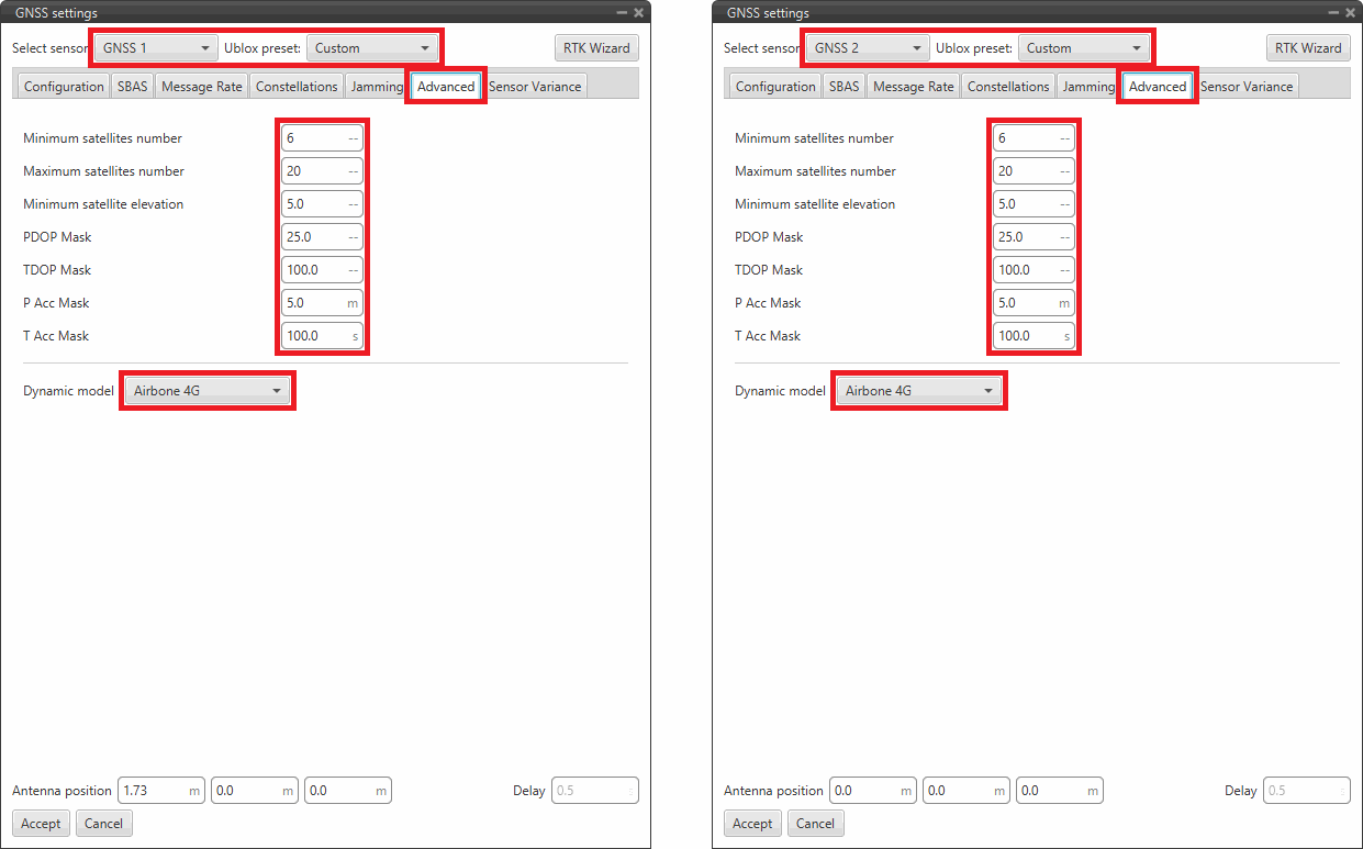
GNSS Compass configuration - Advanced tab configuration - Minimum satellites number: Recommended value 6
- Maximum satellites number: Recommended value 10
- Minimum satellite elevation: Recommended value 5.0
- PDOP mask: Recommended value 25.0
- TDOP mask: Recommended value 100.0
- P Acc mask: Recommended value 5.0 m
- T Acc mask: Recommended value 100.0 s
- Dynamic model: Recommended value Airbone 4G
-
Go to the Sensor Variance tab
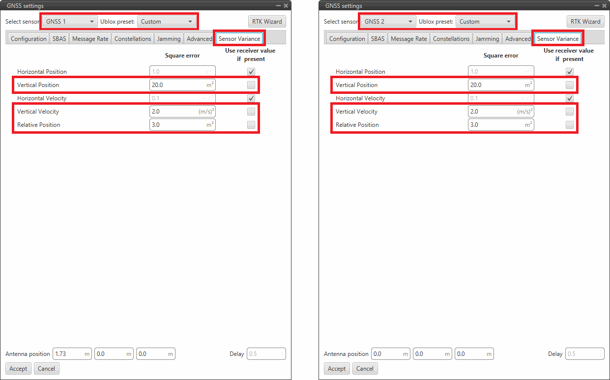
GNSS Compass configuration - Sensor Variance tab configuration - Vertical Position: Recommended value 20.0 .
- Vertical Velocity: Recommended value 2.0 .
-
Relative Position: To enhance the GNSS Compass configuration, if the separation between antennas is given by ,
and the distance between them is calculated as .
Then, this variance must be at most . However, the recommended variance should be set as
Where represents the percentage tolerance, which can be adjusted to be more or less strict but should never exceed 1.
Thus, if the antennas are 2 meters apart, the variance should not exceed 4 and should typically be set between 10% and 30% of this value.
-
-
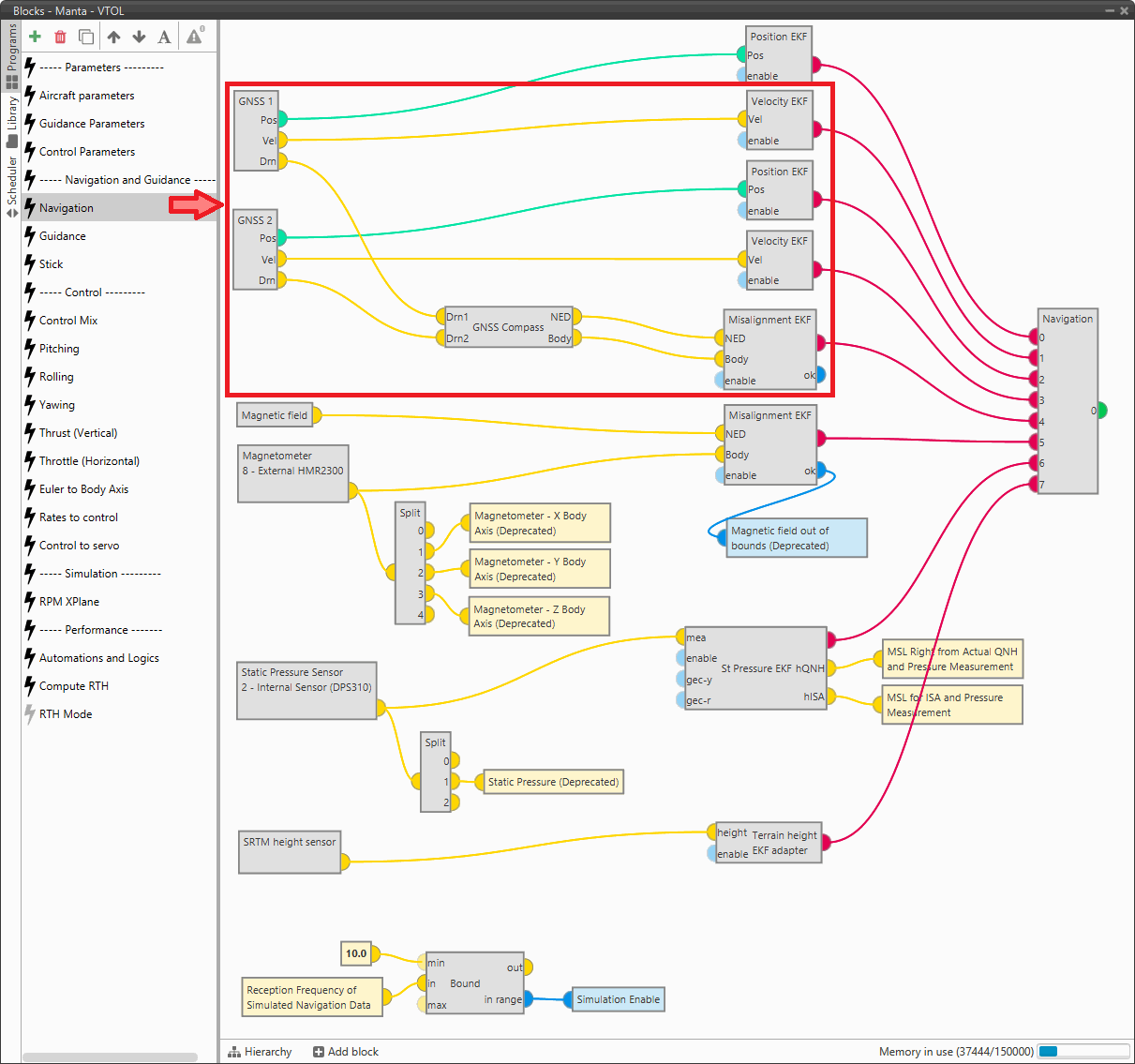
Next, the connection between GNSS1 and GNSS2 sensor blocks and the GNSS Compass block must be properly made.
Considering that in the GNSS Compass configuration DRN1 is designated as Rover and DRN2 is assigned as Base, the GNSS sensor block designated as Rover must be connected to the DRN1 input of the GNSS Compass block and the GNSS sensor block designated as Base must be connected to the DRN2 input.
Therefore, in this example the Drn output of the GNSS1 sensor block is connected to the Drn1 input and the Drn output of the GNSS2 sensor block is connected to the Drn2 input.
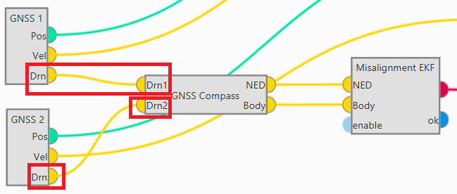
GNSS Compass Configuration - GNSS sensor and GNSS Compass blocks -
In addition, in order to properly use the of GNSS Compass values in navigation, the following values are recommended for the Misalignment EKF Block in cases where yaw misalignment occurs:
- Norm diff. threshold: Should be around 10-20%.
- Minimum norm: Should be around 50% of the absolute distance between the antennas.
- Norm filter: 0.1.
- Decimation: 10.
Therefore, in the Navigation program, the connections for GNSS should look like this:
-
Finally, go to Input/Output menu I/O Setup panel. A Base-to-Rover RTCM connection must be established.
In this example, the Base corresponds to GNSS2 and the Rover to GNSS1.
Therefore, connect the GPS 1 RTCM producer to the GPS 0 RTCM consumer.
Note
Note that the GNSS index starts from 0 in this panel so it will be GPS 1 RTCM = GNSS2 sensor and GPS0 RTCM = GNSS1 sensor.
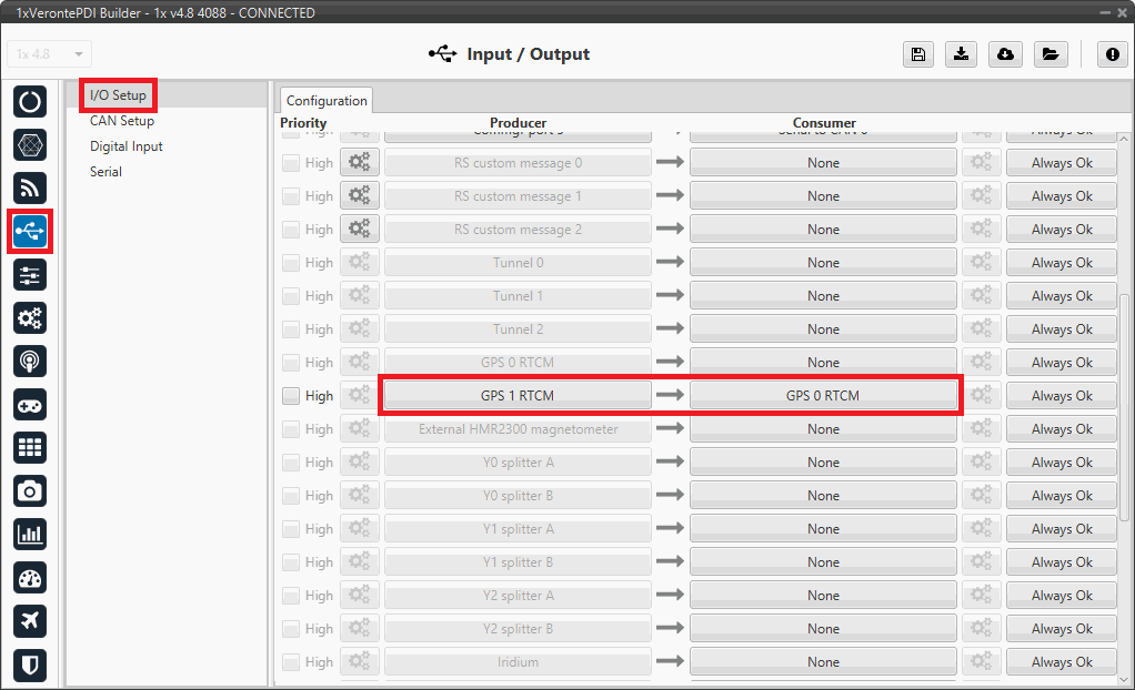
GNSS Compass configuration - I/O Setup configuration
RTK Configuration
The RTK configuration is performed through the GNSS sensor block with the help of the RTK Wizard.
Users must use this wizard to perfom the corresponding settings for the 1x air and ground units:
Danger
This wizard uses by default the Y0 splitter port. Consequently, if it has been configured for another use, the configuration will be now overwritten.
Therefore, to avoid system malfunction when using RTK, it is highly recommended to leave the Y0 splitter on the ground unit "free".
This is especially important if the ground unit is a PCS.
-
For the 1x air unit, click on "Air" in the RTK column and the corresponding RTK configuration will be automatically applied to the user's configuration.
-
For the ground unit, click on "Ground" in the RTK column and the corresponding RTK configuration will be automatically applied to the user's configuration.
In the Ublox preset parameter, the Static base option will be selected. However, if user wishes to consult the configuration made, just select the Custom option:
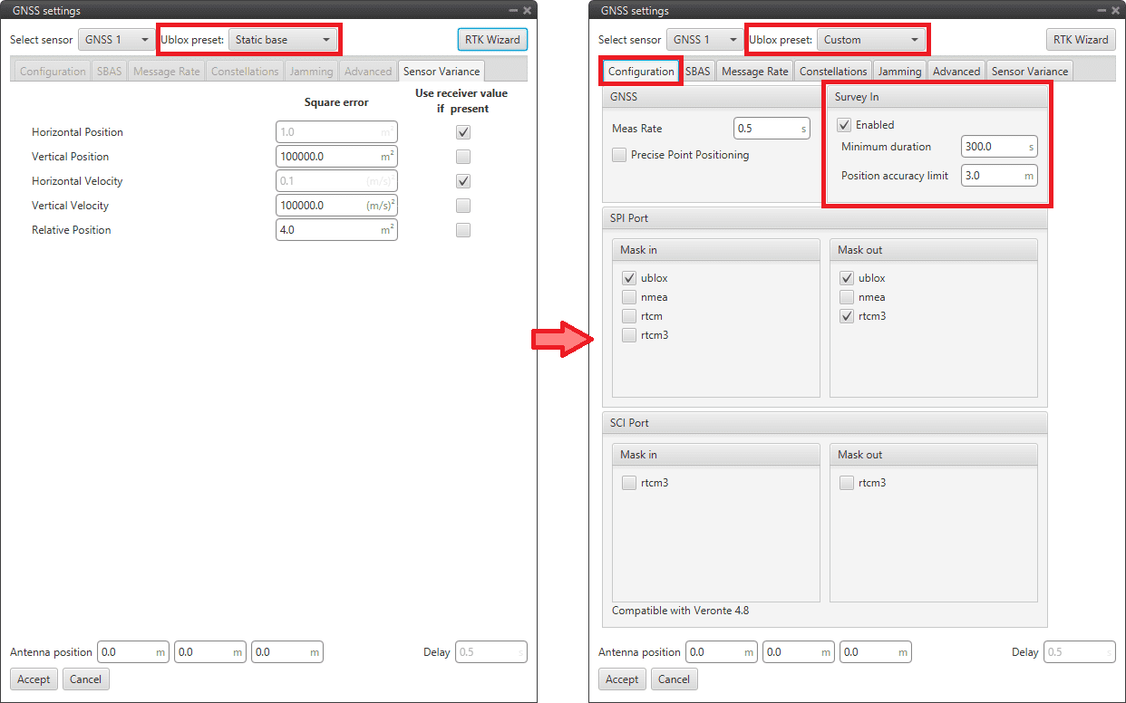
RTK Configuration - GNSS block ground configuration
Important
Please pay specific attention to the "survey configuration" options.
For a detailed explained of the GNSS sensor block, please refer to GNSS sensor - Sensors blocks of Block Programs section.
With the previous configurations, when GNSS accuracy < 3 m GNSS sensor will start the survey in during 300 seconds while taking measurements for RTK correction.
To verify correct survey in behavior, in Veronte Ops users can query the status of the following variables.
-
In the ground unit, if the survey in has started, 'GNSS1 Survey In Off' bit should be in "success" mode GNSS1 Survey In (if the label has the default setting, it will be green).
Therefore, when finished, the bit will switch to "fail" mode GNSS1 Survey In Off (if the label has the default setting, it will be colored red).
-
On the 1x air unit, once the survey in has finished, check that 'DGNSS1 Input Off' and 'DGNSS1 Navigation Off' bits are in "success" mode DGNSS1 Input On and DGNSS1 Navigation On respectively (if the labels have the default setting, they will be colored green).
At this time, the GNSS1 Accuracy value in the air unit, should be very low, probably between 0.01-0.05 m.
Serial communication
Here are described the steps to be followed in order to correctly receive and transmit Serial messages, both via CAN and serial interfaces.
Serial messages transmission
This section summarizes the configuration to be carried out to send Serial streams over a serial bus.
-
Go to Input/Output menu I/O Setup panel.
Connect a RS custom message producer (in this case RS custom message 0 has been chosen) to a Serial port, in this example RS232 is selected:
Note
Serial ports: Veronte LOS, RS232, RS485 and External UART
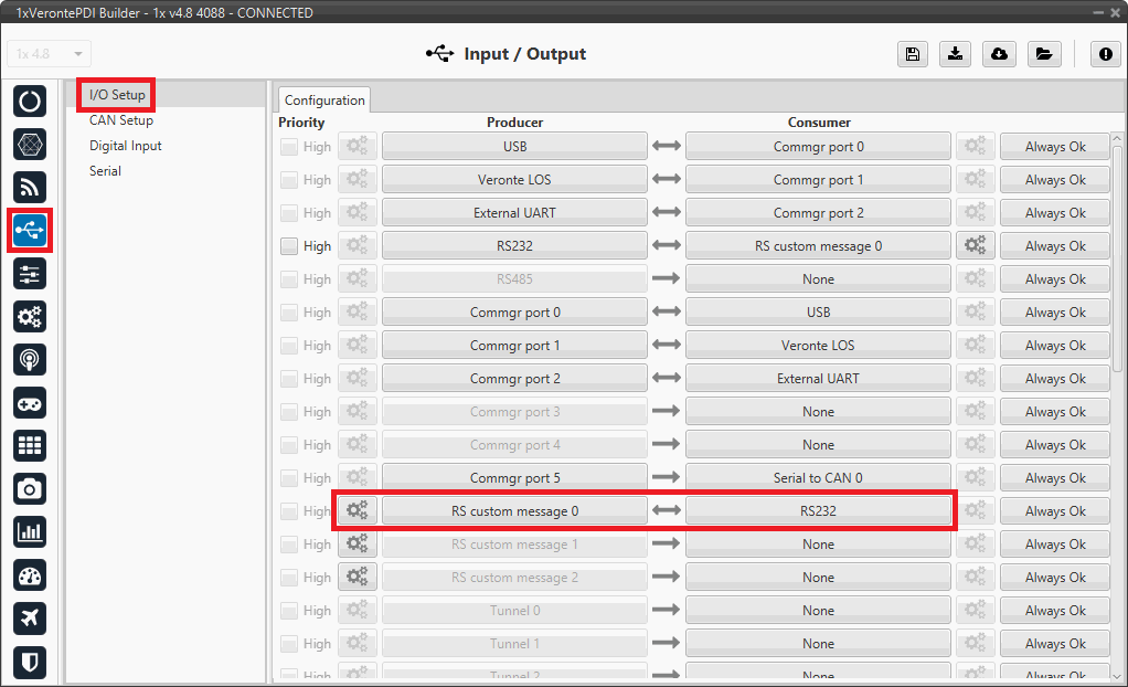
Serial messages transmission - I/O Setup configuration -
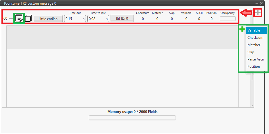
Click on the configuration button (
 icon) and a pop-up window will be displayed.
More information on the configuration of serial custom messages can be found in the Serial Custom Messages - Input/Output section of this manual.
For example:
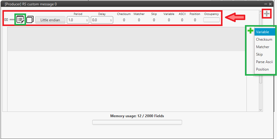
Serial messages transmission - RS custom message configuration -
Go to Input/Output menu Serial panel RS232 tab (as RS232 has been selected as consumer).
Configure the serial port parameters according to the user's specifications. For example:
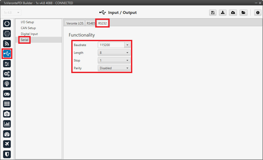
Serial messages transmission - Serial configuration Important
The serial parameters for the External UART port cannot be modified by the users and are fixed at:
- Baudrate: 115200
- Length: 8
- Stop: 1
- Parity: Disabled
Serial messages reception
This section summarizes the configuration to be carried out to receive Serial streams over a serial bus.

-
Go to Input/Output menu Serial panel Serial port tab (in this case RS232 port has been chosen).
Configure the serial port parameters according to the user's specifications. For example:
Serial messages reception - Serial configuration Important
The serial parameters for the External UART port cannot be modified by the users and are fixed at:
- Baudrate: 115200
- Length: 8
- Stop: 1
- Parity: Disabled
-
Go to Input/Output menu I/O Setup panel.
Connect the RS232 producer to a RS custom message consumer, in this example RS custom message 0 is selected:
Note
The serial port producer to configure must match the serial port configured in the previous step. In this example, RS232 is selected.
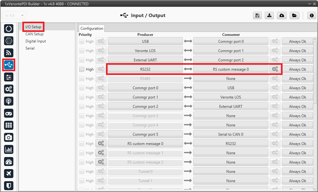
Serial messages reception - I/O Setup configuration -
Click on the configuration button (
icon) and a pop-up window will be displayed.Configure the message reading as desired. The different options and parameters to be configured are explained in the Serial Custom Messages - Input/Output section of this manual.
Serial messages reception - RS custom message configuration
Serial messages transmission via CAN bus
This section summarizes the configuration to be carried out to send Serial streams over a CAN bus.
Note
For sending Serial streams over a CAN bus, a Serial to CAN port is needed. For further details of this port, please consult the CAN to serial/Serial to CAN - I/O Setup section of the present manual.
-
Go to Input/Output menu I/O Setup panel.
Connect a RS custom message producer to a Serial to CAN consumer, in this case RS custom message 0 and Serial to CAN 0 have been selected:
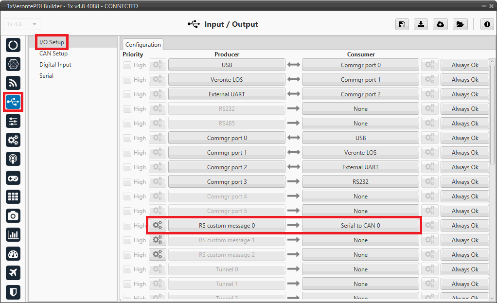
Serial messages transmission via CAN - I/O Setup configuration -
Click on the configuration button (
icon) and a pop-up window will be displayed.More information on the configuration of serial custom messages can be found in the Serial Custom Messages - Input/Output section of this manual.
For example:
Serial messages transmission via CAN - RS custom message configuration -
Go to Input/Output menu CAN Setup panel Configuration tab.
Connect the Serial to CAN 0 producer to an Output filter consumer, in this case Output filter 0 has been chosen.
Important
The Serial to CAN producer index must match the one previously selected as Serial to CAN consumer in the I/O Setup panel.
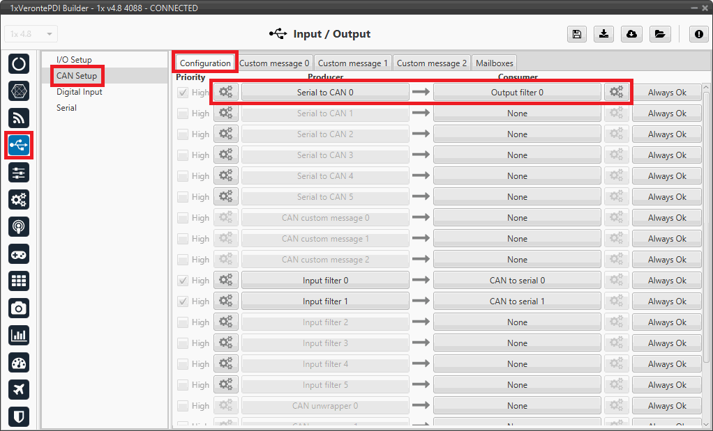
Serial messages transmission via CAN - CAN Setup configuration -
Configure the parameters of the Serial to CAN producer by clicking on the
icon.For more information on these parameters, refer to the CAN Setup - Input/Output section of this manual.
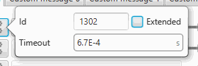
Serial messages transmission via CAN - Serial to CAN configuration -
Configure the Output filter consumer by clicking on the
icon.
Set it to the CAN port used, in this example CAN A port.For more information on this parameter, refer to the CAN Setup - Input/Output section of this manual.
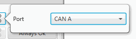
Serial messages transmission via CAN - Output filter configuration
-
Warning
Remember that it is necessary to have at least 1 free mailbox for transmission messages.
Serial messages reception via CAN bus
This section summarizes the configuration to be carried out to receive Serial streams over a CAN bus.
Note
For receiving Serial streams over a CAN bus, a CAN to serial port is needed. For further details of this port, please consult the CAN to serial/Serial to CAN - I/O Setup section of the present manual.

-
Go to Input/Output menu CAN Setup panel Mailboxes tab.
Configure at least one mailbox to receive the message with the appropiate ID.
For more information on mailboxes configuration, please refer to the Mailboxes - Input/Output section of the present manual.
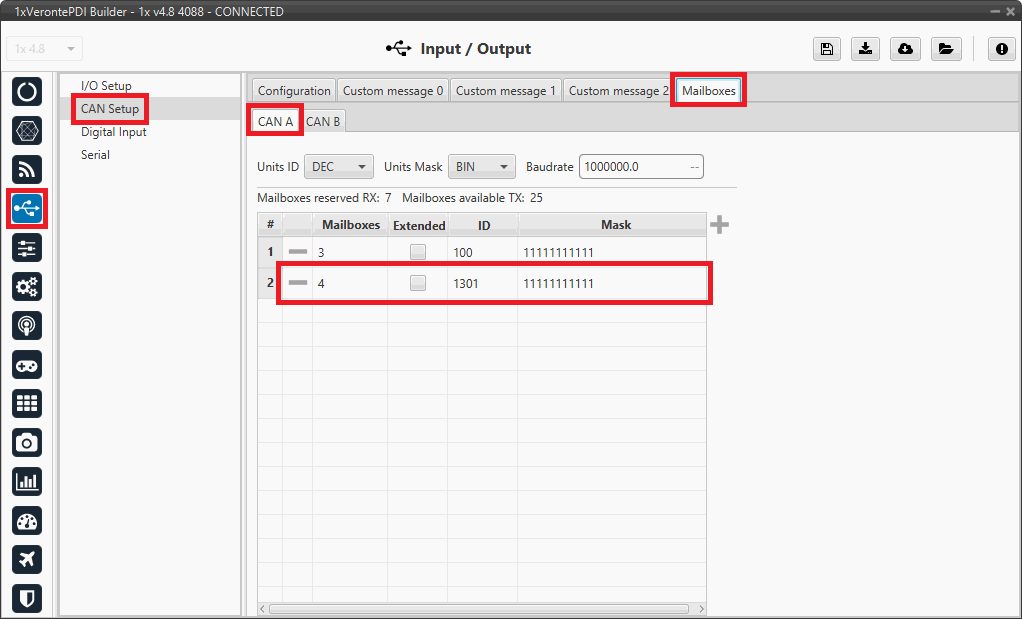
Serial messages reception via CAN - Mailboxes configuration -
Go to Input/Output menu CAN Setup panel Configuration tab.
Connect an Input filter producer to a CAN to serial consumer. In this example, Input filter 0 has been connected to CAN to serial 0.
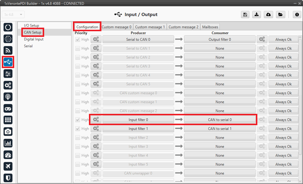
Serial messages reception via CAN - CAN Setup configuration -
Configure the parameters of the Input filter producer by clicking on the
icon.The configuration must be the same as for the mailbox to correctly receive the message.
For more information on these parameters, refer to the CAN Setup - Input/Output section of this manual.
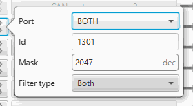
Serial messages reception via CAN - Input filter configuration
-
-
Go to Input/Output menu I/O Setup panel.
Connect the CAN to serial 0 producer to a RS custom message consumer, in this example RS custom message 0 has been chosen.
Important
The index of the CAN to serial producer must match the index of the CAN to serial consumer configured in the previous step.
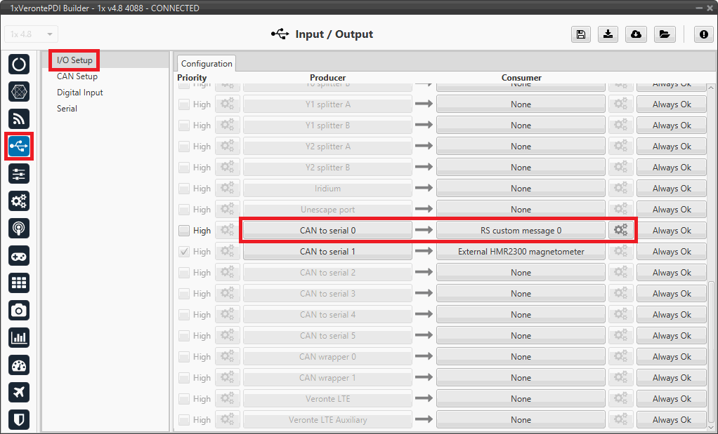
Serial messages reception via CAN - I/O Setup configuration -
Click on the configuration button (
icon) and a pop-up window will be displayed.Configure the message reading as desired. The different options and parameters to be configured are explained in the Serial Custom Messages - Input/Output section of this manual.
Serial messages reception via CAN - RS custom message configuration
External devices
The step-by-step instructions for the following external devices will be explained in detail in the following sections:
© 2025 Embention. All rights reserved.