Veronte products
Autopilot 4x
Veronte Autopilot 4x is a redundant system that includes 3 complete Veronte Autopilots 1x modules fully integrated with dissimilar arbiters.
Normally, the configuration development is done for one Autopilot 1x unit, however, to integrate it into a Veronte Autopilot 4x, several modifications must be made to the 3 units for a correct operation of the 4x system.

This section presents:
- Autopilots 1x configuration Configuration required on an Autopilot 1x as far as being part of an Autopilot 4x is concerned:
Caution
Arbitration configuration is conducted in Arbiters using the 4x PDI Builder software. For more information on this, please refer to the Arbitration configuration - Integration examples section of the 4x PDI Builder user manual.
- Configuration for external radio communication through RS232 Configuration to establish communication between Autopilot 4x and an external radio connected to its multiplexed RS232, as well as CAN communication between the Autopilots 1x.
- Arbiters communication Configuration necessary to establish the connection between the PC and Arbiters using one of the Autopilots 1x as a "tunnel".
Important
These examples are valid for Veronte Autopilot 4x hwv 1.8 and higher.
This is because the 4X Selected bit variable used throughout this explanation has been introduced from Autopilot 4x hwv 1.8.
However, if users have a 4x with a lower hwv, they can follow all the steps by simply replacing this bit with the corresponding bit coming from the arbiter status message. For more information on the status message, see Status Message - CAN Bus protocol section of the 4x Software Manual
Autopilots 1x configuration
This example describes the steps necessary to adapt a complete and functional configuration of an Autopilot 1x to that of an Autopilot 1x within an Autopilot 4x.
The following schema broadly summarizes the configuration that will be explained:

Important
All the Ids represented in the schema are the default ones and those that will be used throughout this example, but users can change them as they wish.
Nonetheless, the Ids designated for arbitration in this configuration must match those entered in the arbitration configuration of the 4x PDI Builder software.
| AP 0 | AP 1 | AP 2 | |
|---|---|---|---|
| Ids for arbitration | 8 | 9 | 10 |
| CAN Ids for control | 48 | 49 | 50 |
In this example, AP 0 is configured, so the Ids associated with it are 8 for arbitration and 48 for control.
Definition of the 4x group
Firstly it is necessary to indicate that this Veronte Autopilot 1x is part of a Veronte Autopilot 4x.
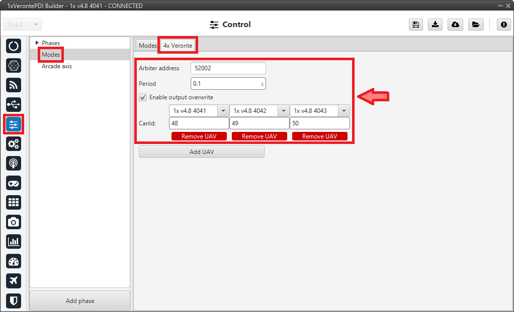
For this purpose, go to Control menu Modes panel 4x Veronte tab:
-
Enter the Arbiter address:
Arbiter A address = 50000 + Serial number of 4x
Arbiter B address = 54000 + Serial number of 4x
Note
Arbiter A is configured in this example.
-
Activate the Enable output overwrite so that the autopilots that are not in command (the ones not selected) give the same control output as the selected autopilot.
This way, when the selected autopilot changes (due to arbitration), the transition in control commands is smooth.
-
Add the 3 Autopilots 1x that are part of the Autopilot 4x by clicking on Add UAV and specifying their addresses (address = Serial number).
-
For each autopilot set the CAN Id to be used for the control messages.
Note
Control Ids described above have been entered here.
Control and communication between autopilots within the 4x group
Then, in order for the Autopilots 1x to send control commands to each other, it is necessary to configure the CAN communication. To do this:
Note
Remember that this is an example of the configuration for AP 0.
-
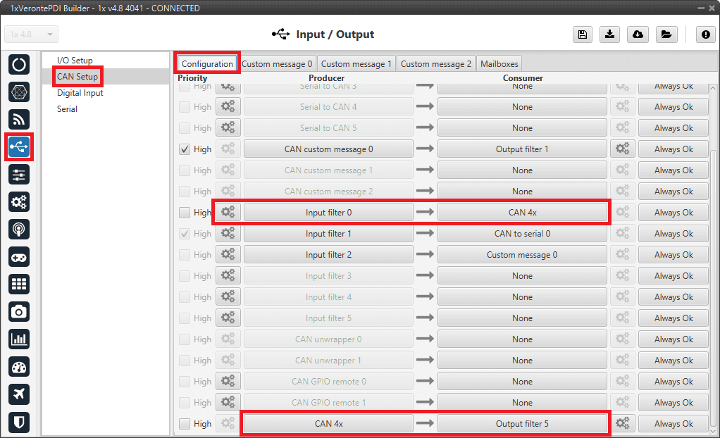
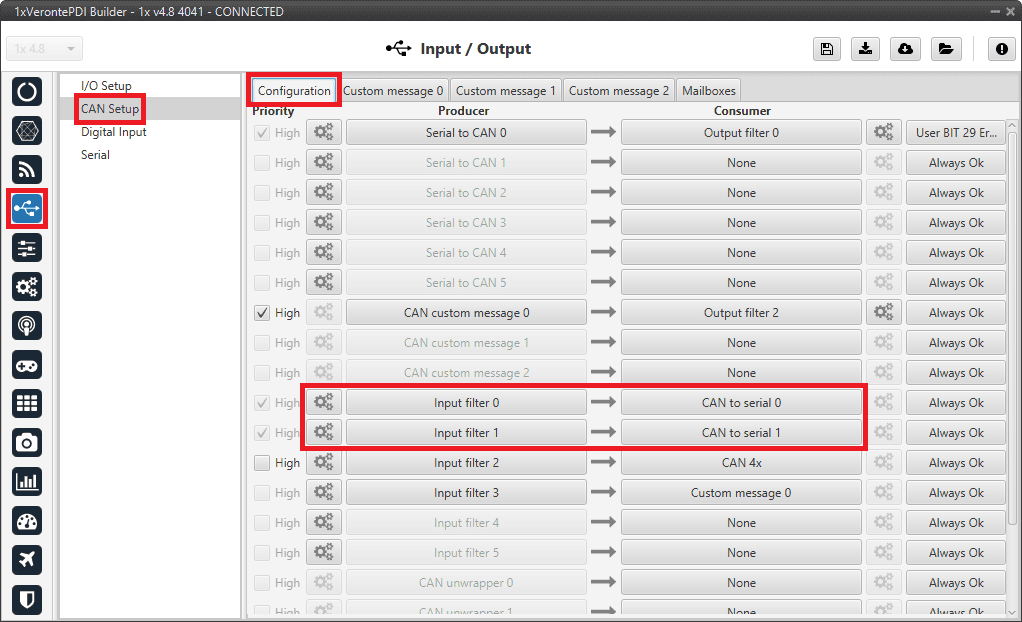
Go to Input/Output menu CAN Setup panel Configuration tab.
- For sending commands from this autopilot, connect the CAN 4x producer to an Output filter consumer configured to CAN A, in this case Output filter 5 has been selected.
-
For receiving commands from the other autopilots, connect an Input filter producer to the CAN 4x consumer, in this case Input filter 0 has been selected.
Therefore, in order to read control command messages from all autopilots, it is necessary to correctly configure the Id and mask in this Input filter.
That is, by setting the Id to 48 and the mask to 2044 (decimal format), command messages from 48 to 50 will be read.
Note
The following table shows the Ids and mask in binary and decimal format used in this example.
Decimal format Binary format AP 0 control Id 48 000 0011 0000 AP 1 control Id 49 000 0011 0001 AP 2 control Id 50 000 0011 0010 Mask 2044 111 1111 1100
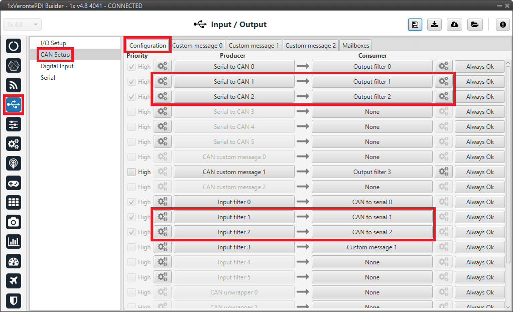
Autopilots 1x configuration - CAN Setup configuration 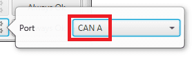
Autopilots 1x configuration - Output filter configuration 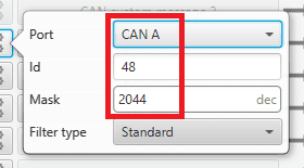
Autopilots 1x configuration - Input filter configuration -
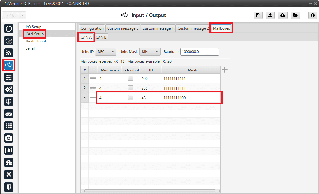
Go to Input/Output menu CAN Setup panel Mailboxes tab.
Configure at least 4 mailboxes in CAN A bus with the same configuration as the Input filter to correctly receive the control command messages:
ID: 48 DEC
Mask: 111 1111 1100 BIN
Autopilots 1x configuration - Mailboxes configuration -
Go to Block Programs menu.
-
In all programs using "Control Output uX" variables, it is necessary to add the AP Selection block between these variables and the corresponding control block, usually the PID Static block. For example:
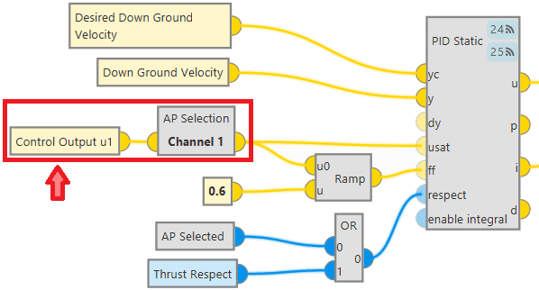
Example of AP Selection block connection This connection is performed to always use the control output of the selected AP as input to the corresponding control block, usually the PID Static block.
Therefore, the input of the AP Selection block is the control output of the AP in the configuration and the output is the control output of the selected AP.
In the configuration of this block, users only have to select the channel through which the information related to this control output is being shared. For example, if Control Output u1 is connected to this block, channel 1 must be selected. For more information on this block, see the AP Selection - Mode/AP Selection blocks in the Block Programs section of this manual.
Warning
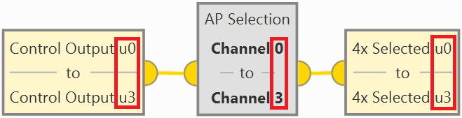
This block only allows to select the same channel once in all programs, i.e. this block can only be used once for each control output.
Consequently, if a control output is used more than once in the programs, users must create an auxiliary program in which they connect each Control Output uX to the AP Selection block and save this "transformation" in user variables. Then, they will be able to use these user variables throughout the programs as many times as they need.
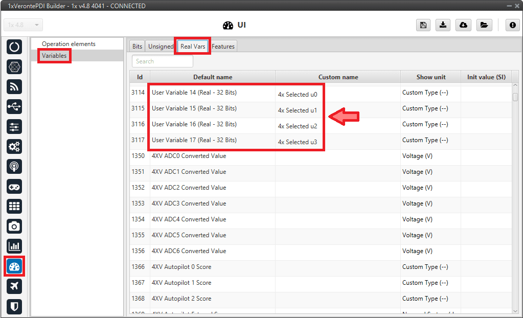
Below is an example in which all the control outputs used in the configuration have been associated to renamed user variables:
Example of AP Selection block connection to several Control Outputs These users variables have been previously renamed in the UI menu Variables panel Real Vars tab:
User variables renamed
-
Furthermore, build the following library block, "AP Selected", to be used as the respect input of the corresponding control block, usually the PID Static block.
- Go to the Library tab.
- Add a new block by clicking on
 and rename it as desired, in this example AP Selected.
 - Insert in this custom block the "NOT" and "Read Bit" blocks.
- Right click on the custom block and add an output to it.
- Connect the "Read Bit" block as input of the "NOT" logic block and as iy¡ts output, the output that has been added to the custom block.
- Finally, select the 4X Selected variable for the "Read Bit".
For more information on library blocks, see Library blocks - Block Programs section of this manual.
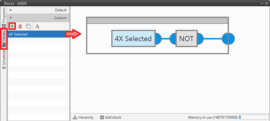
Autopilots 1x configuration - Library block
The overall result of these blocks related to 4x should look like this:
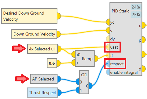
Autopilots 1x configuration - Blocks With all this block configuration, the expected behavior is to avoid jumps in the control commands when the selected autopilots change (due to arbitration). This is achieved by always having as usat input of the PID Static block the control output of the selected AP, since the integral term of the 3 Autopilots 1x of group 4x always remains the same.
And the logic that follows is this:

Autopilots 1x configuration - Blocks logic -
Communication between Autopilots 1x and Arbiter
Finally, the CAN communication must be correctly configured to be able to send the Ready and Arbitration messages from the autopilots to the arbiter and to read the Status and Score messages from the arbiter:
Note
The structure/configuration of these messages must be done following the protocol defined in the CAN Bus protocol section of the 4x Software Manual.
Remember that this is an example of the configuration for AP 0.
-
Go to Input/Output menu CAN Setup panel Configuration tab.
- For sending messages to the arbiter, connect a CAN custom message producer to an Output filter consumer, in this case CAN custom message 0 and Output filter 1 have been selected.
- For receiving messages from the arbiter, connect an Input filter producer to a Custom message consumer, in this case Input filter 2 and Custom message 0 have been selected.
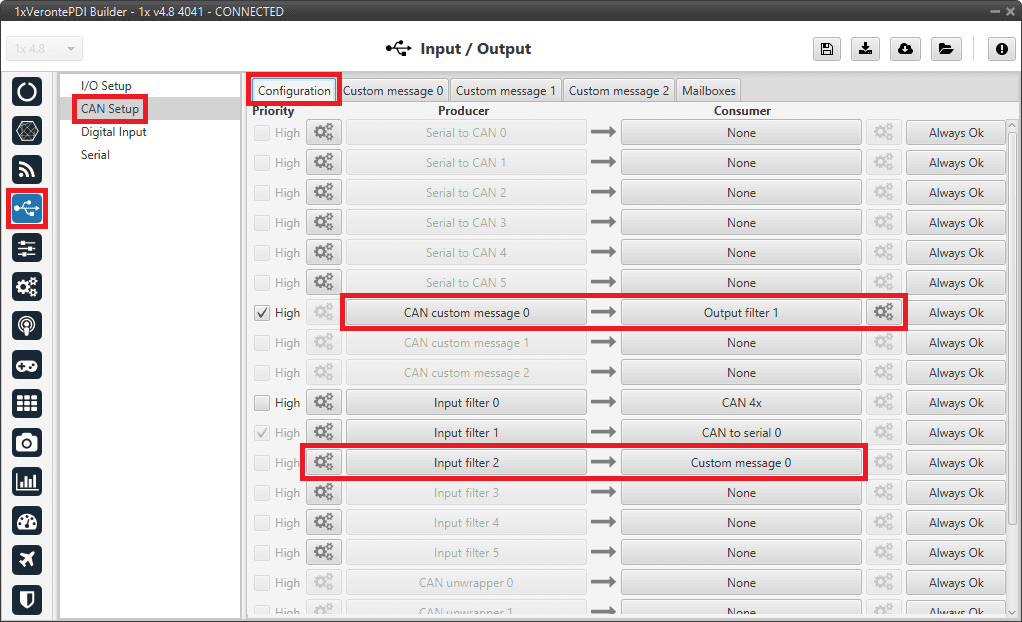
Autopilots 1x configuration - CAN Setup configuration -
The Output filter is configured to both CAN ports:
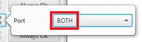
Autopilots 1x configuration - Output filter configuration -
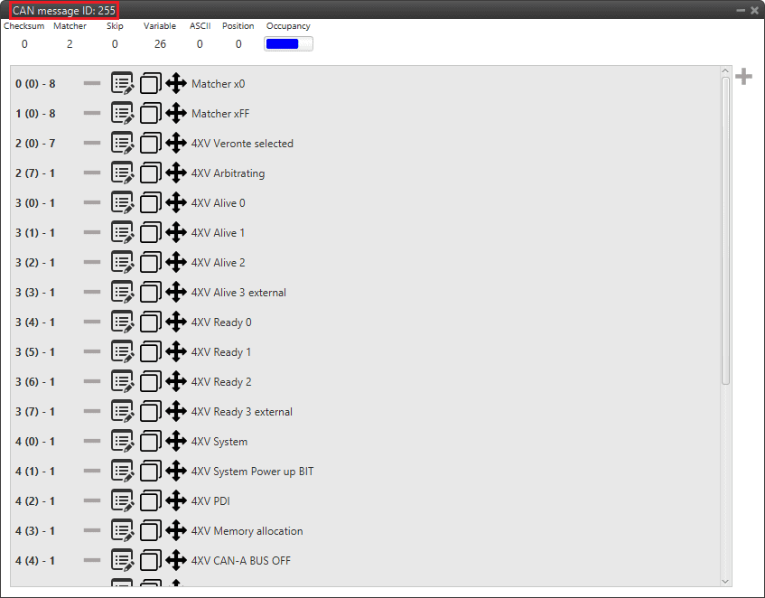
The Id set in this Input filter must match the status Id set in the arbiter configuration. In this example Id 255 has been chosen:
Autopilots 1x configuration - Input filter configuration
-
Go to Input/Output menu CAN Setup panel Custom Message 0 tab (since CAN custom Message 0 has been connected to the output filter) TX to configure the messages to be sent to the arbiter.
-
In this example, 5 messages with CAN ID 8 (arbitration Id of the AP 0), Little endian and Period 0.05 s have been added. More information on CAN messages configuration can be found in the TX/TX Ini Messages (Custom Messages) - Input/Output section of this manual.
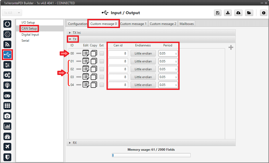
Autopilots 1x configuration - CAN custom message 0 (TX) configuration -
Then, to create each message, click on its corresponding
 button:
-
ID 00 Ready message. It must be built following the Ready Message - CAN Bus protocol section of the 4x Software Manual.
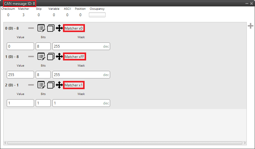
Autopilots 1x configuration - Ready message -
ID 01-04 Arbitration variables messages. They must be built following the Arbitration Message - CAN Bus protocol section of the 4x Software Manual.
In this example, Roll, Pitch, Position not fixed and a Custom Arbitration Variable have been configured as arbitration messages:
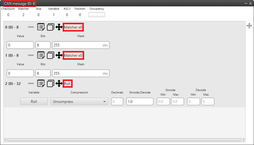
Autopilots 1x configuration - Roll message 
Autopilots 1x configuration - Pitch message Note
The "Position not fixed" variable, which is of type bit, has had to be "converted" as follows to a real variable (single-precision float), since that is the type of variable expected by the arbiter.
Autopilots 1x configuration - Position not fixed message 
Autopilots 1x configuration - Custom Arbitration Variable message
For more information on configuring CAN custom messages, refer to the Custom Messages types - Input/Output section of this manual.
-
-
-
Go to Input/Output menu CAN Setup panel Custom Message 0 tab (since Custom Message 0 has been connected to the input filter) TX to configure the messages to be read from the arbiter.
-
Add 4 messages and configure them as follows:
ID Can id Endianness Time out Bit ID 00 255 Little endian 1.0 s 0 01 255 Little endian 4.0 s 1 02 255 Little endian 4.0 s 2 03 255 Little endian 4.0 s 3 More information on CAN messages configuration can be found in the RX Messages (Custom Messages) - Input/Output section of this manual.
Autopilots 1x configuration - Custom messages 0 (RX) configuration -
Then, to create each message, click on its corresponding
button:-
ID 00 Status message. It must be built following the Status Message - CAN Bus protocol section of the 4x Software Manual.
Autopilots 1x configuration - Status message -
ID 01-03 Scores messages. They must be built following the Score Message - CAN Bus protocol section of the 4x Software Manual.
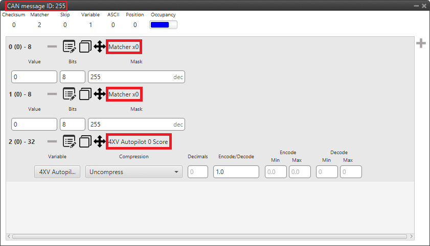
Autopilots 1x configuration - AP 0 Score message 
Autopilots 1x configuration - AP 1 Score message 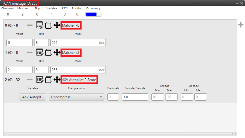
Autopilots 1x configuration - AP 2 Score message
For more information on configuring CAN custom messages, refer to the Custom Messages types - Input/Output section of this manual.
-
-
-
Go to Input/Output menu CAN Setup panel Mailboxes tab.
Configure at least 4 mailboxes in CAN A bus with the same configuration as the Input filter to correctly receive the messages from the arbiter:
ID: 255 DEC
Mask: 111 1111 1111 BIN
Warning
Remember that it is necessary to have at least 1 free mailbox for TX messages.
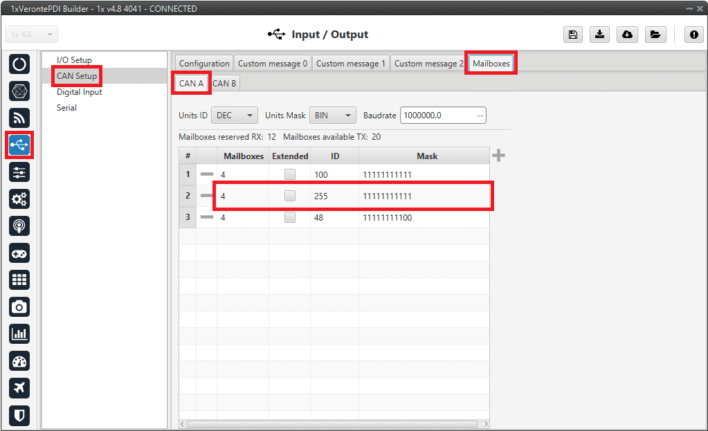
Autopilots 1x configuration - Mailboxes configuration
Important
After making this configuration for AP 0, users will have to upload the same configuration on AP 1 and AP 2 and change the IDs of the CAN messages configured for sending messages (TX) to the arbiter.
For AP 1 it will be necessary to change the Id 8 to 9, and for AP 2, to change it to 10.
It is also advisable to slightly modify the name of the configuration to be able to distinguish them quickly. This is done from the Unit name panel.
Warning
The Arbiter address parameter must be set again when uploading the configuration to another AP. This is because this address is unique for each Autopilot 4x and it is not exported when downloading the configuration nor applied when uploading a PDI.
Configuration for external radio communication through RS232
The following is the configuration necessary to establish communication with an external radio connected to one of the multiplexed ports of Veronte Autopilot 4x, in this case RS232.
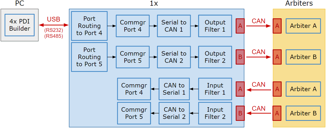
The purpose of this implementation is that the Autopilot 1x selected by the arbiter receives the communications from the other two autopilots via CAN and redirects them to the RS232 port to send them to the radio. As far as reception is concerned, this is not necessary since all 3 Autopilots 1x can receive communications over the RS232 port.
In addition, to avoid overloading the CAN bus with telemetry, the telemetry address has been changed to a dynamic address of Veronte applications and depending on whether the current autopilot is the selected AP or not, the routing of communications acts in one way or another:
- If it is the autopilot selected the telemetry is sent by the RS232.
- If it is not the autopilot selected the telemetry is redirected to a port that is not in use to avoid being sent by CAN.
The following schematic broadly summarizes the configuration that will be explained:

Important
The following are the IDs for CAN communications normally assigned to each AP, however users may use any IDs they wish:
| AP 0 | AP 1 | AP 2 |
|---|---|---|
| 100 | 101 | 102 |
In this example, AP 0 is configured, so Id 100 is associated with it.
The explanation of everything shown in the diagram above has been divided according to the different parts to configure:
- Telemetry configuration
- I/O ports configuration
- CAN communication configuration
- Routing configuration
Telemetry configuration
First, configure the custom telemetry to be sent via radio by adding a Data vector with the desired variables to a dynamic address of Veronte applications. To do this:
-
Go to Telemetry menu Telemetry panel.
- Click on
 to add a new data vector, which will be added by default with address 2 (App 2 Data to VApp).
 -
Then configure it as follows:
- Frequency: 15 Hz are recommended.
-
Address: Enter a dynamic address of Veronte applications, in this example 255 is used. For more information on the range of dynamic addresses and other available addresses, see List of Addresses - Lists of interest section of the 1x Software Manual.
Note
Users only need to enter the address, then the software will automatically recognize that it is a dynamic address of Veronte applications and replace it with "App dynamic address entered", in this case "App dynamic 255".
-
Add as much custom telemetry as needed.
For more information on configuring data vectors, see the Data vectors - Telemetry section of the present manual.
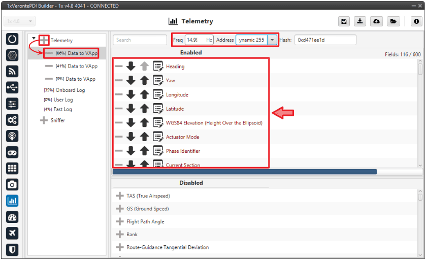
External radio communication through RS232 - Telemetry configuration - Click on
I/O ports configuration
Then, it is necessary to perform the ports connections for the sending and reception of CAN communications between Autopilots 1x.
In addition, it is recommended to use a user bit, which is the negation of the "4X Selected" bit (usually renamed to "4x not selected"), to disable the sending of these communications in the case where the current AP is the one selected by the arbiter. This is done to reduce the CAN bus traffic load.
For this purpose:
-
Go to UI menu Variables panel Bits tab.
Rename a user bit that is not being used for another purpose in the configuration to be the "4x not selected" bit.
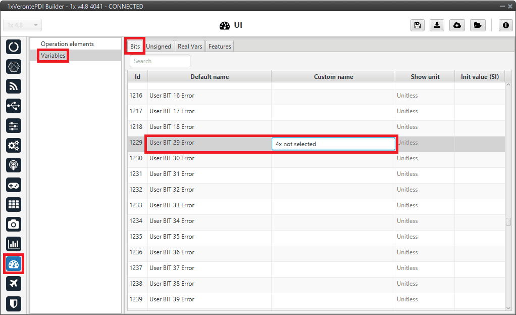
External radio communication through RS232 - User bit renamed -
Go to Block Programs menu.
Create a program to store the negation value of the "4X Selected" bit in the previously renamed user bit. To do this:
3.1. Add a new program by clicking on
and rename it as desired, in this example AP Communication.3.2. Configure it as a continuously running program (it should appear as
 ).
).3.3. Add the blocks "NOT", "Read Bit" and "Write Bit" to the created program.
3.4. Connect to the logic block "NOT" the "Read Bit" block as input and the "Write Bit" as output.
3.5. Select the variable 4X Selected for the "Read Bit".
3.6. Select for the "Write Bit" the user bit renamed as 4x not selected.
For more information on blocks, read Block Programs section of the present manual.
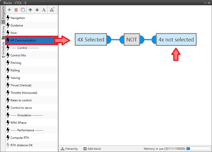
External radio communication through RS232 - User bit configuration -
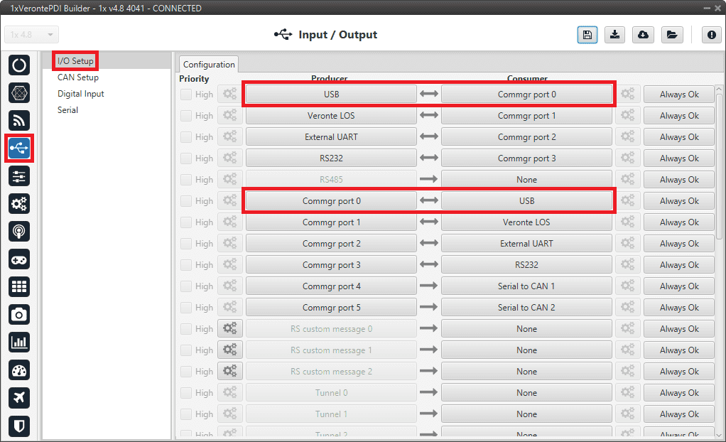
Go to Input/Output menu I/O Setup panel.
Several connections have to be made here for the different communications:
-
For the communicaction with the radio, a connection through RS232 port should be carry out:
Bidirectionally connect the RS232 producer to a Commgr port consumer, in this case Commgr port 3 is selected.
Then, the equivalent Commgr port producer (in this case Commgr port 3 producer) should automatically connect to the RS232 consumer.
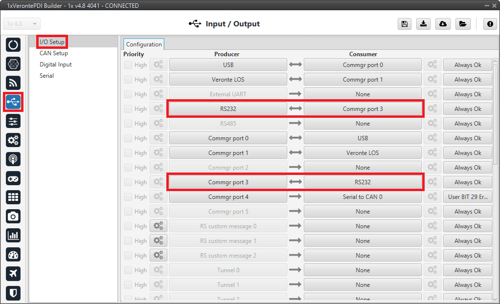
External radio communication through RS232 - I/O Setup configuration: Radio -
For the transmission of CAN communications from the current Autopilot 1x to the other Autopilots 1x, the following operation must be performed:
Connect a Commgr port producer to a Serial to CAN consumer, in this case Commgr port 4 and Serial to CAN 0 have been selected.
In addition, to disable the transmission in case this is the selected AP, the user bit previously configured in Block programs should be assigned to the connection (in this case, User BIT 29).
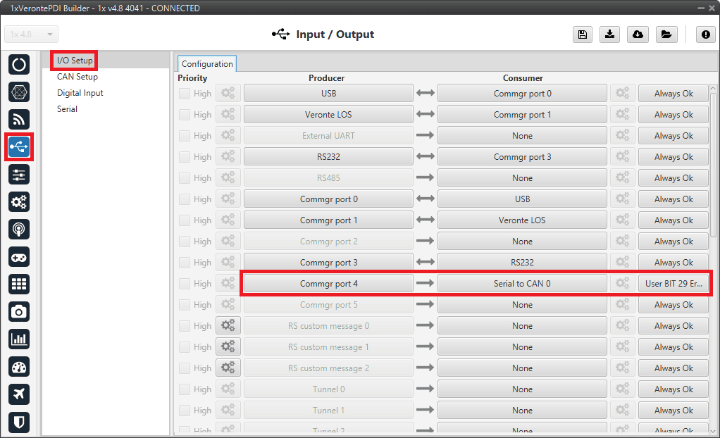
External radio communication through RS232 - I/O Setup configuration: Transmission -
For reception of CAN communications from the other Autopilots 1x on the current AP:
Connect two CAN to serial producers to two Commgr port consumers. In this case, CAN to serial 0 and CAN to serial 1 have been connected to Commgr port 4 and Commgr port 5 respectively.
External radio communication through RS232 - I/O Setup configuration: Reception
-
CAN communication configuration
Next, configure the sending of the CAN communication from the current AP to the other two Autopilots 1x as well as the reception of their communication.
In addition, it is also recommended to use the user bit "4x not selected" to disable sending CAN communications when the current AP is also the selected AP.
To do this:
-
Go to Input/Output menu CAN Setup panel Configuration tab.
The following settings must be made here for the different communications:
-
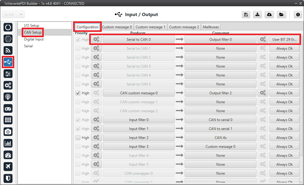
For the transmission of CAN communications from the current Autopilot 1x to the other Autopilots 1x:
Connect a Serial to CAN producer to an Output filter consumer, in this case Serial to CAN 0 and Output filter 0 have been selected.
Note
The Serial to CAN producer index must match the one previously selected as Serial to CAN consumer in the I/O Setup panel.
In addition, to disable the transmission in case this is the selected AP, the user bit previously configured in Block programs should be assigned to the connection (in this case, User BIT 29).
External radio communication through RS232 - CAN Setup configuration: Transmission -
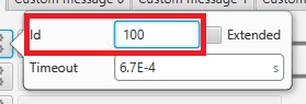
Serial to CAN producer should be set to Id 100 as this is the Id that has been assigned to the current AP.
External radio communication through RS232 - Serial to CAN configuration -
Output filter is configured to CAN A port.
External radio communication through RS232 - Output filter configuration
-
-
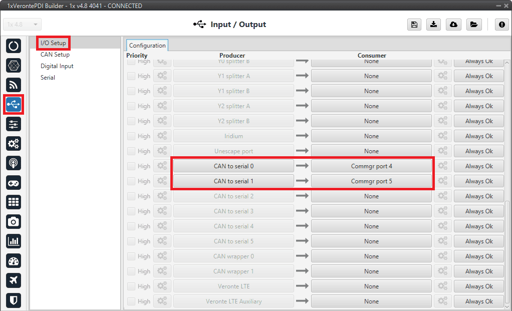
For reception of CAN communications from the other Autopilots 1x on the current AP:
Connect two Input filter producers to two CAN to serial consumers. In this case, Input filter 0 and Input filter 1 have been connected to CAN to serial 0 and CAN to serial 1 respectively.
Note
The CAN to serial consumers indices must match those previously selected as CAN to serial producers in the I/O Setup panel.
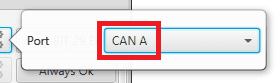
External radio communication through RS232 - CAN Setup configuration: Reception Input filter producers should be configure with the following parameters in order to correctly receive communications from the other two Autopilots 1x:
- Port: CAN A
- Id: 101 / 102 CAN Ids assigned to AP 1 and AP 2 respectively
- Mask: 2047
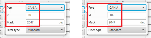
External radio communication through RS232 - Input filter 0/1 configuration
-
-
Go to Input/Output menu CAN Setup panel Mailboxes tab.
Configure at least 4 mailboxes on CAN A bus for receiving messages from each of the other two autopilots. They must have the same configuration as the Input filters to receive them correctly:
ID: 101 / 102 DEC
Mask: 111 1111 1111 BIN
Warning
Remember that it is necessary to have at least 1 free mailbox for TX messages.
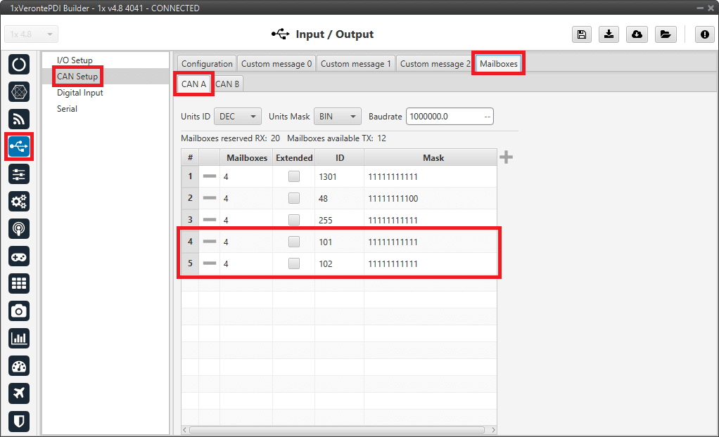
External radio communication through RS232 - Mailboxes configuration
Routing configuration
Finally, the following steps represent the necessary configuration to be performed by users for routing communications.
-
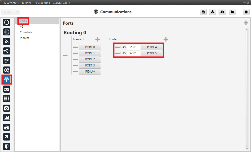
Go to Communications menu Ports panel.
2 routing configurations must be done:
-
Routing 0: This will be used when the current AP is also the selected AP. It is configured to output through PORT 3 (which is connected to RS232 on the I/O Setup panel) the following:
- All messages with address 2 Status messages from both the selected AP and the other 2 Autopilots 1x.
- All messages with address 255 Custom telemetry that has been configured to this dynamic address of Veronte applications.
-
Routing 1: This will be used when the current AP is not the selected AP. It is configured to force telemetry with address 255 (custom telemetry) to be redirected to a port that is not in use, in this case PORT 5.
For more information on the configuration of this panel, see the Ports - Communications section of the present manual.
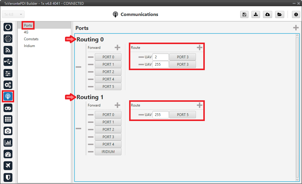
External radio communication through RS232 - Routing configuration -
-
Go to Automations menu.
To switch between both routing configurations it is necessary to create 2 automations that will be triggered depending on whether the current autopilot is the selected AP or not (with the value of the 4X Selected variable).
First, create an automation to select the routing configuration when the current AP is also the selected AP Routing 0 configuration. To do this:
- Click on the New automation button and rename it as desired, in this example 4x routing table 0.
-
Go to Events side and configure an Alarm event as follows:
- Enter a custom name for this event, AP Selected has been entered.
- Select All ok in the Type option, as it is desired that the action is triggered when the bit is in the "true" state.
- Click on to add the variable that has to activate the alarm 4X Selected bit.
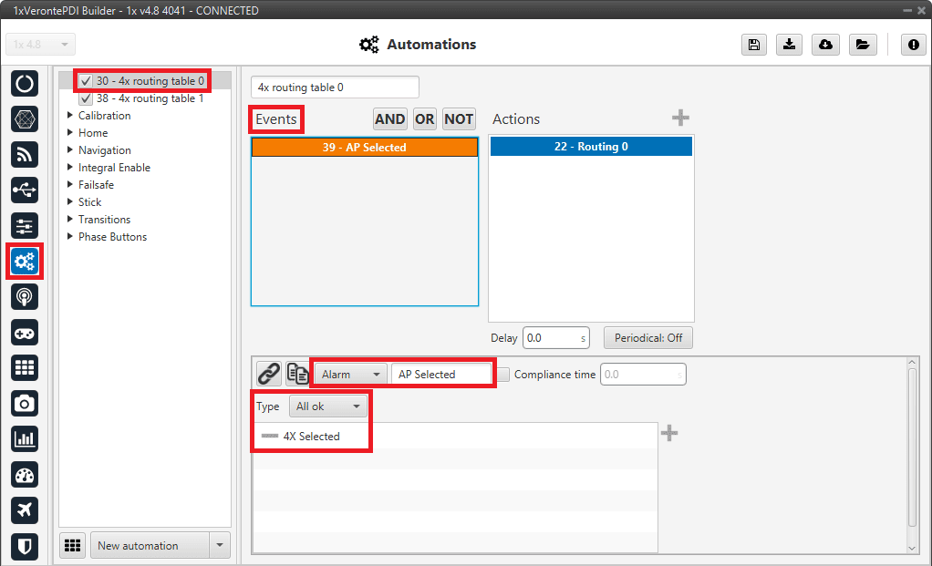
External radio communication through RS232 - Routing 0 event -
Go to Actions side, add a new Ports action and configure it as follows:
- Enter a custom name for this action, Routing 0 has been chosen.
- Select the Routing 0 option as this is the automation to select the previously defined Routing 0 configuration.
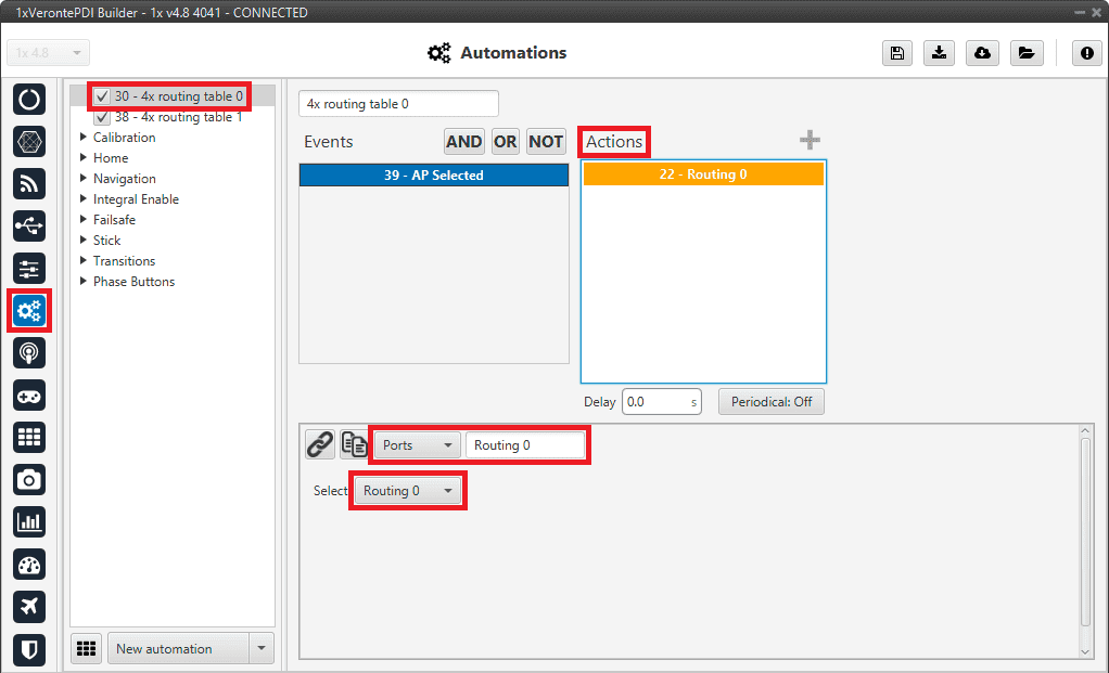
External radio communication through RS232 - Routing 0 action For more information on the configuration of these automations, see Automations section of this manual.
Repeat the same steps (with slightly differences) to create the automation in case this is not the selected AP and the Routing 1 configuration must be used:
- Click on the New automation button and rename it as desired, in this example 4x routing table 1.
-
Go to Events side, select the previously created event "AP Selected" and add to it the NOT boolean operation.
Therefore, the action will be triggered when the 4X Selected bit is in "false" state.
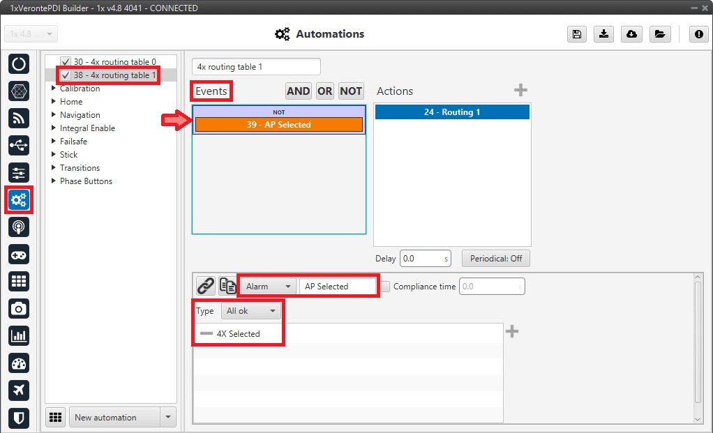
External radio communication through RS232 - Routing 1 event -
Go to Actions side, add a new Ports action and configure it as follows:
- Enter a custom name for this action, Routing 1 has been chosen.
- Select the Routing 1 option as this is the automation to select the previously defined Routing 1 configuration.
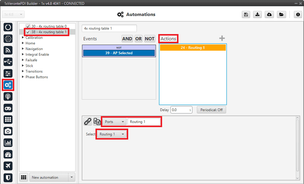
External radio communication through RS232 - Routing 1 action
Important
After making this configuration for AP 0, users will have to upload the same configuration on AP 1 and AP 2 and change the CAN communications IDs configured in CAN Setup panel:
| IDs | Serial to CAN 0 producer | Input filter 0 producer | Input filter 1 producer | Mailboxes for AP 0 messages | Mailboxes for AP 2/1 messages |
|---|---|---|---|---|---|
| AP 1 | 101 | 100 | 102 | 100 | 102 |
| AP 2 | 102 | 100 | 101 | 100 | 101 |
It is also advisable to slightly modify the name of the configuration to be able to distinguish them quickly. This is done from the Unit name panel.
Arbiters communication
As it is sometimes not possible to connect the Arbiters, which are inside the Veronte Autopilot 4x, directly to the PC to configure them (access 4x PDI Builder), Veronte Autopilot 1x is connected to the PC and a connection is made between Arbiters and Autopilot 1x via CAN.
Important
Arbiter B can only be configured in this way.
To be able to communicate with Arbiters via CAN, the following connection is required:
Follow the steps below to make this configuration:
-
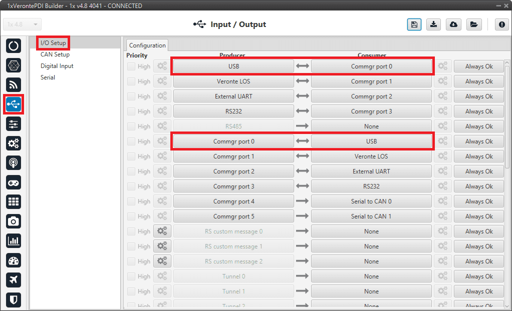
Go to Input/Output menu I/O Setup panel.
Check the connection between the computer and the Autopilot 1x (usually via USB, but RS232 and RS485 are also possible).
Arbiters communication - I/O Setup configuration: PC connection -
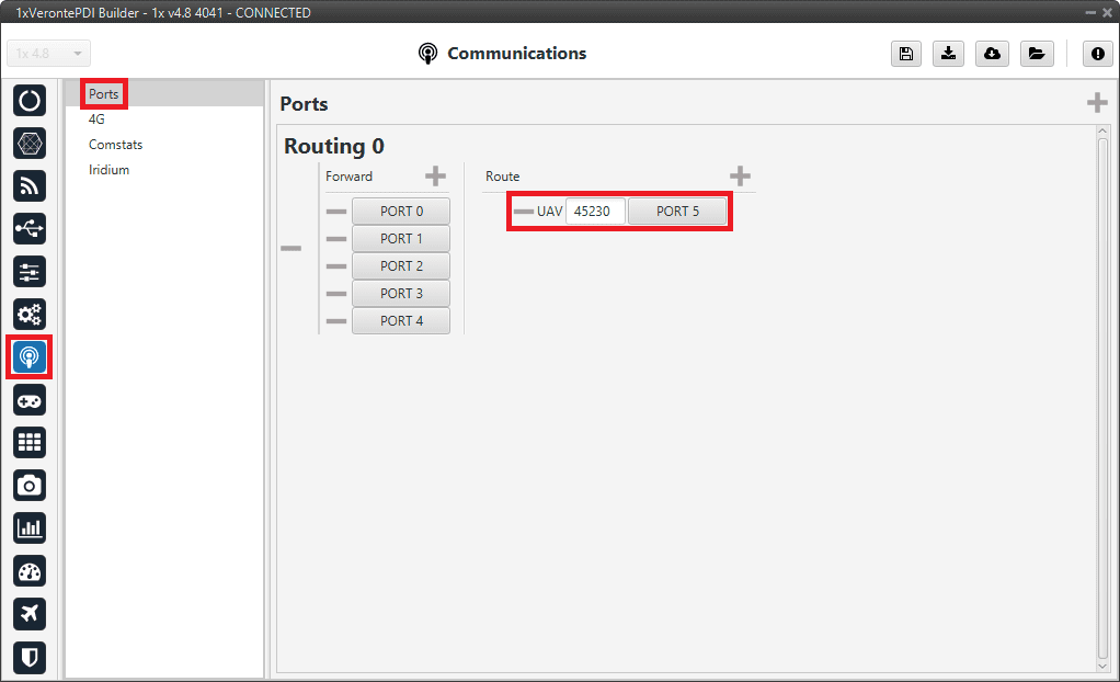
Go to Communications menu Ports panel.
Remove Port 4 and 5 from the Forward group and add Port 4 and 5 to the Route group, with target Arbiters' Address:
- Address of Arbiter A: 50 000 + Serial number of 4x
- Address of Arbiter B: 54 000 + Serial number of 4x
Arbiters communication - Routing configuration Note
This is just an example, users can choose Ports other than 4 and 5.
-
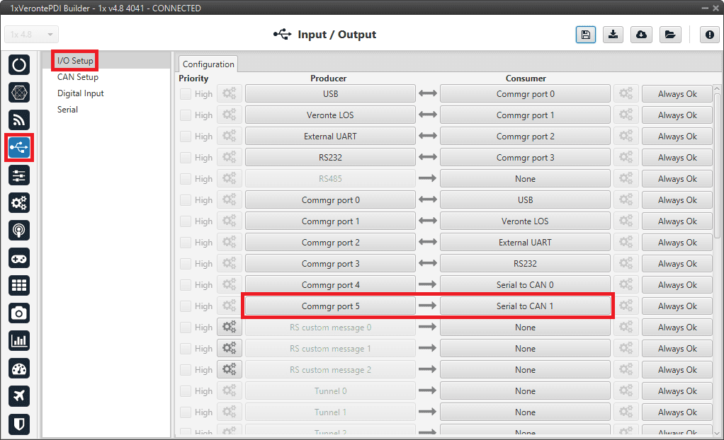
Go to Input/Output menu I/O Setup panel.
Connect Commgr port 4 to Serial to CAN 1 consumer and Commgr port 5 to Serial to CAN 2 consumer:
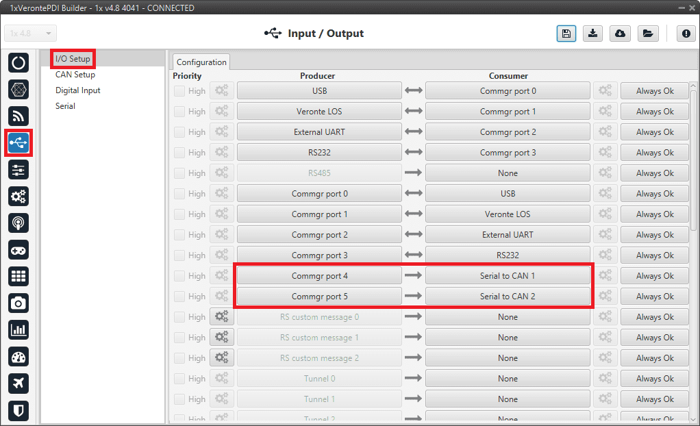
Arbiters communication - I/O Setup configuration: Serial to CAN Then, connect CAN to serial 1 to Commgr port 4 and CAN to serial 2 to Commgr port 5:
Arbiters communication - I/O Setup configuration: CAN to serial Note
This is just an example, users can choose Serial to CAN and CAN to serial other than 1 and 2.
-
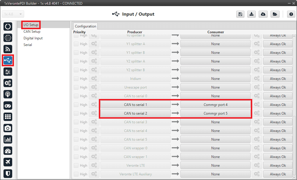
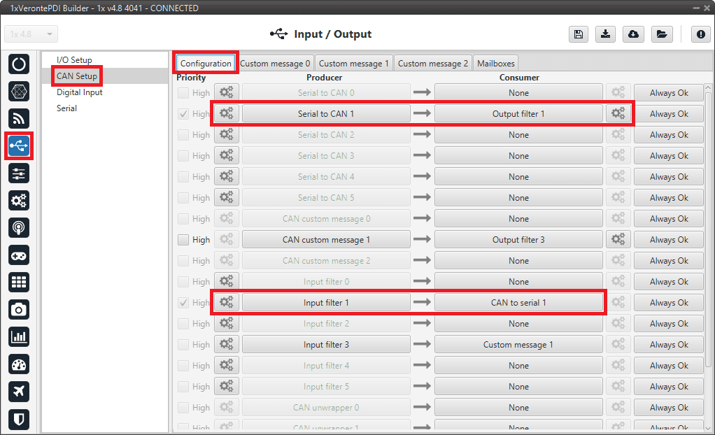
Go to Input/Output menu CAN Setup panel Configuration tab.
-
Connect Serial to CAN 1 to Output filter 1 and Serial to CAN 2 to Output filter 2.
In addition, connect Input filter 1 to CAN to serial 1 and Input filter 2 to CAN to serial 2:
Arbiters communication - CAN Setup configuration -
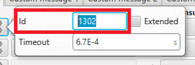
Set for both Serial to CAN 1/2 the same CAN ID: 1302.
Arbiters communication - Serial to CAN 1/2 configuration -
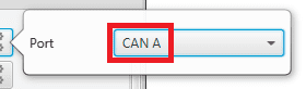
Select for Output filter 1 the CAN A, as this is the CAN of Autopilot 1x that is connected to Arbiter A:
Arbiters communication - Output filter 1 configuration -
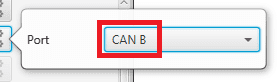
Select for Output filter 2 the CAN B, as this is the CAN of Autopilot 1x that is connected to Arbiter B:
Arbiters communication - Output filter 2 configuration -
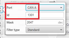
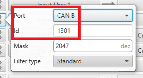
Configure both Input filter 1/2 with CAN ID: 1301.
Select for Input filter 1 the CAN A, as this is the CAN of Autopilot 1x that is connected to Arbiter A:
Arbiters communication - Input filter 1 configuration Select for Input filter 2 the CAN B, as this is the CAN of Autopilot 1x that is connected to Arbiter B:
Arbiters communication - Input filter 2 configuration
Note
This is just an example, users can choose Input filter and Output filter other than 1 and 2.
-
-
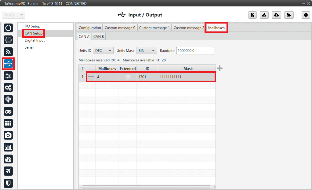
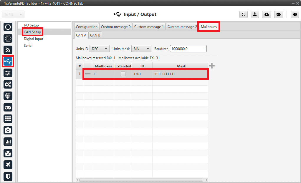
Go to Input/Output menu CAN Setup panel Mailboxes tab.
- Set the Baudrate for both CANs, CAN A: 1 000 000 and CAN B: 500 000.
- Configure at least 10 reception mailboxes with ID 1301 for both CAN A and B:
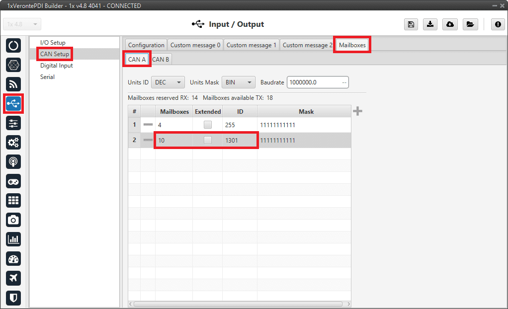
Arbiters communication - Mailboxes configuration: CAN A 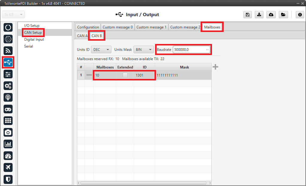
Arbiters communication - Mailboxes configuration: CAN B
CEX/MEX
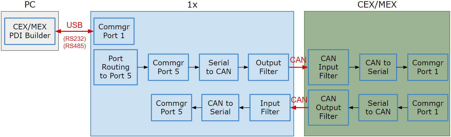
As it is sometimes not possible to connect a CEX/MEX directly to the PC in order to configure it (access CEX/MEX PDI Builder), the Veronte Autopilot 1x is connected to the computer and a connection is made between CEX/MEX and Veronte Autopilot 1x via CAN.
To be able to communicate with CEX/MEX via CAN, the following connection is necessary:
Note
- 1x usually has this configuration by default, but check it out.
- As the steps to be performed in CEX PDI Builder and MEX PDI Builder are exactly the same, only the steps for one of them will be detailed. The interface may differ slightly, but the configuration is the same.
First, connect the CEX/MEX to the Autopilot 1x via CAN. Detailed information on this connection can be found in the:
- CEX connection - Integration examples section of the 1x Hardware Manual.
- MEX connection - Integration examples section of the 1x Hardware Manual.
Then, follow the steps below to make this configuration:
1x PDI Builder side
-
Go to Input/Output menu I/O Setup panel.
Check the connection between the computer and the 1x (usually via USB, but RS232 and RS485 are also possible).
1x PDI Builder - I/O Setup configuration -
Go to Communications menu Ports panel.
Remove Port 5 from the Forward group and add Port 5 to the Route group, with target CEX's Address:
Address = 44000 + Serial number.
The CEX address must be in the range 45000 - 49999.
Note
-
For MEX, the address should look like this:
- Address = 42000 + Serial number.
- The MEX address must be in the range 43000 - 43999.
-
If the theorical address does not work, 999 (unknown) can be used as sometimes the address has not been set in CEX/MEX.
1x PDI Builder - Routing configuration -
-
Go to Input/Output menu I/O Setup panel.
Connect Commgr port 5 to Serial to CAN 1 consumer:
1x PDI Builder - I/O Setup configuration: Serial to CAN Then, connect CAN to serial 1 to Commgr port 5:

1x PDI Builder - I/O Setup configuration: CAN to serial -
Go to Input/Output menu CAN Setup panel Configuration tab.
Connect a Serial to CAN with the right Id (CAN ID 1302) to an Output filter.
In addition, connect an Input filter with the right Id (CAN ID 1301) to a CAN to serial:

1x PDI Builder - CAN Setup configuration 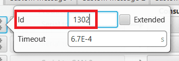
1x PDI Builder - Serial to CAN configuration 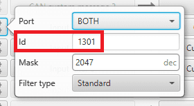
1x PDI Builder - Input filter configuration -
Go to Input/Output menu CAN Setup panel Mailboxes tab.
Finally, configure the reception mailbox with ID 1301, assign at least 4 mailboxes:
1x PDI Builder - Mailboxes configuration
CEX PDI Builder side
Note
This part is already built for CEX default configuration, but the user can check it.
-
Go to Input/Output menu CAN I/O panel Configuration tab.
Connect a CAN Input Filter with the right CAN Address (CAN ID 1302) to CAN to Serial 0.
In addition, connect Serial to CAN 0 with the right CAN Address (CAN ID 1301) to a CAN Output Filter port:
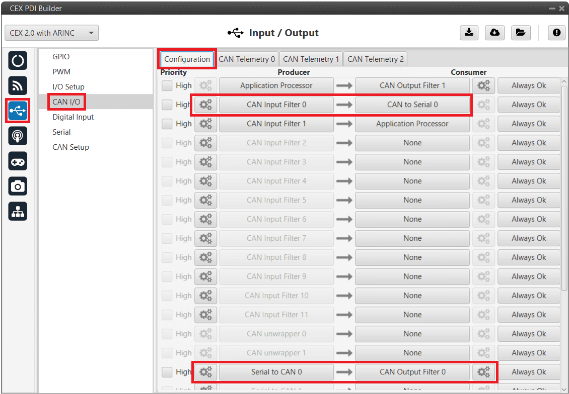
CEX PDI Builder - CAN I/O configuration 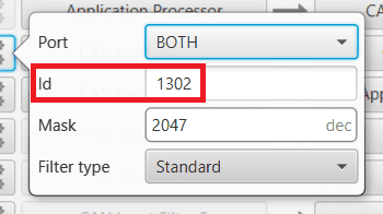
CEX PDI Builder - CAN Input Filter configuration 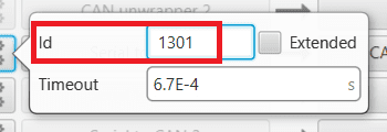
CEX PDI Builder - Serial to CAN configuration -
Go to Input/Output menu I/O Setup panel.
Connect CAN to Serial 0 to any Commgr port, in this case Commgr port 0 is used.
In addition, connect Commgr port 0 to Serial to CAN 0 consumer:
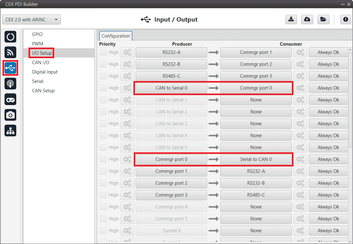
CEX PDI Builder - I/O Setup configuration -
Go to Input/Output menu CAN Setup panel.
Finally, configure the reception mailbox with ID 1302, assign at least 4 mailboxes:
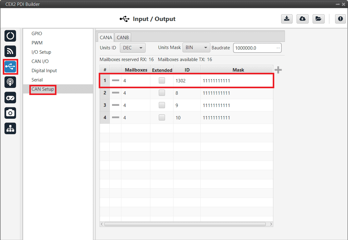
CEX PDI Builder - CAN Setup (Mailboxes) configuration
MC01
In order to communicate a Veronte Autopilot 1x with a MC01 via CAN, the following connection is required:
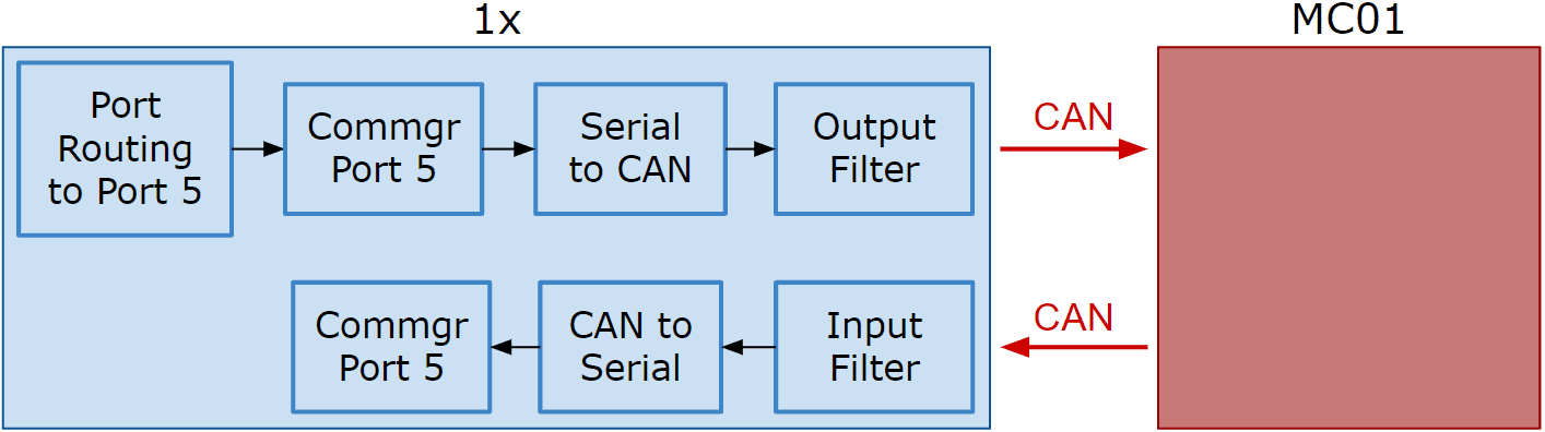
First, connect the MC01 to the Autopilot 1x via CAN. Detailed information on this connection can be found in the MC01 connection - Integration examples section of the 1x Hardware Manual.
Then, the following steps explain how to configure the communication between an Autopilot 1x and a MC01.
MC01 PDI Builder side
- By default, MC01 is configurated with a connection Serial to CAN, with the following Standard CAN IDs:
- Tx CAN Id: 1301
- Rx CAN Id: 1302
1x PDI Builder side
-
Go to Communications menu Ports panel.
Remove Port 5 from the Forward group and add Port 5 to the Route group, with target MC01's Address. This address must be chosen in the destination path of the MC01 (40117 for the example).

1x PDI Builder - Routing configuration -
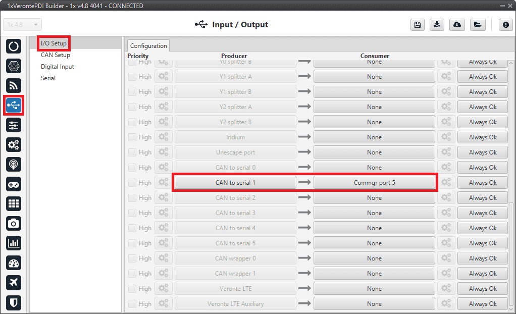
Go to Input/Output menu I/O Setup panel.
Connect the Commgr port 5 to the Serial to CAN 1.

1x PDI Builder - I/O Setup configuration: Serial to CAN Then, connect CAN to serial 1 to Commgr port 5:
1x PDI Builder - I/O Setup configuration: CAN to serial -
Go to Input/Output menu CAN Setup panel Configuration tab.
Connect a Serial to CAN with the right Id (CAN ID 1302) to an Output filter.
In addition, connect an Input filter with the right Id (CAN ID 1301) to a CAN to serial:
1x PDI Builder - CAN Setup configuration 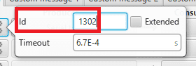
1x PDI Builder - Serial to CAN configuration 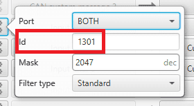
1x PDI Builder - Input filter configuration -
Go to Input/Output menu CAN Setup panel Mailboxes tab.
Finally, configure the reception mailbox with ID 1301, assign at least 1 mailbox:
1x PDI Builder - Mailboxes configuration
MC110/MC24
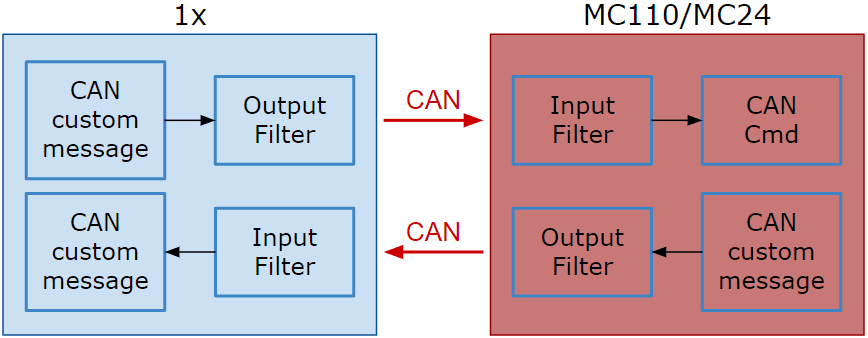
In order to send commands from a Veronte Autopilot 1x to a MC110/MC24 via CAN and vice versa, the following connection is required:
Warning
If users have the Autopilot 1x connected to a PC while commanding via CAN to a MC110/MC24 unit (e.g. when performing test operations), this connection to the PC must be via RS232/485 (recommended RS485), not via a USB connection.
This is because the USB connection between the PC and the 1x may be lost when commanding to the MC110/MC24 unit.
For more information on a connnection via RS232/485 with a Veronte Autopilot 1x, refer to the Wiring connection - Integration examples section of the 1x Hardware Manual.
Note
As the steps to be performed in MC110 PDI Builder and MC24 PDI Builder are exactly the same, only the steps for one of them will be detailed. The interface may differ slightly, but the configuration is the same.
First, connect the MC110/MC24 to the Autopilot 1x via CAN. Detailed information on this connection can be found in the:
- MC110 connection - Integration examples section of the 1x Hardware Manual.
- MC24 connection - Integration examples section of the 1x Hardware Manual.
CAN commands from Autopilot 1x to MC110
Follow the steps below to make this configuration:
1x PDI Builder side
-
Go to Input/Output menu CAN Setup panel Configuration tab.
Connect a CAN custom message producer (in this case CAN custom message 1 is used) to an Output filter consumer, in this example Output filter 3.
In addition, configure the Output filter with the correct CAN Bus, in this example CAN A has been selected:
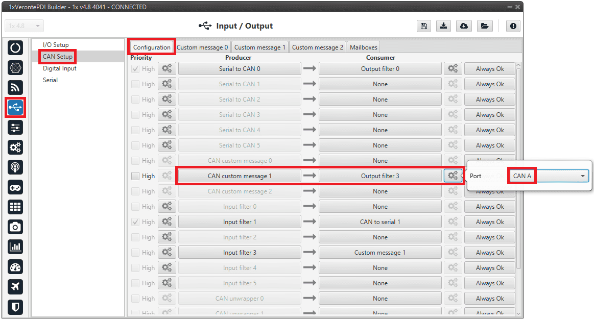
1x PDI Builder - CAN Setup configuration -
Go to Input/Output menu CAN Setup panel Custom message 1 tab (since the producer CAN custom message 1 has been connected to the output filter).
-
Add a new message in TX (as it is for tranmission) with CAN ID 1434. More information on the configuration of CAN messages can be found in the TX/TX Ini Messages (Custom Messages) - Input/Output section of this manual.
-
Next, configure the message to be sent with whatever variable users wish to use to command. The variable should be set to compressed signed 32-bit.
Users should send the values from 0 to max_rpm (or from -max_rpm to max_rpm if negative commands are desired to be allowed).
To do this, it is recommended to control the variable internally as a throttle, for this set the Encode from 0 to 1 (or from -1 to 1 for negative speeds).
And for decode it to rpm values, the Decode parameter must be configured from 0 to max_rpm (or from -max_rpm to max_rpm if negative commands are allowed):
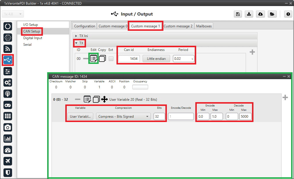
1x PDI Builder - CAN custom message 1 configuration For more information on configuring CAN custom messages, refer to the Custom Messages types - Input/Output section of this manual.
-
Warning
Remember that it is necessary to have at least 1 free mailbox for TX messages.
MC110 PDI Builder side
-
Go to Input/Output menu CAN I/O panel Configuration tab.
Connect an Input filter producer, in this example Input filter 1, to the CAN Cmd consumer.
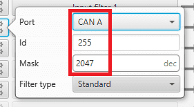
In addition, configure the input filter with the following parameters:
- Port: CAN A
- CAN Id 1434
- Mask: 2047 dec
- Filter type: Standard
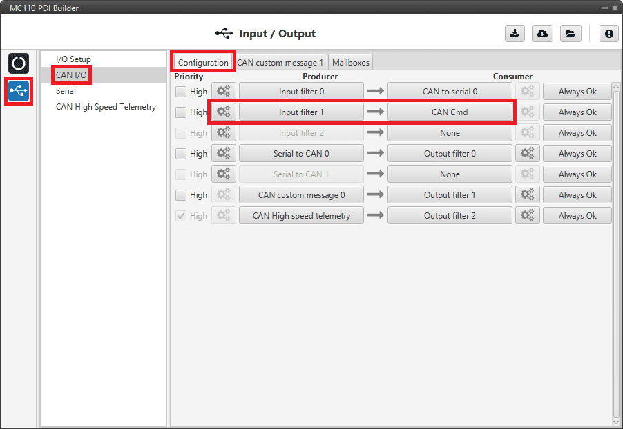
MC110 PDI Builder - CAN I/O configuration 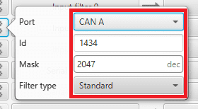
MC110 PDI Builder - Input filter configuration -
Go to Input/Output menu CAN I/O panel Mailboxes tab.
Configure at least 4 reception mailboxes with ID 1434 in the CAN A bus:
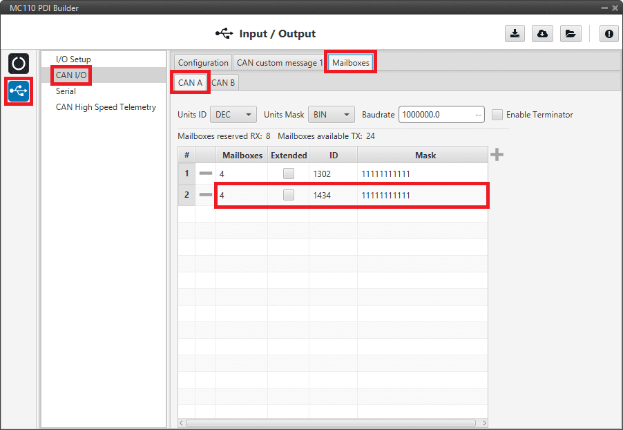
MC110 PDI Builder - Mailboxes configuration -
Go to MC menu FOC Control panel Control Input.
Make sure that m_CAN or m_CAN_PPM mode is selected. For more information on these parameters, refer to the Control Input (FOC Control) - MC section of MC110 PDI Builder user manual.
CAN commands from MC110 to Autopilot 1x
Follow the steps below to make this configuration:
MC110 PDI Builder side
-
Go to Input/Output menu CAN I/O panel Configuration tab.
Connect CAN custom message 0 producer to an Output filter consumer, in this example Output filter 1.
In addition, configure the Output filter with the correct CAN Bus, in this example CAN A has been selected:
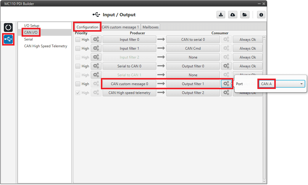
MC110 PDI Builder - CAN I/O configuration -
Go to Input/Output menu CAN I/O panel CAN custom message 1 tab.
Add a new message in TX with the variables the user wishes to send back to Autopilot 1x.
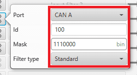
In this example, the message with CAN ID 100 is sending the input command value as well as the board temperature as uncompressed variables.
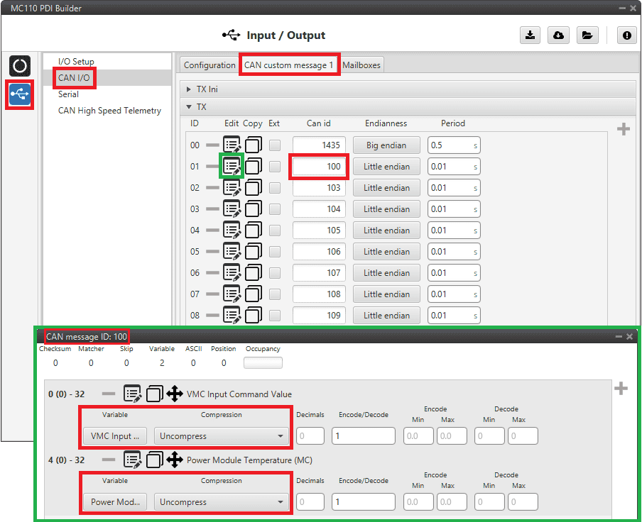
MC110 PDI Builder - CAN custom message 1 configuration For more information on configuring CAN custom messages, refer to the Custom Messages types - Input/Output section of this manual.
Note
If the variables are compressed/encoded on the MC110 side when sent, they must be decompressed/decoded on the Autopilot 1x unit on reception.
1x PDI Builder side
-
Go to Input/Output menu CAN Setup panel Configuration tab.
Connect an Input filter producer (in this case Input filter 3) to a Custom message consumer (Custom message 1 has been selected).
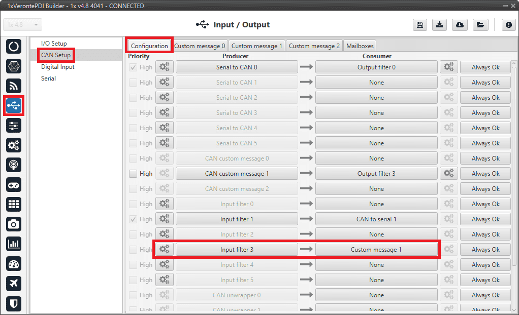
1x PDI Builder - CAN Setup configuration In addition, according to the send message set in the MC110 PDI Builder software, configure the input filter with the following parameters:
- Port: CAN A
- CAN Id 100
- Mask: 1110000 bin
- Filter type: Standard
1x PDI Builder - Input filter configuration -
Go to Input/Output menu CAN Setup panel Custom message 1 tab (since the input filter has been connected to the Custom message 1 consumer).
Users can configure the reception of MC110 variables and store them internally for other uses in the configuration.
To do this, add in RX fields the same messages that have been configured in the MC110 PDI Builder as TX Messages:
1x PDI Builder - Custom message 1 configuration For more information on configuring CAN custom messages, refer to the Custom Messages types - Input/Output section of this manual.
-
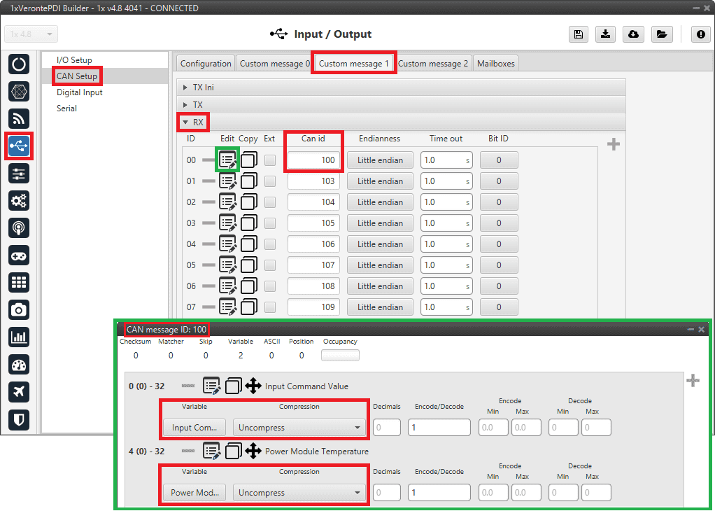
Go to Input/Output menu CAN Setup panel Mailboxes tab.
Finally, configure the reception mailboxes.
In this case, CAN messages with ID 100 and with ID 103 to 109 (8 messages in total) are being sent, which in binary is: 0110 0100 and from 0110 0111 to 0110 1101.
Therefore, 8 mailboxes are configured with ID 01100100 and mask 1110000 in the CAN A bus:
1x PDI Builder - Mailboxes configuration For more information on mailboxes, see the Mailboxes (CAN Setup) - Input/Output section of this manual.
Veronte Gimbal
This section explains the configuration required to control and operate Veronte Gimbal 10z or Veronte Gimbal 30z.
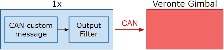
On the one hand, the following diagram illustrates the communication required between a Veronte Autopilot 1x and the Veronte Gimbal to control its movements:
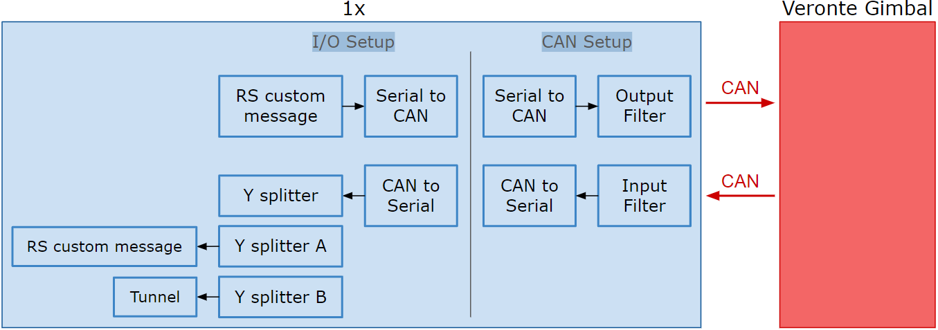
On the other hand, to allow communication between Veronte Autopilot 1x and the video board integrated in the Veronte Gimbal camera the following connection is required:
In the 1x PDI Builder software there is already a template with the required configuration shown in the diagrams above. Users can access it in the following way:
- Open 1x PDI Builder app.
-
Click '1xVeronte' option.
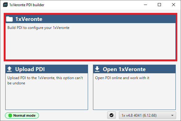
Veronte Gimbal - 1xVeronte option -
In the initial menu of the app, import a configuration from the repo clicking on
 .
.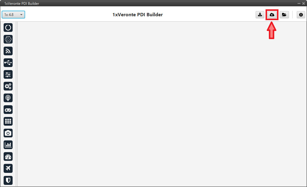
Veronte Gimbal - Import from repo The following window will appear while the templates are being downloaded:
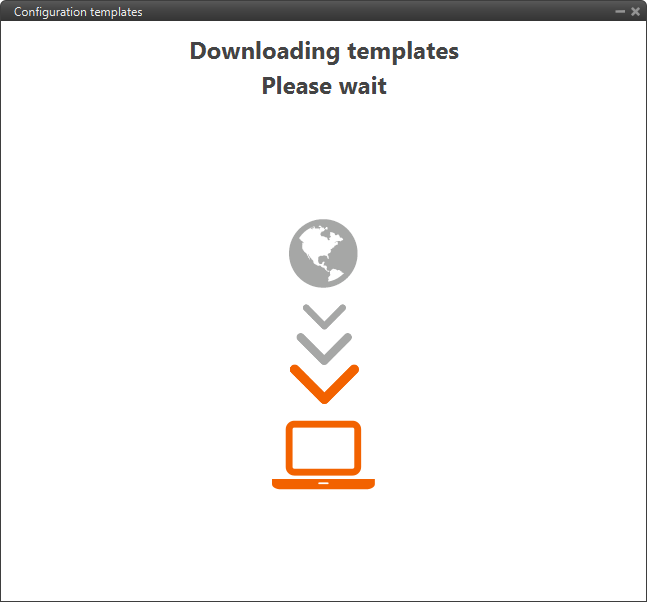
Veronte Gimbal - Downloading templates -
In the templates menu, select the Veronte Gimbal configuration template and press Import to import it to the app.
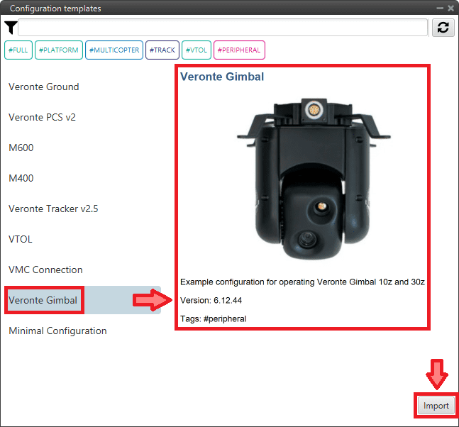
Veronte Gimbal - Veronte Gimbal configuration template
Now, users have to add the Veronte Gimbal control aspects of this configuration template to their own Autopilot 1x configuration.
Controlling Veronte Gimbal movement
Concerning the movement control of the Veronte Gimbal, these are the relevant parts of the configuration:
-
In the Input/Output menu CAN Setup panel Configuration tab.
A CAN custom message producer must be connected to an Output filter consumer. In this example, CAN custom message 0 is connected to Output filter 2 and CAN A bus has been chosen.
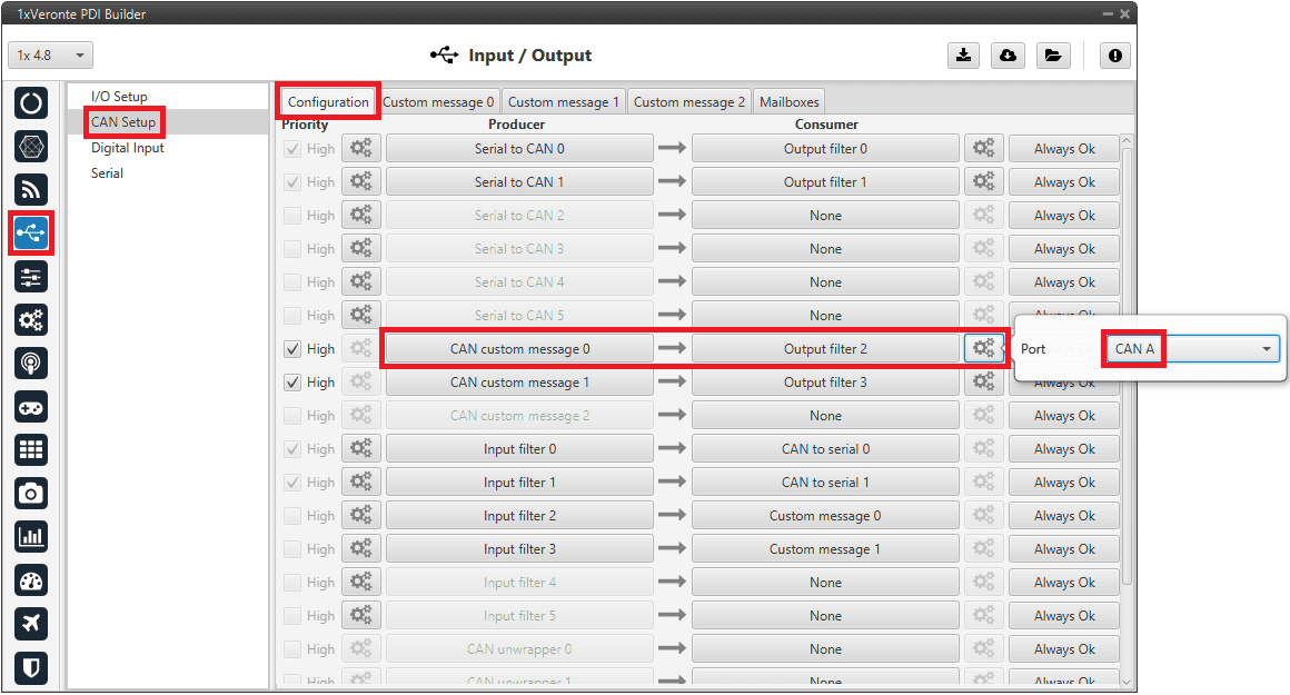
Veronte Gimbal - CAN Setup configuration panel -
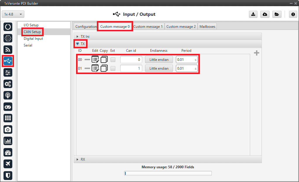
In the Input/Output menu CAN Setup panel Custom message 0 tab (since the producer CAN custom message 0 has been connected to the output filter).
The following parameters must be set for 2 CAN messages on TX (as they are for tranmission) with CAN ID 0 and 1. More information on the configuration of CAN messages can be found in the TX/TX Ini Messages (Custom Messages) - Input/Output section of this manual.
Warning
These specific CAN IDs are entered because they have to match the ones configured in the Gimbal, which are configured by default with these ids.
- Can id: 0 / 1
- Endianness: Little endian
- Period: 0.01 s
Veronte Gimbal - Custom message panel Click on
to access their configuration. This is almost the same for both messages but changing the variable: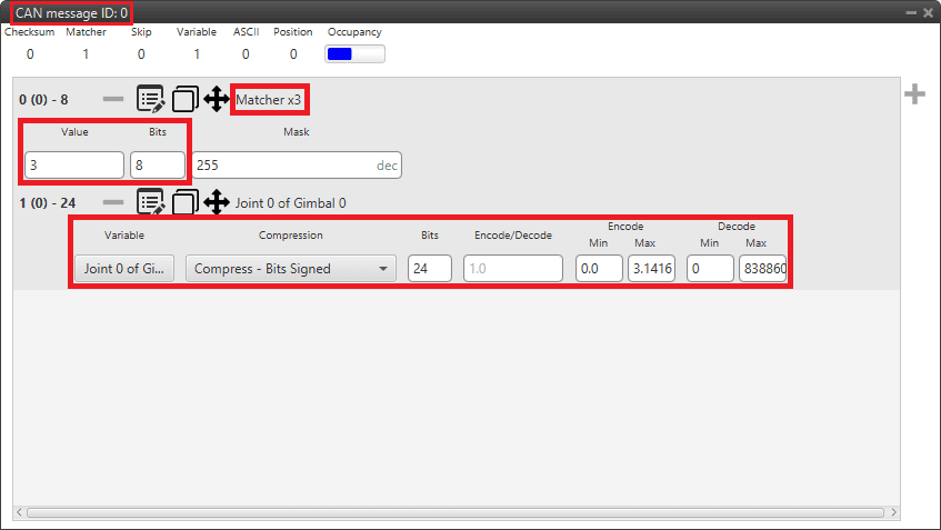
Veronte Gimbal - CAN custom message ID 0 configuration -
Matcher
- Value: 3
- Bits: 8
-
Variable
- Variable: Joint 0 of Gimbal 0
- Compression: Compress - Bits Signed
- Bits: 24
- Encode - Min/Max: 0.0/3.1416
- Decode - Min/Max: 0/8388608
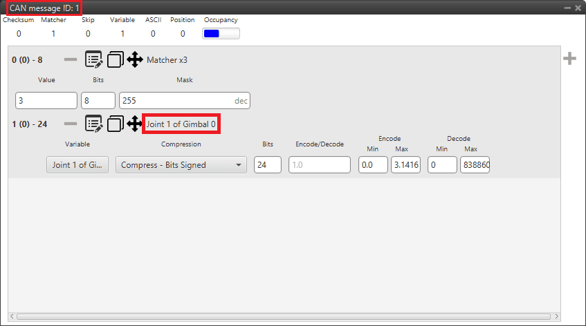
Veronte Gimbal - CAN custom message ID 1 configuration -
Matcher
- Value: 3
- Bits: 8
-
Variable
- Variable: Joint 1 of Gimbal 0
- Compression: Compress - Bits Signed
- Bits: 24
- Encode - Min/Max: 0.0/3.1416
- Decode - Min/Max: 0/8388608
Communication with Veronte Gimbal camera video board
The following are the configuration aspects of the communication with the gimbal camera video board.
CAN commands sent by Autopilot 1x
-
In the Input/Output menu I/O Setup panel.
A RS custom message producer is connected to a Serial to CAN consumer. In this example, RS custom message 0 is connected to Serial to CAN 1.
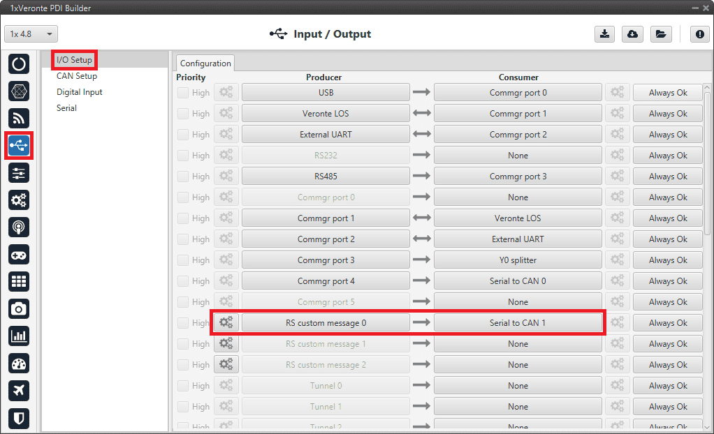
Veronte Gimbal - I/O Setup configuration panel Click on
 to access the RS custom message configuration.
It consists of 4 messages for request variables, i.e. they request information from the video board of the gimbal camera.
to access the RS custom message configuration.
It consists of 4 messages for request variables, i.e. they request information from the video board of the gimbal camera.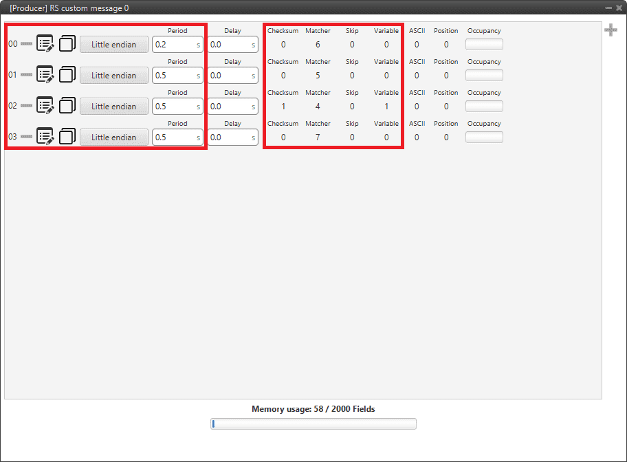
Veronte Gimbal - RS producer custom message configuration Message Endianness Period 00 Little endian 0.2 s 01 Little endian 0.5 s 02 Little endian 0.5 s 03 Little endian 0.5 s -
In the Input/Output menu CAN Setup panel Configuration tab.
A Serial to CAN producer with Id 1304 must be connected to an Output filter consumer. In this example, Serial to CAN 1 is connected to Output filter 1 and CAN A bus has been chosen.
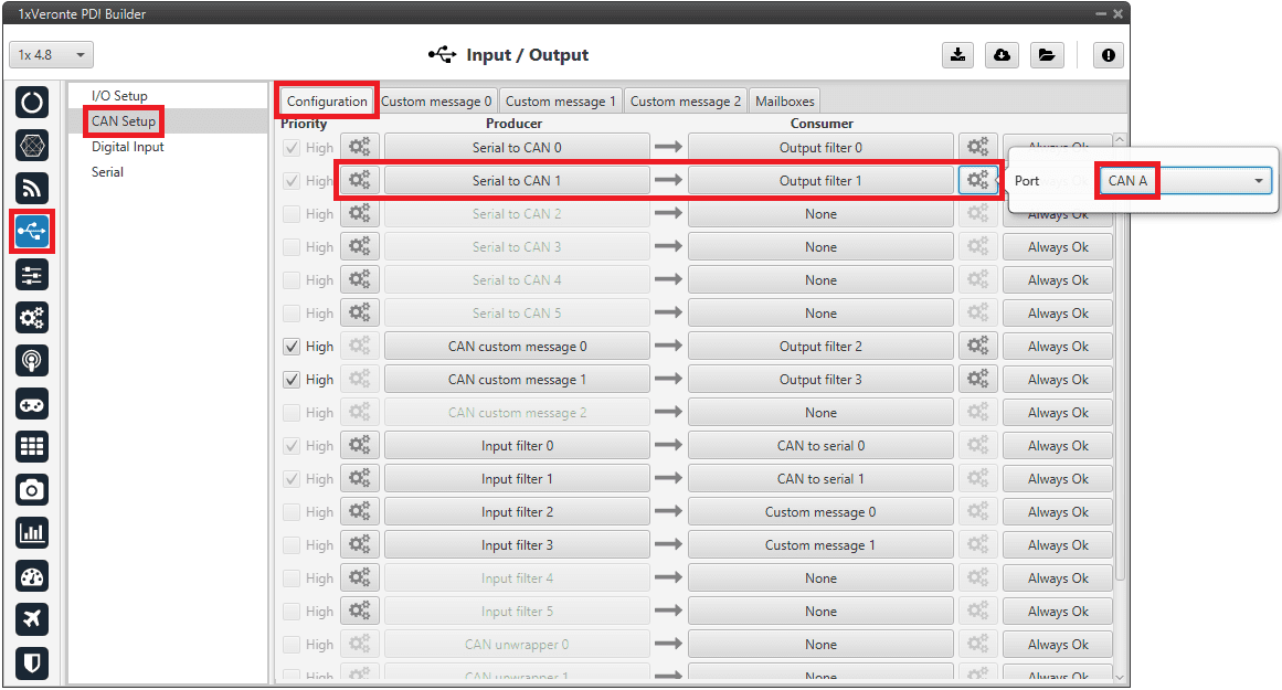
Veronte Gimbal - CAN Setup configuration panel 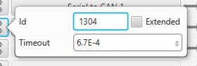
Veronte Gimbal - Serial to CAN configuration
CAN commands received on Autopilot 1x
-
In the Input/Output menu CAN Setup panel Configuration tab.
An Input filter producer with Id 1303 must be connected to a CAN to serial consumer. In this example, Input filter 1 configured to CAN A bus, is connected to CAN to serial 1.
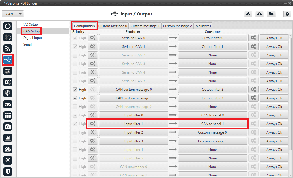
Veronte Gimbal - CAN Setup configuration panel 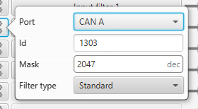
Veronte Gimbal - Input filter configuration -
In the Input/Output menu CAN Setup panel Mailboxes tab.
20 reception mailboxes with ID 1303 are configured in CAN A bus (as the input filter has been configured to CAN A):
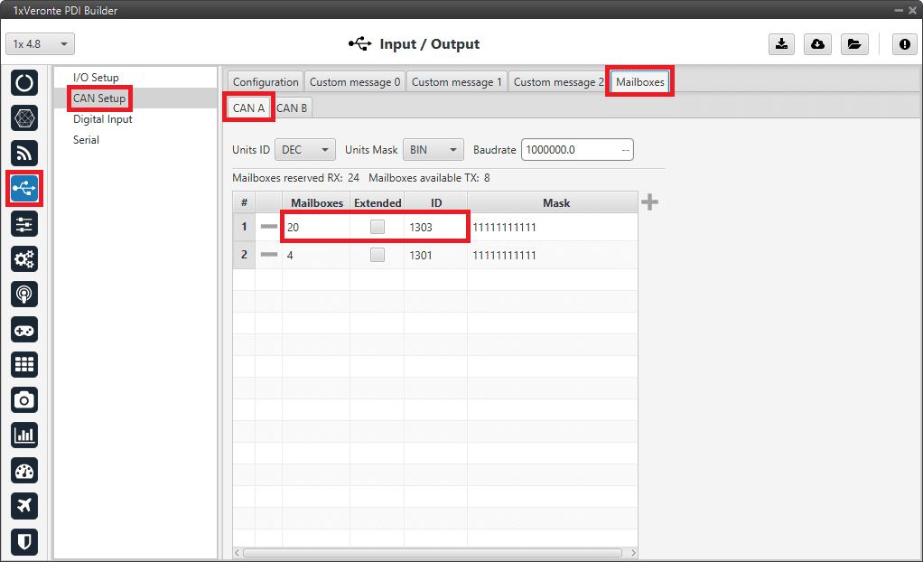
Veronte Gimbal - Mailboxes configuration -
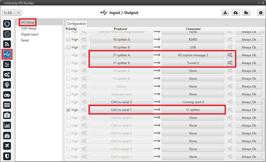
In the Input/Output menu I/O Setup panel.
A CAN to serial producer is connected to a Y splitter consumer. Then, a Y splitter A producer is connected to a RS custom message consumer and a Y splitter B producer is connected to a Tunnel consumer, configured to Address 2 (App 2).
This connection is made in order to read and process the information received from the video board (RS custom message consumer) while sending this information to Veronte Ops. So Autopilot 1x is acting as a tunnel between the video board and Veronte Ops.
In this example, CAN to serial 1 is connected to Y1 splitter, Y1 splitter A to RS custom message 2 and Y1 splitter B to Tunnel 0.
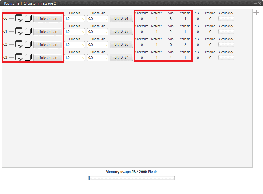
Veronte Gimbal - CAN Setup configuration panel Click on
to access the RS custom message configuration.
It consists of 4 messages to read the video board information from the gimbal camera that has been previously requested.Important
They must be configured as Little endian.
Veronte Gimbal - RS consumer custom message configuration Finally, click on
to access the Tunnel configuration: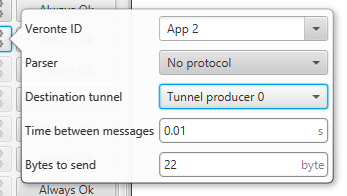
Veronte Gimbal - Tunnel configuration - Veronte ID: App 2
- Parser: No protocol
- Destination tunnel: Tunnel producer 0
- Time between messages: 0.01 s
- Bytes to send: 22 byte
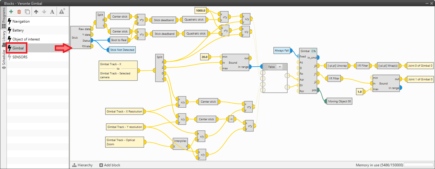
Gimbal block program
Finally, in the Block Programs menu, a Gimbal program has also been created to allow a correct communication between Veronte Autopilot 1x and the video board integrated in the Veronte Gimbal camera.
Warning
Users must add it to their own configuration in exactly the same way.
VSE (Veronte Stick Expander)
To configure the VSE in 1x PDI Builder it is only needed to follow the steps explained in the Ground unit configuration of the General case - PPM Stick integration example.
Important
In the step 1 of that explanation, there is already a transmitter configured with the required VSE configuration, users will find it as Brand: Embention and Model: Stick Expander.
The number of channels configured here must match those set in the VSE application. For more information on this, refer to the Channels - Software Installation section of the Stick Hardware Manual.
Furthermore, as the number of channels is modified, the Brand name will change to Customize.
© 2025 Embention. All rights reserved.