I/O Setup
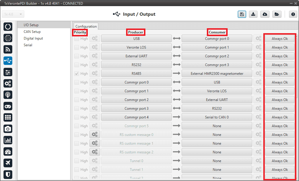
In this panel the user can establish the relationship between a determined signal with a I/O port. This allows users to configure external sensors, messages between 1x units (Tunnel) and custom messages.
-
Priority: Connections between I/O ports can be marked with high priority with this checkbox. If enabled, they will run at high frequency: 1000 Hz.
The following table shows which connections can be selected as high or low priority (marked with S) and which connections are always marked as high (marked with H), so they cannot change to low priority.
Producer\Consumer USB Veronte LOS External UART RS232 RS485 Commgr port 0-5 RS custom message 0-2 Tunnel 0-2 GPS 0-1 RTCM External HMR2300 magnetometer Y 0-2 splitter Iridium Vectornav VN-300 Unescape port Serial to CAN 0-5 CAN unwrapper 0-1 NMEA parser Veronte LTE Veronte LTE Auxiliary External ultrasound USB S S S S S H S S H S S S S S S H Veronte LOS S S S S S H S S H S S S S S S H External UART S S S S S H S S H S S S S S S H RS232 S S S S S H S S H S S S S S S H RS485 S S S S S H S S H S S S S S S H Commgr port 0-5 RS custom message 0-2 Tunnel 0-2 S S S S S S H S S H S S S S S S H GPS 0-1 RTCM S S S S S S H S H H External HMR2300 magnetometer S S S S S S S H S H Y 0-2 splitter A-B S S S S S S H S S H S S S S S S H Iridium S S S S S S H S H S S H Unescape port S S S S S S H S S H S S S S S H CAN to serial 0-5 S S S S S S H S S H S S S S S S H CAN wrapper 0-1 S S S S S S H S S H S S S S S S H Veronte LTE S S S S S S H S S H S S S S S H Veronte LTE Auxiliary S S S S S S H S S H S S S S S H -
Producer: Functions for creating and sending messages.
- Consumer: Functions for receiving and parsing messages
-
Bit: This assigns each connection a bit in a way that allows this connection to be activated/deactivated depending on the status of the selected bit.
By default, the 'Always Ok' bit is set to all connections so that they are always active.
The following are the steps to setting up reception or transmission between ports:
-
Choose the Producer to use.
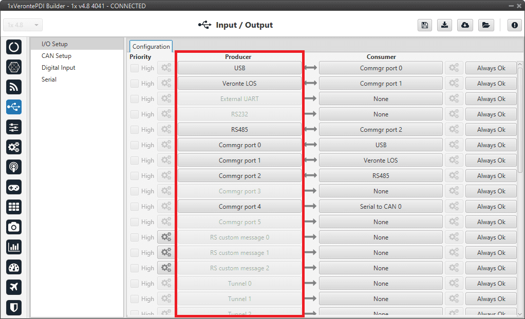
I/O Setup panel - Producers -
To configure the desired Consumer that will be bind to the chosen Producer, it is first required to establish the relationship between them:
- Bind : Unidirectional relationship.
- Bind Bidirectional : Bidirectional relationship. This enables a port to receive or send information.
Note
Once the Consumer has been selected, it is possible to undo the selection by pressing the Clear button.
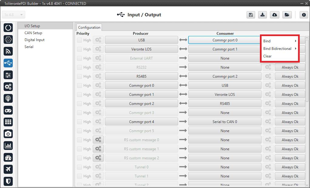
I/O Setup panel - Consumer options -
Select the desired Consumer element.
- (optional) Configure the Bit parameter.
The following I/O ports are available:
| Field | Description |
|---|---|
| USB | USB Port |
| Veronte LOS | Radios |
| External UART |
External UART Port (UART A pin) For more information, see Pinout - Hardware Installation section of the 1x Hardware Manual. |
| RS232 | Serial Port 232 |
| RS485 | Serial Port 485 |
| Commgr port |
COM Manager ports send and receive VCP messages. VCP is the protocol used by Veronte products to communicate. For more information, read the VCP user manual. |
| RS Custom Message | This allows user to send/receive a serial custom message, see Serial Custom Messages. |
| Tunnel | Creates a bidirectional bridge between two devices, see Tunnel. |
| GPS RTCM | This allows the user to send/receive RTK information from GND unit to AIR unit. |
| External HMR2300 magnetometer | External magnetometer sensor, see the Magnetometer Honeywell HMR2300 - Integration examples section. |
| External ultrasound | External ultrasound sensor, see the Internest - Sensors section. |
| Y Splitter | Used to split a signal into 2 |
| Iridium | Iridium communication, see the Iridium - Communications section. |
| Vectornav VN-300 |
Vectornav VN-300 is an external IMU. For more information, see the Vectornav VN-300 - Integration examples section. |
| Unescape port | This allows user to reconstruct a byte stream with an escape logic, see Unescape port. |
| CAN to serial / Serial to CAN | Serial to CAN sends serial streams over a CAN Bus / CAN to serial undoes the transformation 'Serial to CAN', see the CAN to serial/Serial to CAN section. |
| CAN wrapper / CAN unwrapper | CAN wrapper sends CAN streams over a serial Bus / CAN unwrapper undoes this transformation, see the CAN wrapper/CAN unwrapper section. |
| NMEA Parser | NMEA 0183 messages parser, see NMEA Parser. |
| Veronte LTE |
4G Connection. For more information, see the
4G - Communications section.
Warning
The configuration for a Veronte Autopilot 1x hardware version 4.8 is different than for one with hardware version 4.5.
If the user has any questions, please contact the support team following the user's
Joint Collaboration Framework.
|
| Veronte LTE Auxiliary |
Warning
Reserved port. |
More information about some elements can be found in the following sections.
Serial Custom Messages
Warning
-
Autopilot 1x has a serial limitation of 64 vectors (fieldset) per Custom.
In addition, there is a limit shared with all Customs, including CAN Custom Messages:
- Maximum number of vectors (fieldset): 104
- Maximum number of fields: 2000
It is possible to configure the messages sent/received through the serial port and its conversion to system variables by selecting the option RS Custom message and configuring the I/O port.
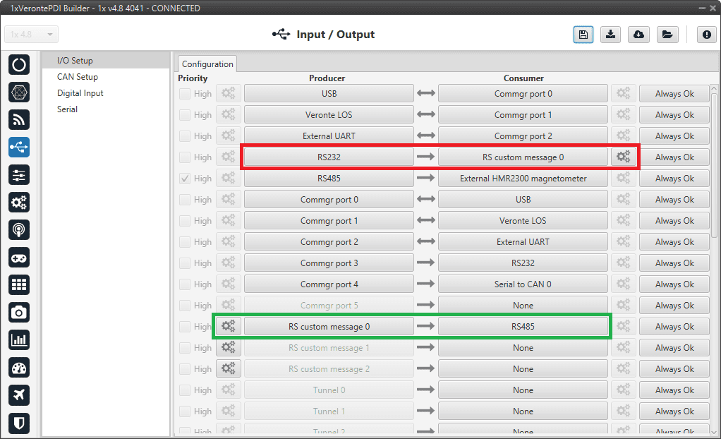
In the image above two possible configurations using an RS Custom Message can be seen. The 'red' one is configured to receive a given message from an RS232 serial port and the 'green' is used to send a RS Custom Message through an RS485 serial port. It is also possible to use the same RS Custom Message for both tasks if the bidirectional relationship is selected (the arrow indicates this (Bind Bidirectional )).
To configure a RS Custom message, the user must follow the next steps:
-
Press the configuration button (
 icon) and a pop-up window will be displayed.
In this window press the
 icon to add a custom message, the user can choose between System variables, ADSB Vehicle or External Sensor.
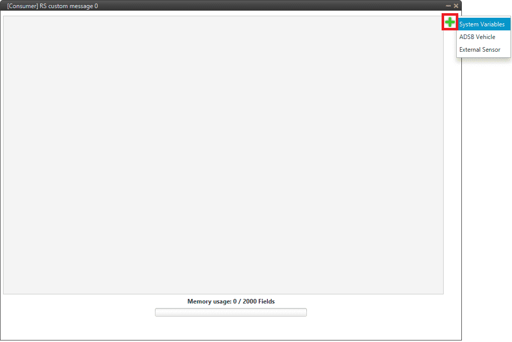
Serial Custom Message configuration Note
The difference between choosing System Variables, ADSB Vehicle or External Sensor is that when the user selects Variable as the custom message type, only system variables will appear when System Variables is selected, only ADSB variables when ADSB Vehicle is selected and only variables related to external sensors if External Sensor is selected.
-
When it is already added, the following options are available to configure a custom message:
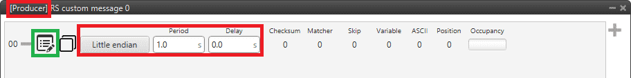
Producer RS Custom Message configuration 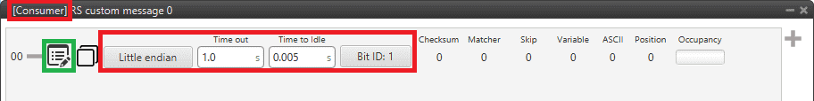
Consumer RS Custom Message configuration -
Endianness: Depending on the order in which the device issue the message, it is possible to select:
- Big endian: Set the value from left to right.
- Little endian: Set the value from right to left.
- Mixed endian: Some devices use this format. If users need to configure it, please contact the support team (create a ticket in the customer's Joint Collaboration Framework; for more information, see Tickets section of the JCF manual).
-
Period/Time out: This option has a dual role depending on if it is used to transmit or receive data.
- Period - Producer: It is the inverse of the send frequency.
- Time out - Consumer: This is the threshold time between receptions to consider that the message is not being received correctly.
-
Delay/Time to Idle: The purpose of this feature is ensuring half-duplex communication. This option has a dual role depending on if it is used to transmit or receive data.
-
Delay - Producer: After sending the message, the Serial bus will be disabled for this amount of time in order to allow half-duplex communication.
Warning
Delay time must not be longer than the specified period, since this will result in out-of-order message sending.
-
Time to Idle - Consumer: This is the time Autopilot 1x waits before discarding partially parsed bytes.
-
-
Bit ID: This option is only available when a message is configured as Consumer. The user bit selected in Bit ID box will be true if the message is being received correctly.
Warning
Pay attention that the user bit selected in Bit ID is not in use for another task.
-
-
To create the structure of the message, click on the edit message button (
 icon) and then press the icon to add fields to it.
The following type of messages are available to configure a structure: Variable, Checksum, Matcher, Skip, Parse ASCII and Position.
icon) and then press the icon to add fields to it.
The following type of messages are available to configure a structure: Variable, Checksum, Matcher, Skip, Parse ASCII and Position.The configuration of each structure is covered in the Custom Messages types - Input/Output section of this manual.
Warning
Before configuring any message, user has to know the structure it has to have according to the device that is connected to the port. Each device may have a different message structure when it sends or receives information.
In addition, the steps to be followed from the moment a Serial message arrives at or is sent from the Autopilot 1x are described in the Serial communication - Integration examples section of this manual.
To check serial messages transmission, see the Debug serial messages transmission - Troubleshooting section of this manual.
Tunnel
It is possible to configure a Tunnel, which is a bidirectional bridge between 1x units that communicate to each other sharing information about an external device connected to the Serial or Digital port.
Imagine that it is desired to have a button connected to the 1x air unit to launch a parachute. It is not possible to physically connect the button because the air autopilot is in the flying platform, so a different option is needed. Here is where the tunnel becomes useful. The button could be connected through the Serial or Digital port to the 1x ground unit, and then the signal is sent through the tunnel to the air unit. With this configuration it would be like if the button were physically connected to the aircraft.
Let's consider the following image:
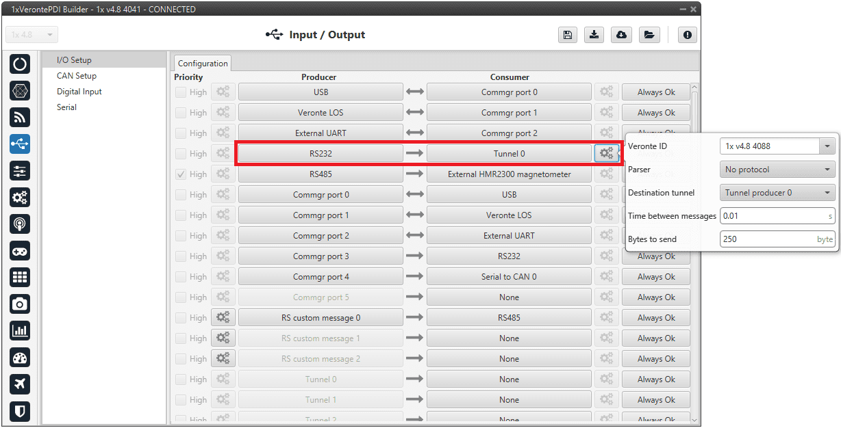
In the image above there is a device connected to the RS232 (Producer) and there is a Tunnel (Consumer) which sends that information to other Autopilot 1x with a determined ID. On the other hand, 1x air unit has to be configured to receive the signal sent by other device. In that case the Producer will be Tunnel and Consumer will be the port or destination tunnel where the device is connected.
The options available when configuring Tunnel as Consumer are:
-
Veronte ID: Enter the address that will receive the information. The following options are the most common:
- App 2: Veronte applications address.
- Broadcast: All units on the network. Select this option for a generic configuration.
-
Address of a specific Veronte unit, it can be a 1x, a 4x, a CEX, etc.
For more information on the available addresses, see List of Addresses - Lists of interest section of the 1x Software Manual
-
Parser: The user can choose protocol to parse message data. The options available are:
- No protocol
- RTCM3
- CANserial
-
Destination tunnel: Number of port is used to avoid mistakes and identify a Tunnel when using more than one, Tunnel 0, 1 and 2 are available.
- Time between messages.
- Bytes to send: Sets the message size to send.
When configuring Tunnel as Producer (i.e. on the unit that receives the information), no configuration is required. It is only necessary to connect it to a Consumer, usually to a serial port.
Unescape port
To understand what unescape is, the user must first understand what an escape byte is.
Let's consider that there is a protocol that defines a 'Flag' as the start and end byte of the frame. In case the flag or an escape value appears in the frame data, and in order not to misinterpret the message, an escape byte or the same value repeated will be added before them so that, at the time of parsing, it will be reconstructed with the original byte.
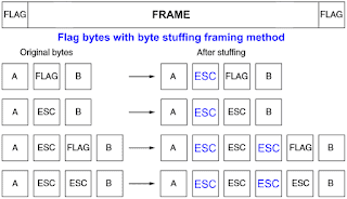
In 1x PDI Builder, an Unescape port has been implemented to allows to reconstruct a byte stream with an escape logic.
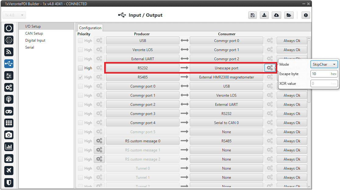
Two modes of escapes are supported:
- SkipChar: The unfolding of the value to be escaped, the byte to escape has been repeated in the message.
- SkipAndXOR: In this case, the escape byte is entered first and then the value to escape (i.e. the value to escape XOR escape byte).
In addition to this, two more options are available in this pop-up window:
- Escape byte: Escape byte added.
- XOR value: Only available when 'SkipAndXOR' option is selected.
CAN to serial/Serial to CAN
The CAN to serial and Serial to CAN ports allow Serial communication via CAN bus. For this, Serial to CAN creates a message with a specific sequence which ensures the transmission of serial message data; and CAN to serial undoes this transformation to a regular serial message.
To ensure proper communication using the "Serial over CAN" protocol, the following structure must be adhered to:
-
Frame Structure
- Each CAN frame must begin with a sequence number in the first byte (Byte 0).
- The sequence number must increment monotonically and wrap back to zero after reaching 255.
- The remaining bytes of the frame (Byte 1 to Byte 7) contain the data payload.
-
Frame Sequence Example
The following example illustrates a correctly structured frame sequence:
Byte 0 (Sequence) Byte 1 Byte 2 Byte 3 Byte 4 Byte 5 Byte 6 Byte 7 0x34 0xA0 0xA1 0xA2 0xA3 0xA4 0xA5 0xA6 0x35 0xA7 0xA8 0xA9 0xAA 0xAB 0xAC 0xAD 0x36 0xAE -
Deserialization Process
- Upon reception, the payload must be reconstructed by concatenating the data bytes from sequential frames.
- The expected output of the deserialized payload will be: 0xA0, 0xA1, 0xA2, 0xA3, 0xA4, 0xA5, 0xA6, 0xA7, 0xA8, 0xA9, 0xAA, 0xAB, 0xAC, 0xAD, 0xAE
Warning
- If a jump of more than 8 in the sequence number is detected, it will be assumed that some data has been lost and the internal counter will be restarted to the new (higher) sequence number to realign the data stream.
For further details on how to use these ports, consult the Serial messages transmission via CAN bus - Integration examples and the Serial messages reception via CAN bus - Integration examples sections of the present manual.
CAN wrapper/CAN unwrapper
The CAN wrapper and CAN unwrapper ports allow CAN communication via serial. For this, CAN wrapper creates a message with a specific sequence which ensures the transmission of CAN message data; and CAN unwrapper undoes this transformation to a regular CAN message.
The structure of the messages sent/received by the CAN wrapped and CAN unwrapped respectively is the following:

| Content | Size |
|---|---|
| Matcher: 0xCA | 1 byte |
| CAN ID | 4 bytes |
| Data size | 1 byte |
| Data | N bytes |
| CRC | 2 bytes |
For further details on how to use these ports, consult the CAN messages transmission via serial - Integration examples and the CAN messages reception via serial - Integration examples sections of the present manual.
NMEA Parser
NMEA Parser is another way to add an external GNSS device. This consumer allows to receive NMEA 0183 messages and parses them directly. The NMEA Parser configuration menu includes the following parameters:
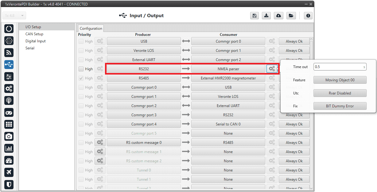
- Time out: Defines the period of incoming information from the external system.
- Feature: Variable extracted from the message defining the GNSS position. Usually Moving Object variables are used.
- Utc: Variable extracted from the message defining the UTC.
- Fix: Data provided by the external device which is important to know the status of the positioning.
Once the NMEA message has been parsed, the variables used for Fix and Feature can be selected in the GPS External configuration of the GNSS block as Fix Bit and GPS Position. For more information about this configuration, see Sensors blocks - Block Programs section of this manual.
© 2025 Embention. All rights reserved.