Datalinks
LOS
Warning
The internal radio of Veronte Autopilots 1x depends on the hardware version, so the user should check the internal radio according to the hardware version of his Autopilot 1x:
Digi internal radio
Configuration
This section describes the necessary configuration for 1x PDI Builder and the Digi radio software (XCTU) to allow a correct communication between Veronte Autopilot 1x and its internal Digi radio.
To configure the communication between Autopilots 1x and their internal Digi radios, apply the following steps to each one (1x air and 1x GND/PCS unit):
- Connect the Autopilot 1x to a computer with Veronte Link, read its user manual to use it.
Configuration in 1x PDI Builder
-
Go to Input/Output menu I/O Setup panel.
The configuration of this panel is going to be temporarily modified in order to allow the setting up of a tunnel between the autopilot and the radio, i.e. the current configuration will have to be further re-established. For this reason, it is necessary that the user first annotates the configuration of USB, Veronte LOS and the ports to which they are connected. The following image shows an example.
Note
It is recommended to take a screenshot for this step.
Warning
Although the connection with Autopilot 1x will be lost via USB, users can still "see" the autopilot via serial (RS232 or RS485). For this purpose, the bidirectional RS232 or RS485 connection must not be modified.
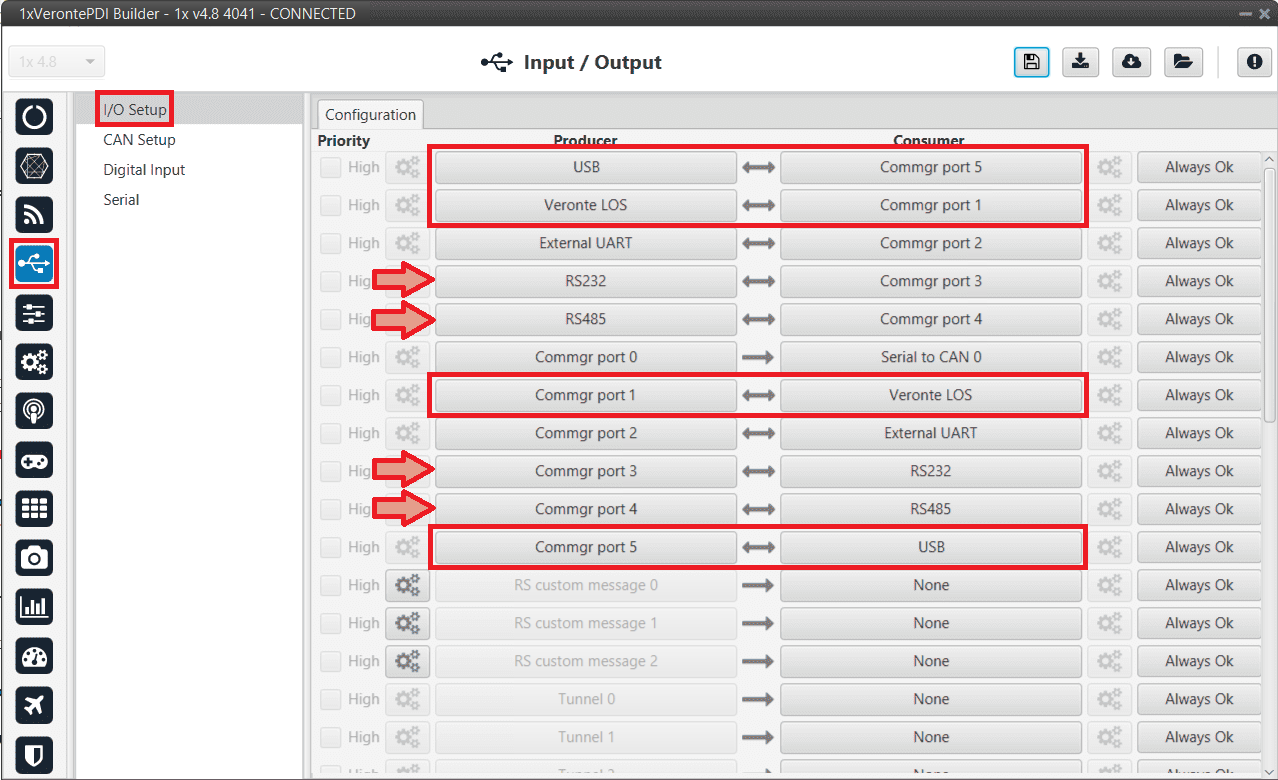
Digi internal radio - Example of configuration of USB and Veronte LOS ports -
Change the port which USB producer is connected to and select Veronte LOS as consumer.
USB and Veronte LOS must have bidirectional communication .
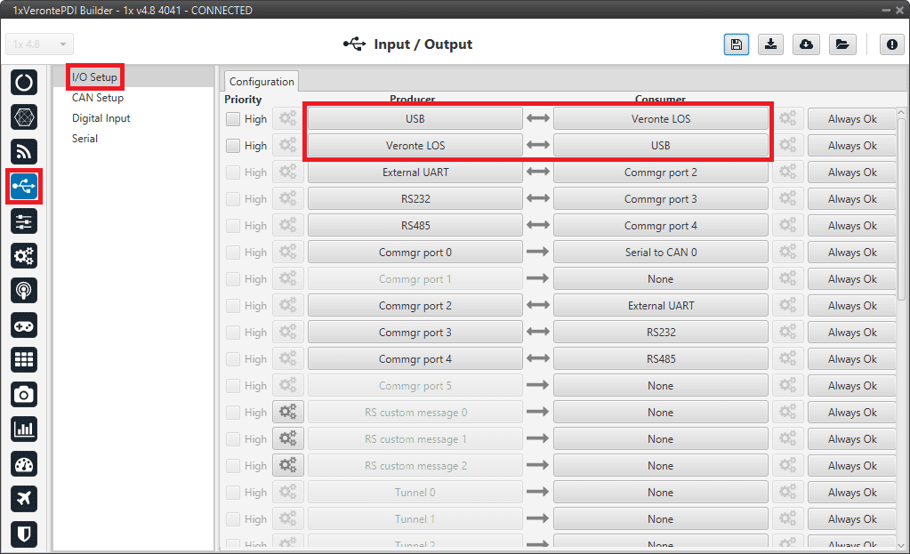
USB ↔︎ Veronte LOS -
Go to Input/Output menu Serial panel Veronte LOS tab.
It is important to know which baudrate is configured for the Veronte LOS serial port in order to match it with the one configured in the Digi radio.
By default, the baudrate configured in 1x PDI Builder is set to 115200.
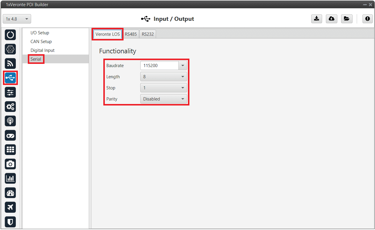
Digi internal radio - Veronte LOS baudrate -
Click on
 to apply changes to the Autopilot.
Warning
The communication between computer and Autopilot 1x will be disconnected, since the autopilot is working as a tunnel between computer and radio. The computer will be communicating only with the Digi radio.
-
Wait for the device to disconnect and close Veronte Link. If the user does not close it, XCTU software will not be able to detect the radio as the COM is being managed by Veronte Link, and the following error message will appear:
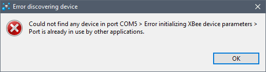
Digi internal radio - XCTU error message Important
Remember that to completely close the application the user must close it from the windows system tray.

Close Veronte Link
Configuration in Digi radio software
-
Download and install XCTU (Digi radio software).
-
Build a configuration for 'air' or 'GND' in XCTU:
The integrated radio is the model DIGI-XBEE3 XB3-24Z8UM. For more information about how to configure it, read the XCTU User Guide.
The following table shows which parameters can be configured. The rest of parameters should remain as default.
DIGI Parameter Description PL Transmit power (100 mW) ID Network address PAN ID DD Device type identifier BD UART baud rate (115200) RR Retries (minimum 5) CH 2.4 GHz channel to send MM MAC mode, 802.15.4 with Digi header for discovery and package duplication CA Clear channel threshold as dBm EA Ack failures EC Failure to send due to excess energy in channel Note
Radios to pair must have matching PAN IDs.
Warning
Check that the baudrate of the radio matches the baudrate configured in 1x PDI Builder. If it is not the same, change one of them to match. Remember that Veronte LOS baudrate must not exceed 115200, as this may compromise proper communication.
-
Only for Autopilots 1x implemented in a 4x
Digi radios are able to create a network and talk to each other, even if they are configured as endpoint. This is a problem, as it leads to radio channel overload.
To prevent this problem, the destination addresses must be configured so that the ground station transmits in broadcast and each air unit transmits only to the ground.
The following table shows how to configure air and ground units in XCTU:
Radio Parameter Configuration Ground MY 16-bit Source Address FFFFDH Destination Address High 0DL Destination Address Low FFFFAir MY 16-bit Source Address FFFFDH Destination Address High SH of the ground radio DL Destination Address Low SL of the ground radio 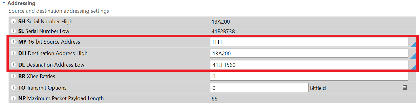
Digi internal radio - Air radio configuration example 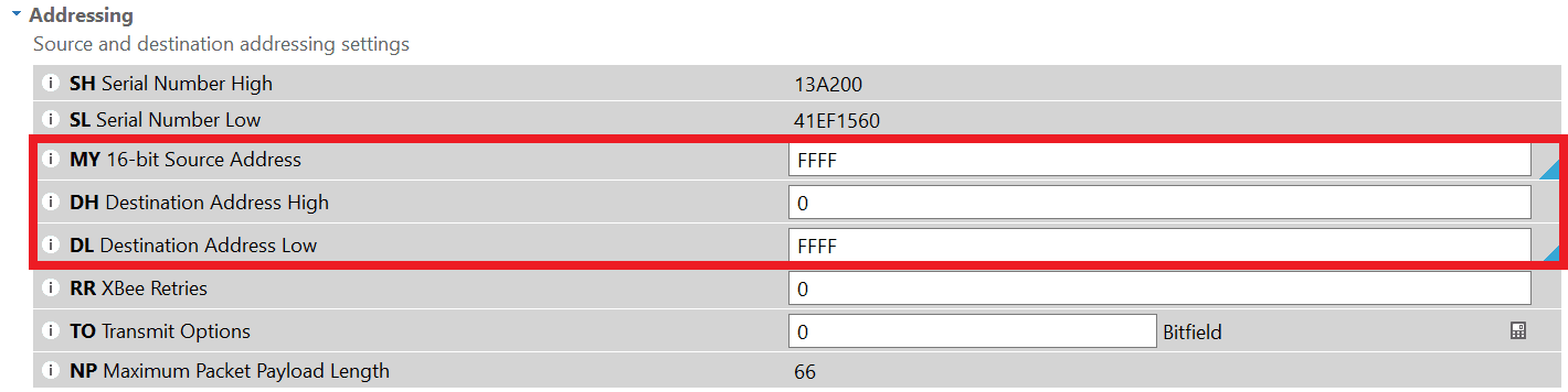
Digi internal radio - Ground radio configuration example Error
If the configured device is not an Autopilot 1x implemented in a 4x, the above parameters must be set to null values.
-
After configuring the radio, the communication between computer and Autopilot 1x should be restored. To do it, force the maintenance mode.
Configuration in 1x PDI Builder
-
Go to Input/Output menu I/O Setup panel.
Finally, after configuring the Digi radio in its software, restore the annotated USB and Veronte LOS configuration (step 2).
If communication between the Digi radio and the Veronte Autopilot 1x is lost after the entire radio setup process described above, or later during operation, please refer to the Communication lost with internal Digi radio - Troubleshooting section of this manual.
Operational range
The following table is a reference of the functional range for each telemetry load (it may be affected by enviromental conditions):
| Frequency | |||
|---|---|---|---|
| Load | 5 Hz | 10 Hz | 20 Hz |
| Low (Half telemetry vector) | > 700 m | 500 m | 300 m |
| Medium (one telemetry vector) | > 700 m | 100 m | 80 m |
| High (two or more telemetry vectors) | 300 m | 80 m | X |
Note
Telemetry vectors are structured messages with up to 255 bytes of data. To know more about them, read Message structure section of VCP user manual.
Microhard internal radio
This section describes the necessary configuration that must be performed in 1x PDI Builder and 1x PDI Calibration to allow a correct communication between Veronte Autopilot 1x and its internal Microhard radio.
To configure the communication between Autopilots 1x and their internal Microhard radios, apply the following steps to each one (air and GND unit):
- Connect the Autopilot 1x to a computer with Veronte Link, read its user manual to use it.
Configuration in 1x PDI Builder
-
Go to Input/Output menu I/O Setup panel.
Since the configuration of this panel is going to be modified temporarily, i.e. the current configuration will have to be re-established, just to be able to set up a tunnel between the autopilot and the radio. It is necessary that the user first annotates the configuration of Veronte LOS, Tunnel and the ports to which they are connected.
The following image shows an example.
Note
It is recommended to take a screenshot for this step.
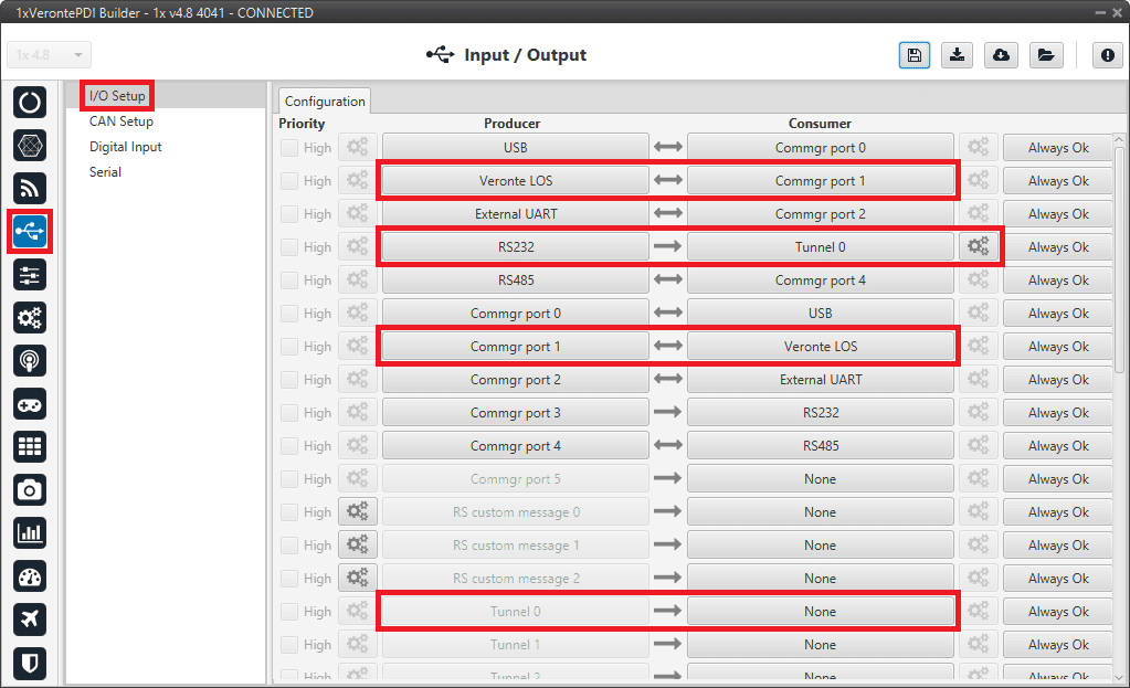
Microhard internal radio - Example of configuration of Veronte LOS port -
Change the port which Veronte LOS producer is connected to and select a Tunnel as consumer, in this example Tunnel 0 has been selected.
Veronte LOS and Tunnel 0 must have bidirectional communication .
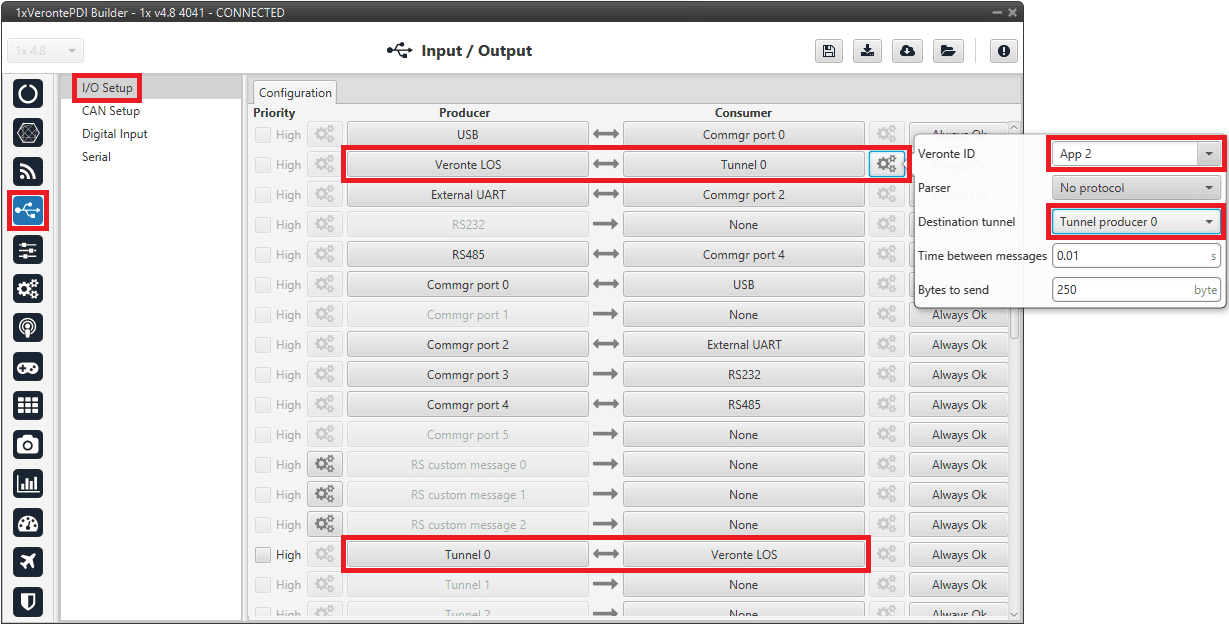
Veronte LOS ↔︎ Tunnel 0 -
Click on
to apply the changes to the Autopilot 1x.
Configuration in 1x PDI Calibration
-
In 1x PDI Calibration, go to Terminal panel.
To set up the Microhard radio, the 1x PDI Calibration software provides a Microhard wizard to assist the user in setting up the radio.
Please refer to the Terminal and Microhard setup helper sections of the 1x PDI Calibration user manual.
Configuration in 1x PDI Builder
-
Go to Input/Output menu I/O Setup panel.
Finally, after configuring the Microhard radio in 1x PDI Calibration, restore the annotated Veronte LOS and Tunnel 0 configuration (step 2).
-
Click on
to apply the changes to the Autopilot 1x.
External radios
This section describes the required configuration to be performed in 1x PDI Builder to allow a correct connection between Veronte Autopilot 1x and any external radio.
External radios compatible with the Autopilot 1x, such as Microhard, DTC, Digi, Silvus, SDL and XDL24 (Embention external datalinks, contact sales@embention.com for more information).
After configuring the external radio in the corresponding software, follow the steps below:
-
Go to Input/Output menu Serial panel RS232 tab.
Check that these parameters are the same as the parameter values previously set in the external radio.
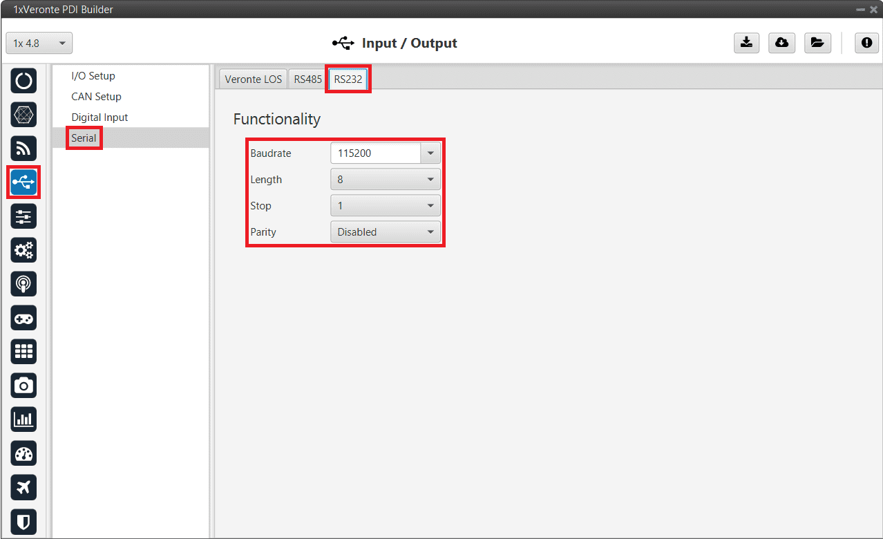
External radios - RS232 port configuration -
Go to Input/Output menu I/O Setup panel.
RS-232 has to be configured as a bidirectional commgr port.
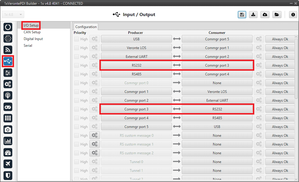
External radios - I/O Setup configuration
Note
These settings have to be made in both Autopilot 1x units (GND and AIR).
© 2025 Embention. All rights reserved.