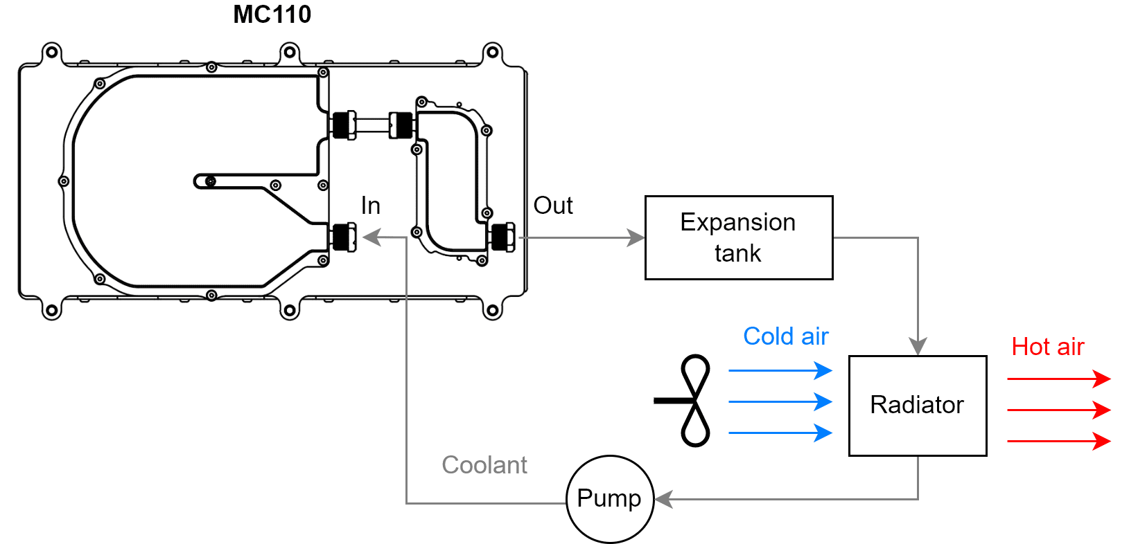
Simplified Cooling Circuit Design
This subsection explains how to size a specific layout of cooling design, so the user does not have to calculate any parameters. This layout is intended for one single MC110. In case of desiring to use a different layout or to refrigerate multiple controllers with a single circuit, read the Advanced Cooling Circuit Design.

Basic diagram of cooling circuit
Each cooling element must accomplish the following requirements:
Pump
Flow rate: 6 l/min.
Minimum pressure: 0.5 bar.
Activity: always on (while MC110 is on).
Pipes connected to cold plate
Water-glicol resistant
Able to join with the following ports:

Port diamaters (mm)
Tip
For cold plate connections, it is recommended to use fluoropolymer tubing with 8 mm of outside diameter and 6 mm of internal diameter.
Coolant
Mixture water-glycol at 50 %, in order to have a freezing temperature below operating conditions.
Radiator
Radiator thermal conductivity (which is related to size) depends on motor power, switching frequency and battery voltage. Depending on each situation, the following tables show the minimum heat transfer of the required radiator.
Heat transfer for 10 kHz switching frequency (W/ºC)
Motor power (kW)
Battery voltage
800 V
550 V
100 V
15
50
50
150
30
100
100
*
45
100
150
*
60
150
150
*
75
150
200
*
95
200
200
*
110
200
200
*
Heat transfer for 16 kHz switching frequency (W/ºC)
Motor power (kW)
Battery voltage
800 V
550 V
100 V
15
50
50
150
30
100
100
*
45
150
150
*
60
150
150
*
75
200
200
*
95
200
200
*
110
250
250
*
Heat transfer for 22 kHz switching frequency (W/ºC)
Motor power (kW)
Battery voltage
800 V
550 V
100 V
15
100
100
150
30
100
150
*
45
150
150
*
60
200
200
*
75
200
200
*
95
250
*
*
110
*
*
*
Warning
*: These situations involve an intensity higher to 250 A or overheating.
Tip
The generated heat by the MC110 increases with switching frequency and motor power. But it decreases with battery voltage.
Be careful with the change of tube sections. If the coolant transitions from a small to a large section, air bubbles may remain.
