Technical
Part List
Veronte MC110 includes the following connectors:
Veronte Harness of 24 pins for user connector. Embention reference: P001634.
Veronte Harness of 16 pins for sensor connector. Embention reference: P001635.
Main Features
IP68 Waterproof
Voltage: between 100 and 550 V
Configuration parameters: for reduced power consumption
The block diagram of the system is shown below.
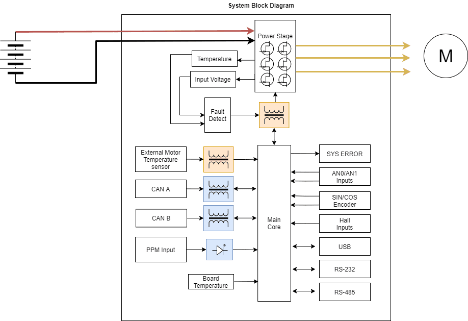
Peripheral used for motor control:
Opto Isolated PWM
CAN bus
Peripheral use for ESC telemetry:
Serial RS-232
Serial RS-485
USB
Any of the serial interfaces can be used to configure the internal variables of the MC110.
The ESC includes an internal SD memory which is used to record operating logs. The variables to store can be selected through the corresponding interface.
Note
The selected configuration interface cannot be used to send telemetry.
Mechanical Specifications
Protection: IP65 Aluminium
Weight: 2700 g
Maximum speed (1 pole): 300000 RPM
Dimensions: 27 x 26 x 8 cm
Electrical Specifications
Voltage: 100-550 V DC
Power: up to 55 kW
Note
Power depends on kind of motor, motor speed, battery voltage and current comsuption).
Please note that the maximum power is reached at maximum voltage (550 V), even at maximum switching frequency (16 kHz) and at 50 ºC ambient temperature.
Peak Current (<5 s): 400 A
PWM Frequency: 10-16 kHz
Input current (continuous): 200 A
Regenerative brake
Sensorless mode: MC110 is able to operate with sensorless motors with maximum efficiency.
Note
The sensorless mode does not require a minimum speed to measure it and operate, as long as MC110 provides current to the motor phases (since the speed is measured with the current)
Sensored motors:
Hall sensors
Digital incremental encoders
Analog SIN/COS
Reverse rotation: MC110 can operate in any direction of rotation without additional configuration.
Configurable:
Type of Observer
Programmable acceleration curve
Motor direction
Overvoltage threshold
Overcurrent threshold
Overtemperature threshold
Max. RPM (limit)
Braking force
Duty Cycle
Communications:
2x Isolated CAN Bus
3x PWM
Opto PWM
RS232
RS485
USB
Redundant control
Telemetry:
Motor & ESC temperature
RPM
Input voltage
Input/Output current
Data recording
VCC
This is the main power input for the secondary part of the driver. It must be powered with a voltage of 8 to 20 V.
The consumption of this pin also depends on the loads connected to 5 V pin.
Status |
Value |
|---|---|
Standby |
6.6 W |
Active |
13.2 W |
Note
No load on 5V output.
Interfaces
HALL Inputs
Warning
The employed hall sensors must not exceed 5 V.
These inputs are used to add to the system a feedback in sensored mode (incremental type, usually magnetic).
The 3 Hall efffect sensors must be placed at 120º (Electrical degrees) of each other. The following is a simple formula for obtaining the mechanical degrees of separation when installing the sensors:
So the sensors must be placed one of each other at:
For example, for 10 pole pairs:

Example diagram
Tip
The arc length between sensors can be calculated with the following equation:
FAN_PWM
This 0-3.3 V output is used to control an external fan if needed. External power for the fan is required, and it is important that the GND connection of this supply is the same as the GND connection for the supply of the control group (user connector).
Opto PWM Input
This input is an optocoupled control digital signal.
The input is interpreted as 0-100 % of the maximum RPM. An initial dead band can be configured to prevent the engine from starting.
Type |
Specification |
|---|---|
Input voltage range |
0-5 V |
Minimum input current |
2.5 mA |
Pulse length |
1-2 ms |
Frequency |
40-250 Hz |
NTC/PTC Input (External Temperature Sensing)
A PTC or NTC can be integrated.
Warning
The PTC or NTC must not exceed 5 V.
The PTC/NTC should be connected on the low side of an external resistor divider. This is the configuration by default. A high side connection can be used too, but a custom modification is needed.
The isolated Voltage_ref output should be left floating in default mode. The iso_ground is the return path of the NTC/PTC sensor.
ERROR SIGNAL
This signal indicates if there is an error within the MC110. A positive voltage of 3.3 V means that there is no problem.
SIN/COS_SIGNAL
These signals are those dedicated to the SIN / COS type analog sensor.
Warning
SIN/COS signals must not exceed 5 V.
USB
This is the interface normally used to configure the MC110 internal parameters.
The connection and disconnection of the USB related signals should always be done when the power supply (via the VCC input) is on.
Note
Not recommended for sending telemetry by default.
RS-232
Single ended serial type protocol:
Type |
Specification |
|---|---|
ESD Protection |
±15 kV (HBM) |
Requirements |
TIA/EIA-232-F and ITU v.28 |
Speed |
Max. 250 kbit/s |
Input Voltage |
-25 to 25 V |
Output Voltage |
-13.2 to 13.2 V |
RS-485
Differential serial type protocol:
Type |
Specification |
|---|---|
ESD Protection |
±15 kV (HBM) |
Requirements |
TIA/EIA-485-A |
Speed |
Max. 25 Mbit/s |
Input Voltage(D) |
-0.5 to 7 V |
Output Voltage (D) |
1.5 to 2.4 V |
CAN
Differential communication protocol:
Type |
Specification |
|---|---|
ESD Protection |
±4 kV (HBM) |
Requirements |
ISO11898-2 |
Speed |
Max. 5 Mbit/s |
Input Voltage(D) |
-12 to 12 V |
Output Voltage (D) |
2.9 to 4.5 V |
Mating connectors
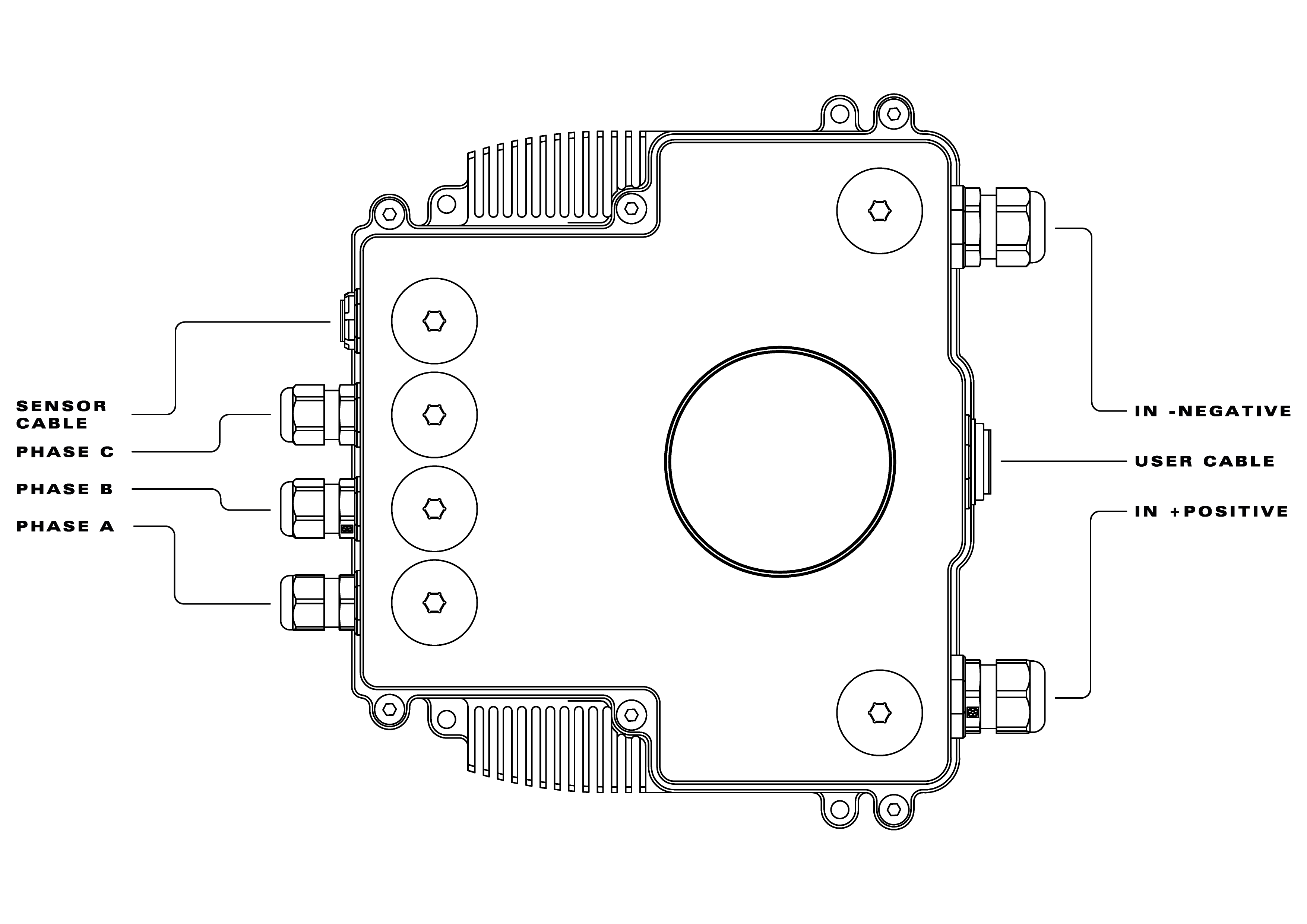
Separated connectors
Name |
Embention reference |
|---|---|
Sensor cable |
P001635 |
Phase C |
P005639 |
Phase B |
|
Phase A |
|
In negative |
P005640 |
In positive |
|
User cable |
P001634 |
Included connectors with MC110
Name |
Embention reference |
|---|---|
Veronte Harness of 24 pins for user connector |
P001634 |
Veronte Harness of 16 pins for sensor connector |
P001635 |