Hardware Installation
Note
When working voltage is higher than 60V, use of insulating gloves are mandatory for installation and the system must have a chassis fault detection system.
Warning
 Careful! The system slowly discharges the voltage on the input terminals when the battery is disconnected. Capacitors may remain charged unless enough time has passed.
The MC110 system has the following positions of mounting holes:
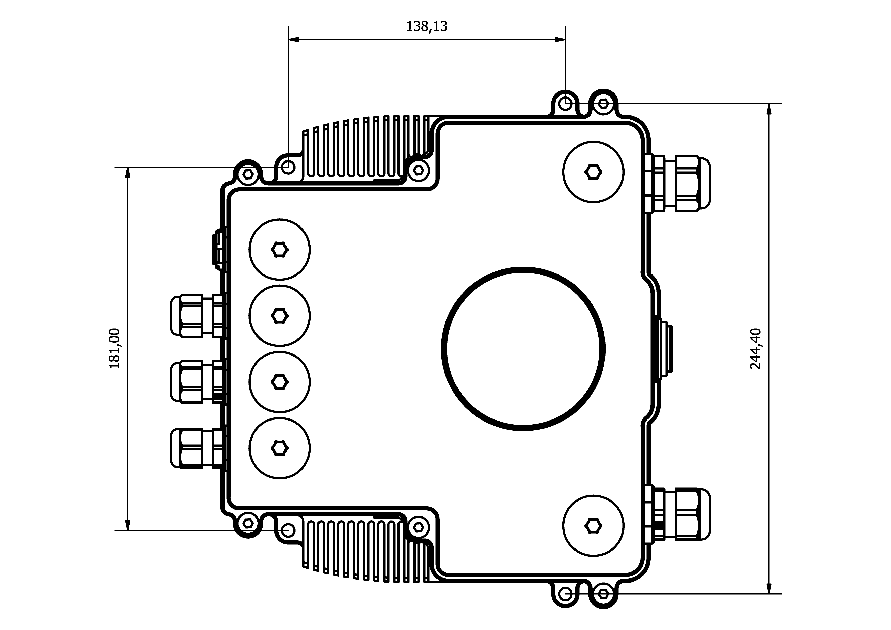
Mounting Holes
To dissipate the heat from the MC110 properly, there is a need to provide 16m/s of air speed against the heatsink.
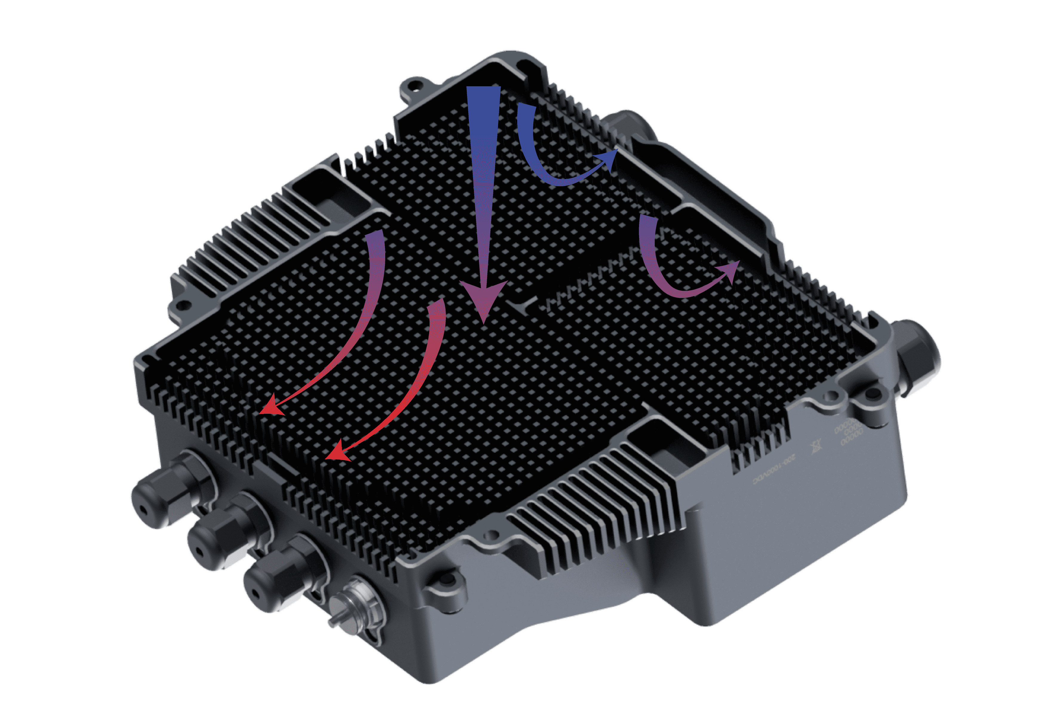
Airflow dissipation
ESC-Motor Wiring
Warning
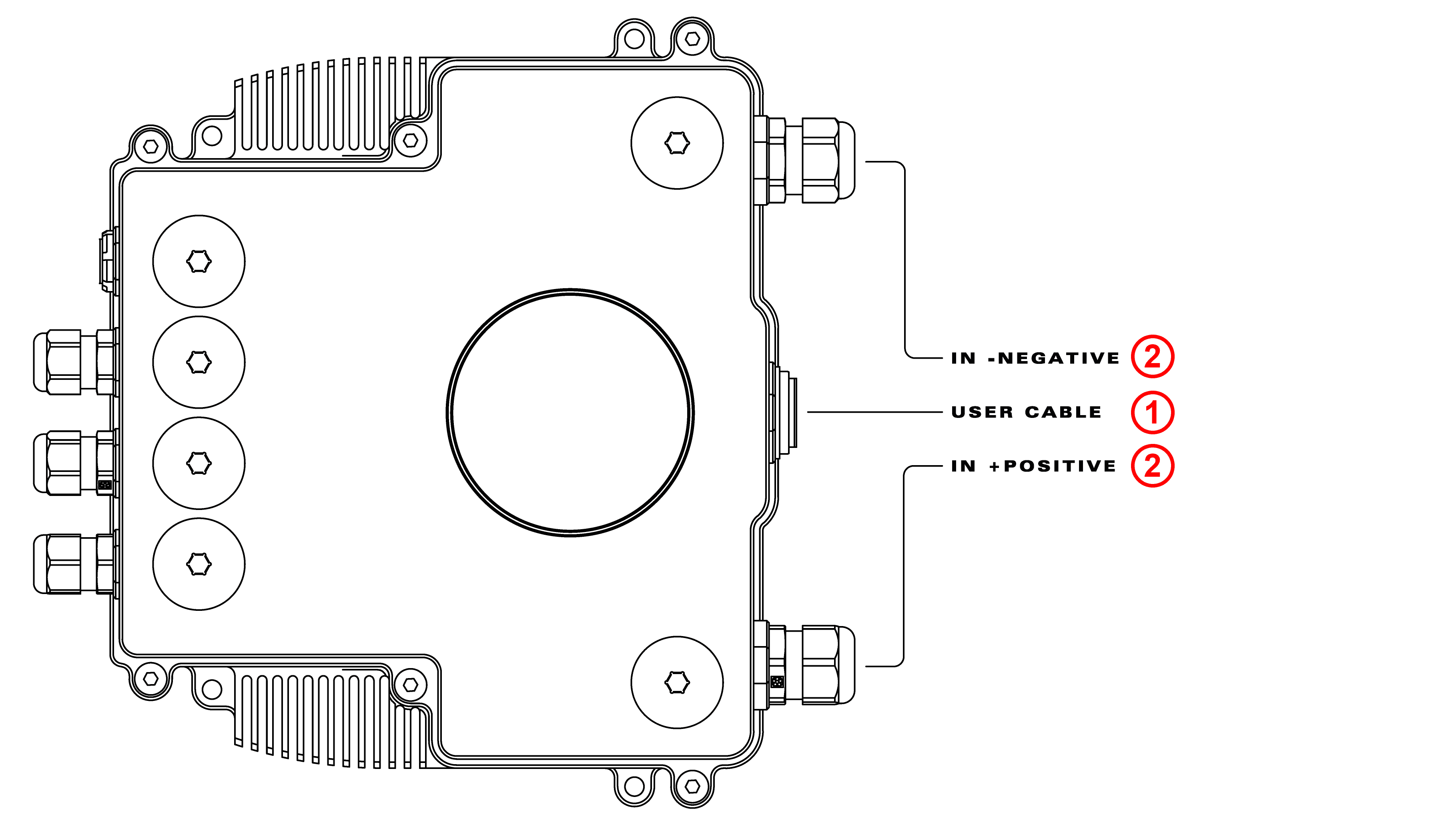
The polarity connection of the input must be respected, otherwise a short circuit may occur.
The polarity and connection is indicated in the following image.
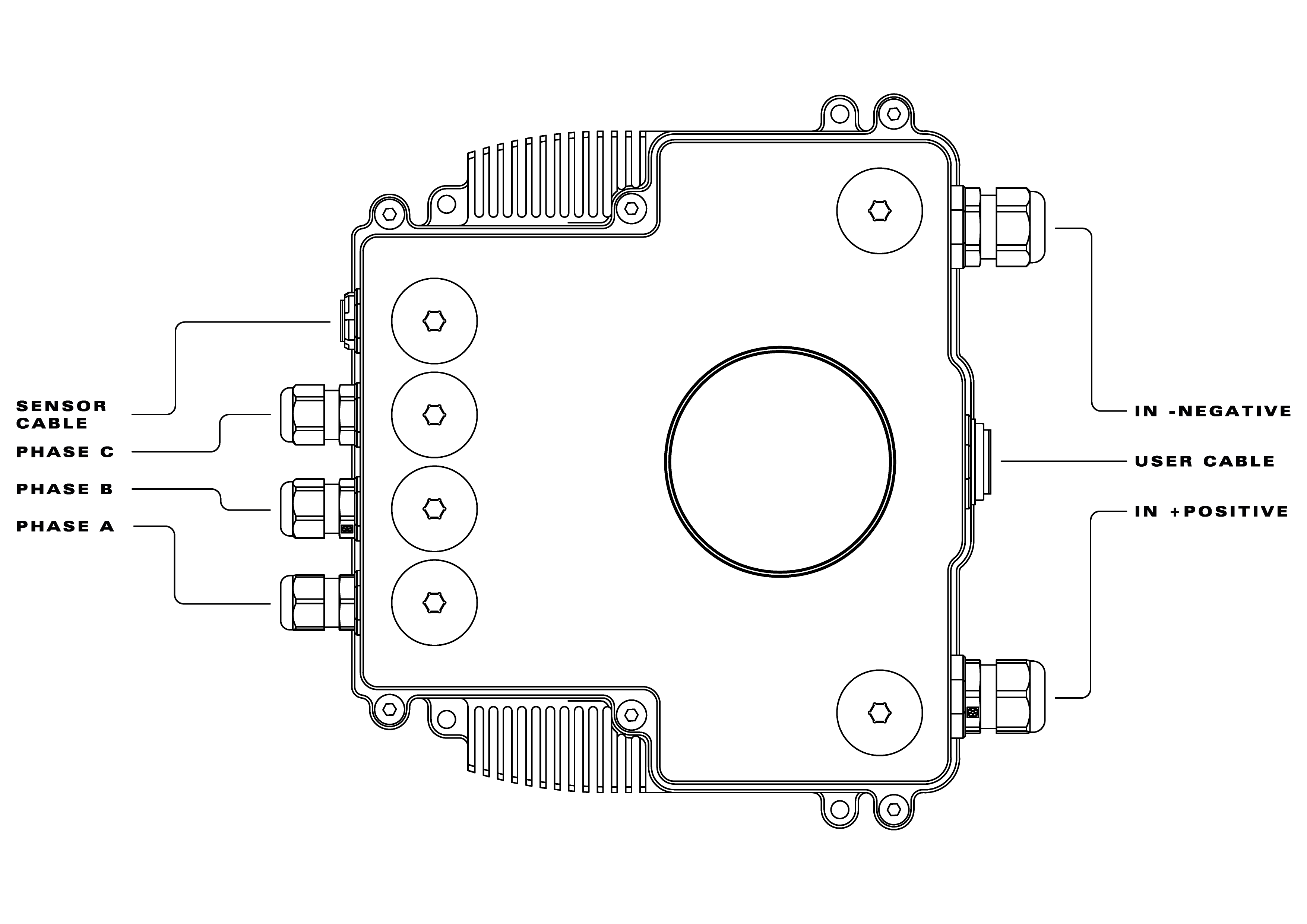
In order to access the connections remove the caps near each connector.

The section of the cables must be dimensioned according to input/output max power
Connection of the phases can be done freely, however, it will affect the direction of rotation of the motor. Hence, if the motor is spinning in the opposite direction, switch any 2 phases around.
Pinout
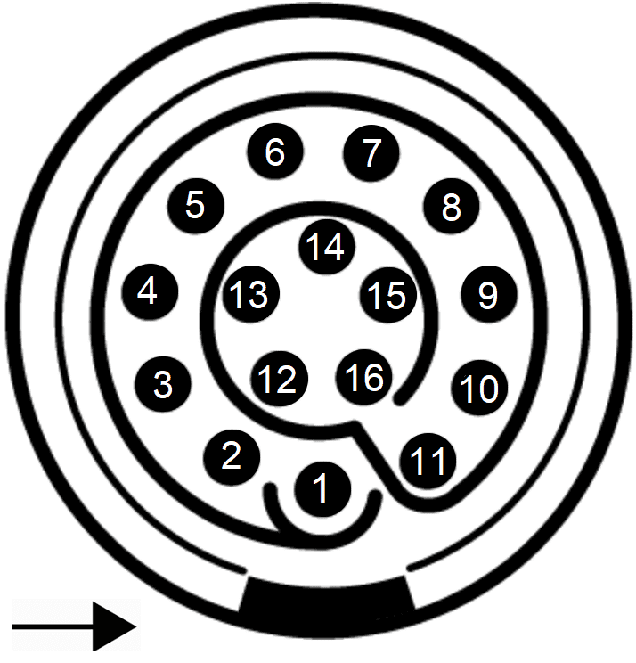
The user connector pinout is shown in the following figures and table:
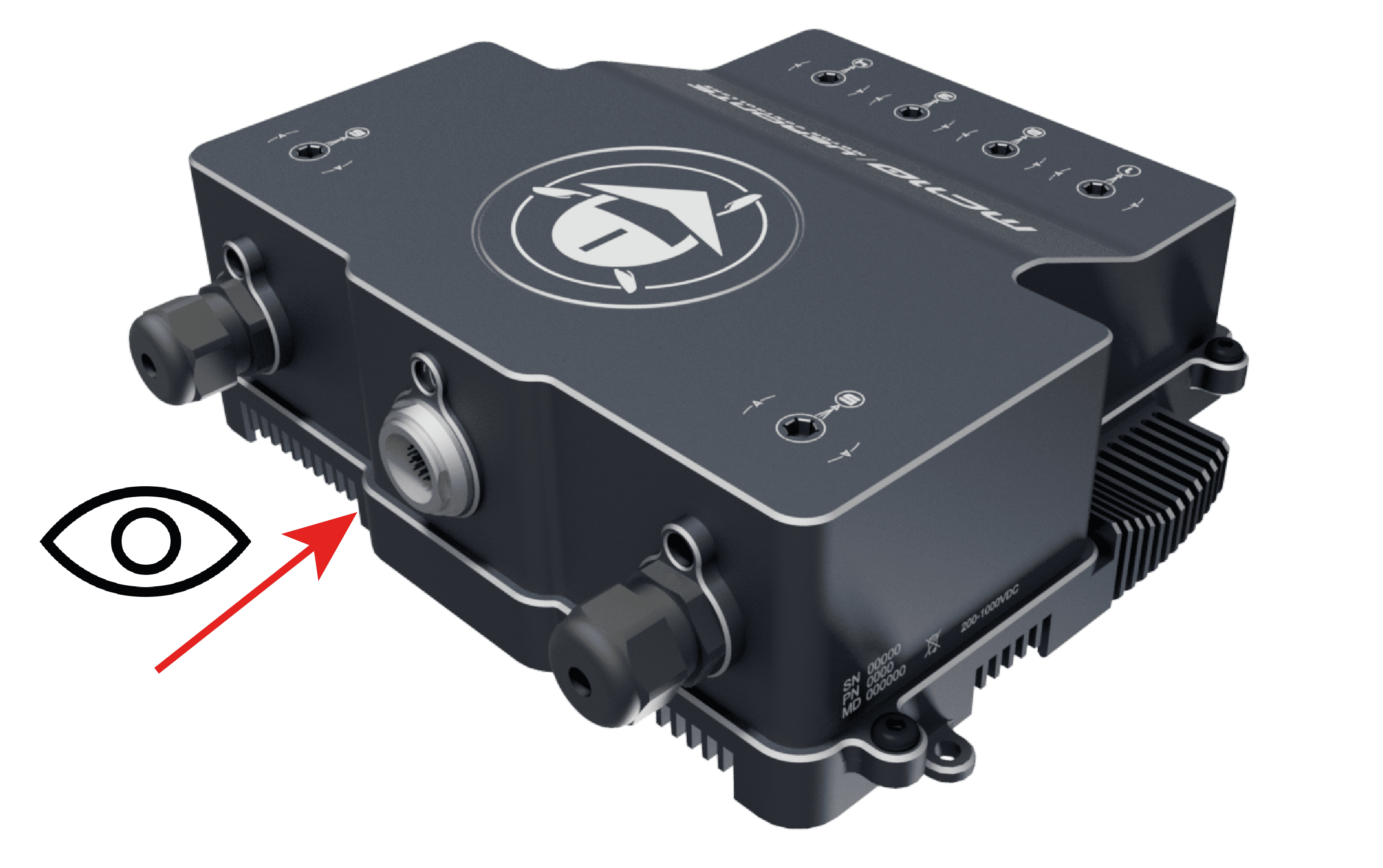
Point of view
User connector |
Connector EEG.3k.324.CLN |
Matching connector |
Connector FGG.3K.324.CLAC90 |
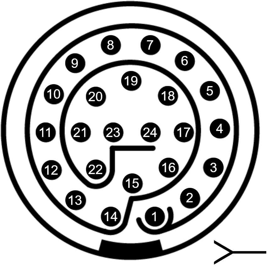
User connector (frontal view)
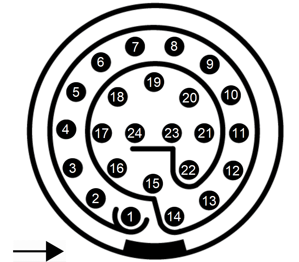
Matching connector (frontal view)
Pin |
Signal |
Type |
Comment |
|---|---|---|---|
1 |
ERROR_SIGNAL |
Digital Status Signal |
High: OK, Low: NO OK |
2 |
OPTO_PWM |
Optocoupled Digital Input |
|
3 |
VCC |
Digital Supply |
8-20V |
4 |
GND |
Digital Ground |
|
5 |
CANA_P |
CAN Communications |
|
6 |
CANA_N |
CAN Communications |
|
7 |
CANB_N |
CAN Communications |
|
8 |
GND |
Digital Ground |
|
9 |
RS485_OUT_P |
RS-485 Communication |
|
10 |
RS485_OUT_N |
RS-485 Communication |
|
11 |
FAN_PWM |
Digital Output |
|
12 |
GND |
Digital Ground |
|
13 |
RS485_IN_P |
RS-485 Communication |
|
14 |
RS485_IN_N |
RS-485 Communication |
|
15 |
RS485_GND |
RS-485 Communication |
|
16 |
OPTO_RETURN |
Optocoupled Return |
|
17 |
GND |
Digital Ground |
|
18 |
CANB_P |
CAN Communications |
|
19 |
USB_N |
USB Communication |
|
20 |
RS232_RX |
RS-232 Communication |
|
21 |
GND |
Digital Ground |
|
22 |
RS232_TX |
RS-232 Communication |
|
23 |
USB_P |
USB Communication |
|
24 |
CAN_GND |
CAN Ground |
The sensors connector pinout is shown in the following figures and table:
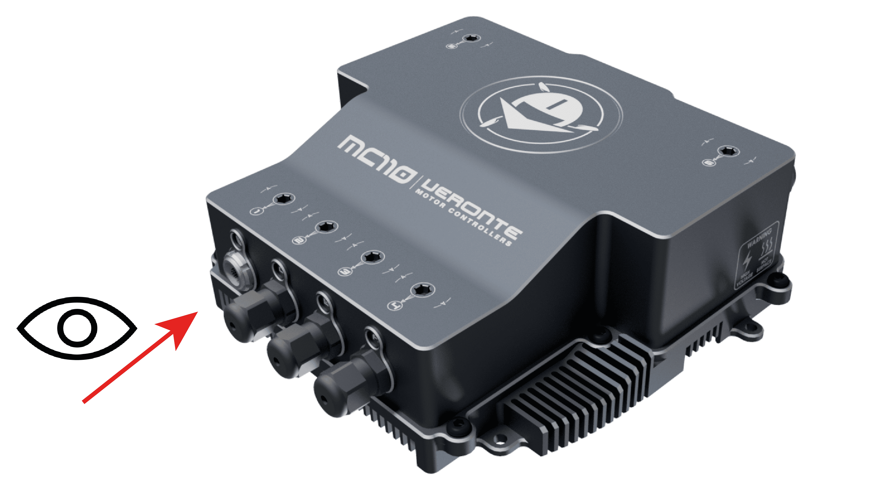
Point of view
Sensor connector |
Connector EEG.1K.316.CLN |
Matching connector |
Connector FGG.1K.316.CLAC65Z |
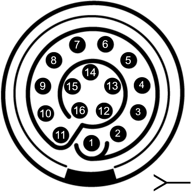
Sensor connector (frontal view)
Matching connector (frontal view)
Pin |
Signal |
Type |
Comment |
|---|---|---|---|
1 |
HALL_1 |
Hall Sensor 1 Input |
|
2 |
NC |
No Connect |
|
3 |
NC |
No Connect |
|
4 |
NC |
No Connect |
|
5 |
COS_SIGNAL |
Cosine Input |
SIN/COS Encoder |
6 |
SIN_SIGNAL |
Sine Input |
SIN/COS Encoder |
7 |
ISO_GND |
Isolated Ground |
|
8 |
NTC/PTC |
NTC/PTC Input |
|
9 |
ISO_GND |
Isolated Ground |
|
10 |
HALL_3 |
Hall Sensor 3 Input |
|
11 |
HALL_2 |
Hall Sensor 2 Input |
|
12 |
ISO_GND |
Isolated Ground |
|
13 |
ISO_GND |
Isolated Ground |
|
14 |
5V |
Isolated 5V |
|
15 |
VOLTAGE_REF |
Voltage Reference Output |
Use for NTC |
16 |
ISO_GND |
Isolated Ground |
How to Turn On and Off
MC110 has two electric circuits: control and power. To turn on the voltage supply (with devices such as switches, relays or MOSFETs), it is mandatory to do it with the following order: first of all the control group, and then the power group.
The control group is in the user cable. The power circuit is in the negative and positive cables. Then the enabling order is summarized in the following figure:
Turn on order
To turn off the MC110, the disabling order is reversed: first power circuit (input negative and positive), then the control circuit (user cable).
How to connect MC110 for CAN communication
Connect three cables to CAN A positive, CAN A negative and GND from the user cable. These pins are indicated in the Pinout section. There is not any resistor termination, so the connection is direct.