Quick Start
First steps
To connect the MC110 to a PC, use the USB_N, USB_P AND A GND. These pins for MC110 are explained in the Pinout section.
The USB pins are summarized as follows:
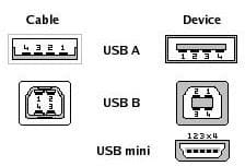
USB pins
Number |
Name |
Cable color |
Pin |
|---|---|---|---|
1 |
VCC |
Red |
+5 VDC |
2 |
D- |
White |
Data - |
3 |
D+ |
Green |
Data + |
4 |
GND |
Black |
Ground |
Warnings
When installing the MC110 speed controller in the vehicle, the following limitations shall be considered:
The distance between the battery, the controller system and the motor should be as short as possible in order to maximize the efficiency. It is preferable to place the controller system as close to the battery as possible and extend the cables from the controller to the motor. Calibration will be needed depending on the final setup.
The wire connections type between the power items must be crimped not soldered.
The system must be placed in a ventilated place with proper air flow. If this is not possible, it is necessary to install an external fan.
The vehicle must have an inrush current limiter when powering MC110 for the first time.
PID tuning is strongly not recommended, since it nullifies the warranty.
An unappropriated use of the MC110 exempts Embention from responsabilities related to any damage.
Embention shall have no responsibility, obligation or liability in any manner for and in respect of any inappropriate use by the client, such as (including but not limited to) not implementing sufficient cooling airflow, applying according to the indications given by Embention.
Requirements
Cooling airflow: a fan or any other ventilation method is required to refrigerate the MC110.
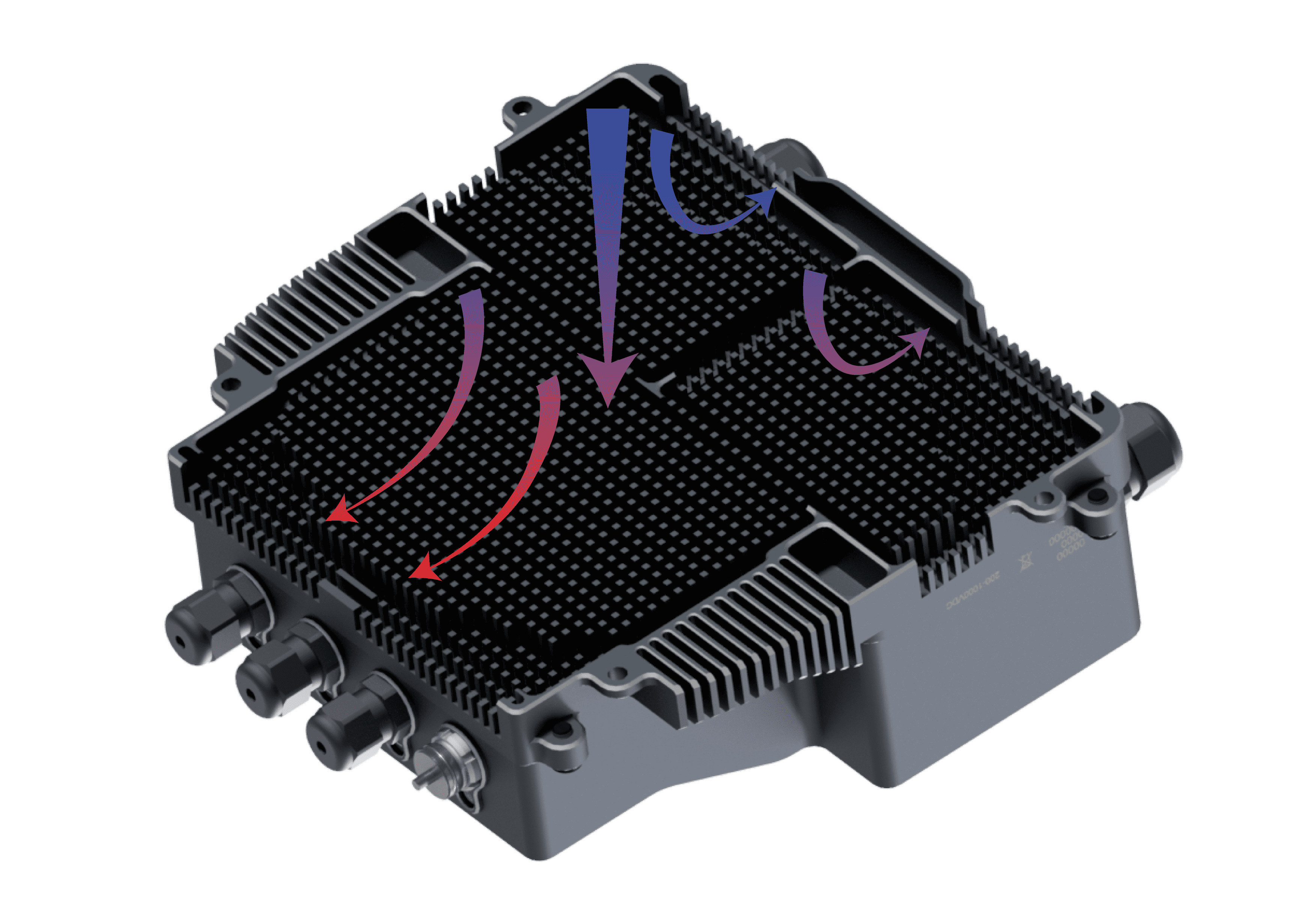
Airflow dissipation