Integration examples
Serial connection
As the com port configuration is common to all devices, the following steps are applied to MC24 and MC110 controllers as an example.
Once Veronte Link is installed, the first step that must be done is to set the connection that your MC unit is currently using. By default, every MC is capable to comunicate through USB, RS232 and RS485 so any of these can be used (properly adapted to USB/serial).
First, click on “+”:
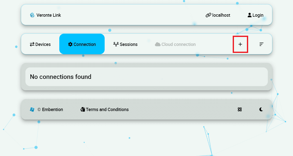
Add new connection
Besides, it is required to find out which port is employing the MC unit. Windows allows to do that with the Device Manager from the Control Panel.
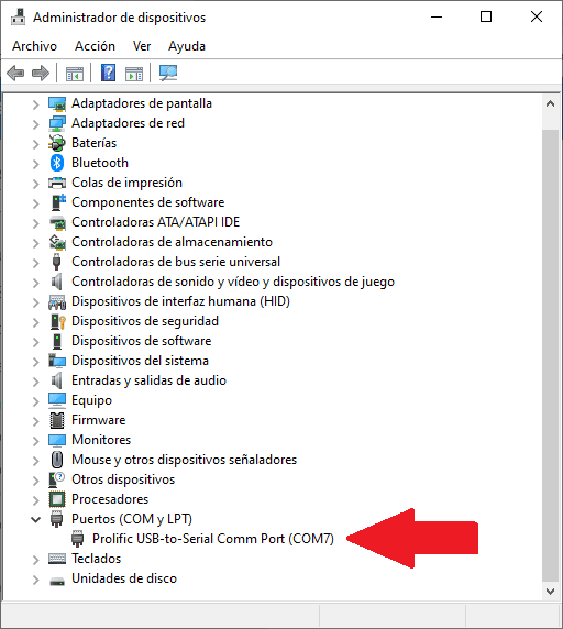
Windows Device Manager
Select your COM settings by entering the Comm Port previously found. Normally, the other default parameters should not be changed.
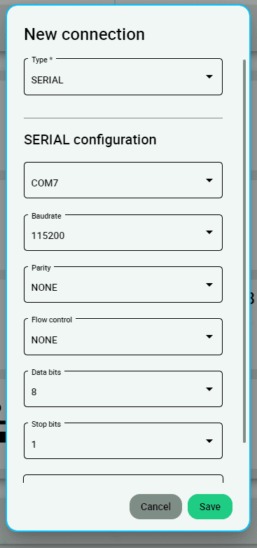
New connection configuration
If the selected port is correct and everything went well, a new MC will be displayed in the devices list. However, the device status will remain as CFG: Waiting to read.
The user is ready now to start configuring the motor controller using MC PDI Builder.
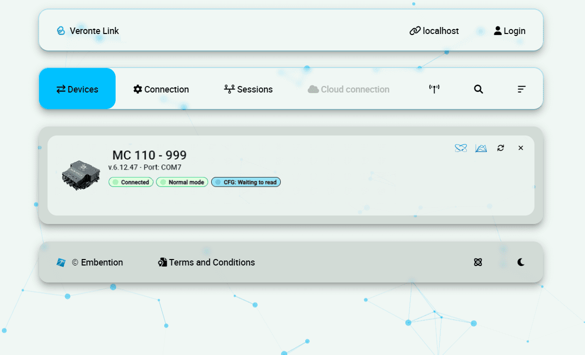
MC unit correctly connected
More Veronte devices (MC units, Veronte Autopilots, etc.) could be added following these instructions.
Note
In case of connecting a Veronte Autopilot 1x, after a few seconds, the device status should replace CFG: Waiting to read by CFG: Ready, since only Autopilot 1x is able to change or load configuration in normal mode.
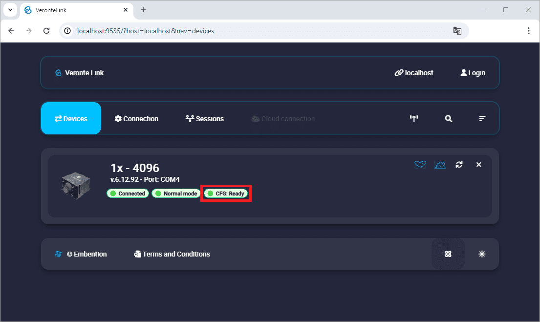
Veronte Autopilot 1x connected and ready
For other Veronte devices than 1x, CFG: Not Downloaded is equivalent to CFG: Waiting to read. Hence, CFG: Ready should replace the status CFG: Not Downloaded.
UDP connection
Wi-Fi/Ethernet configuration
The following steps are applied to a PCS unit as an example.
Important
If connecting through Ethernet, step 1 does not apply.
The first step is to look under available networks for the PCS unit and connect to it.
Once the connection is made, enter Veronte Link and configure the UDP connection in the Connection menu.
First, click on “+”:
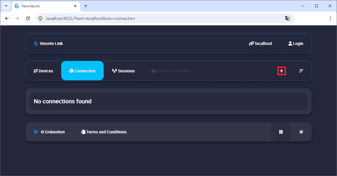
Add new connection
Then, the configurable parameters must be entered.
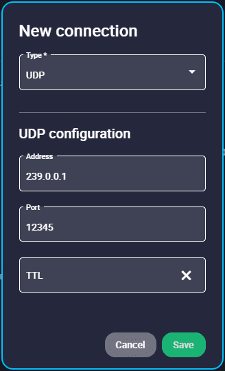
New UDP connection configuration
Important
This address and port are configured for this PCS unit, they do not have to be the same for another device.
Finally, if the configured connection is correct and everything went well, a new PCS will appear in the device list and the device status will change to CFG: Ready.
The user is ready now to start configuring the PCS using 1x PDI Builder.
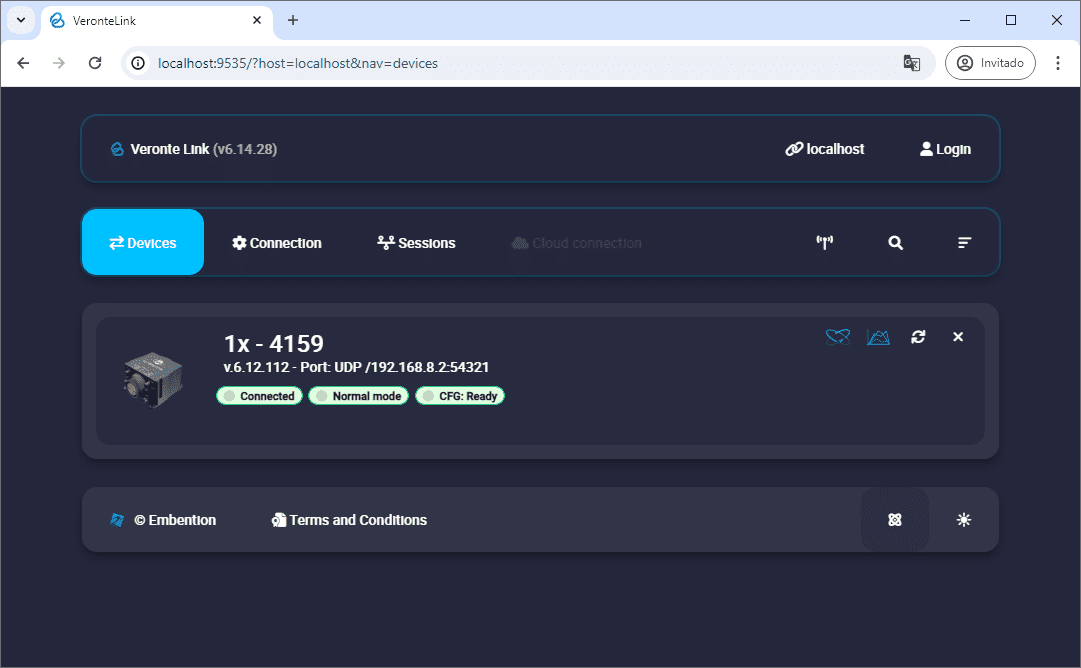
PCS unit correctly connected
Note
The image of a Veronte Autopilot 1x is displayed and not a PCS as the device that is actually connected is the Autopilot 1x inside the PCS.
TCP-SERVER connection
Ethernet configuration
The following steps detail how to connect Veronte Link to an Autopilot 1x via a TCP connection to a Microhard radio.
Note
In this connection, the radio acts as “Client” and Veronte Link as “Server”.
Configure, in the Microhard WebUI, the radio as “TCP Client” and enter the following parameters:
Remote Server IP Address: IP address of the PC.
Remote Server port: TCP port to which the radio has to connect. It must be the same as the one configured in Veronte Link.
For more information on the radio configuration, users can refer to the Microhard radio configuration - Integration examples section of the 1x Hardware Manual or directly to the Microhard radio documentation.
Connect Veronte Autopilot 1x to the Microhard radio via RS232 as detailed in the Microhard pDDL900-ENC external - Integration examples section of the 1x Hardware Manual.
Once the configuration and connection is done, open Veronte Link and configure the TCP-SERVER connection in the Connection menu.
First, click on “+”:
Add new connection
Then, the configurable parameters must be entered.
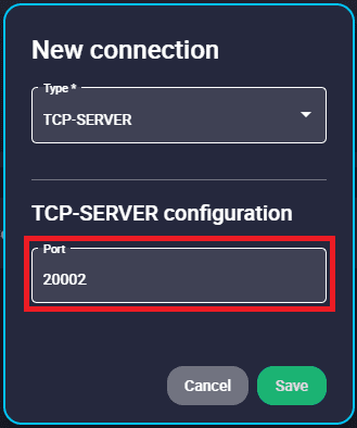
New TCP-SERVER connection configuration
Port: Enter a TCP port to which the radio will be connected, the same as the one previously configured as “Remote Server port” in the radio configuration.
Finally, if the configured connection is correct and everything went well, a new Autopilot 1x will appear in the Devices list. It should look like this:
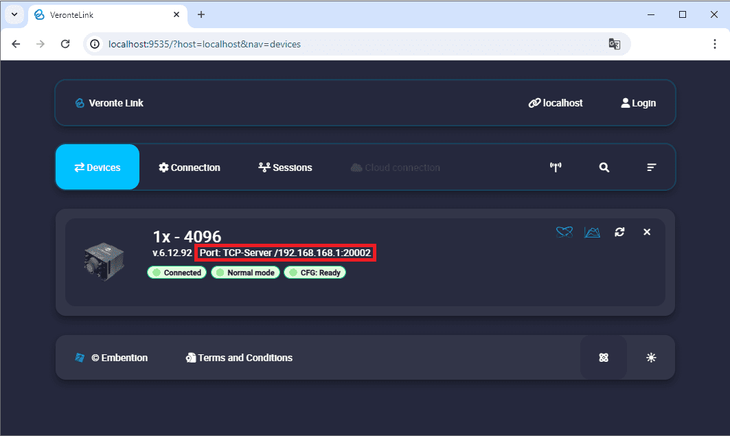
1x unit correctly connected
TCP-CLIENT connection
Ethernet configuration
The following steps detail how to connect Veronte Link to an Autopilot 1x via a TCP connection to a Microhard radio.
Note
In this connection, the radio acts as “Server” and Veronte Link as “Client”.
Configure, in the Microhard WebUI, the radio as “TCP Server” and enter a “Local Listening Port” to which Veronte Link will have to connect (usually the default one is used).
For more information on the radio configuration, users can refer to the Microhard radio configuration - Integration examples section of the 1x Hardware Manual or directly to the Microhard radio documentation.
Connect Veronte Autopilot 1x to the Microhard radio via RS232 as detailed in the Microhard pDDL900-ENC external - Integration examples section of the 1x Hardware Manual.
Once the configuration and connection is done, open Veronte Link and configure the TCP-CLIENT connection in the Connection menu.
First, click on “+”:
Add new connection
Then, the configurable parameters must be entered.
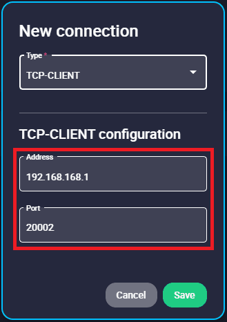
New TCP-CLIENT connection configuration
Address: IP address of the radio.
Port: Enter as TCP port the “Local Listening Port” previously set in the radio configuration.
Important
This address and port are configured for this radio unit, they do not have to be the same for another device.
Finally, if the configured connection is correct and everything went well, a new Autopilot 1x will appear in the Devices list. It should look something like this:
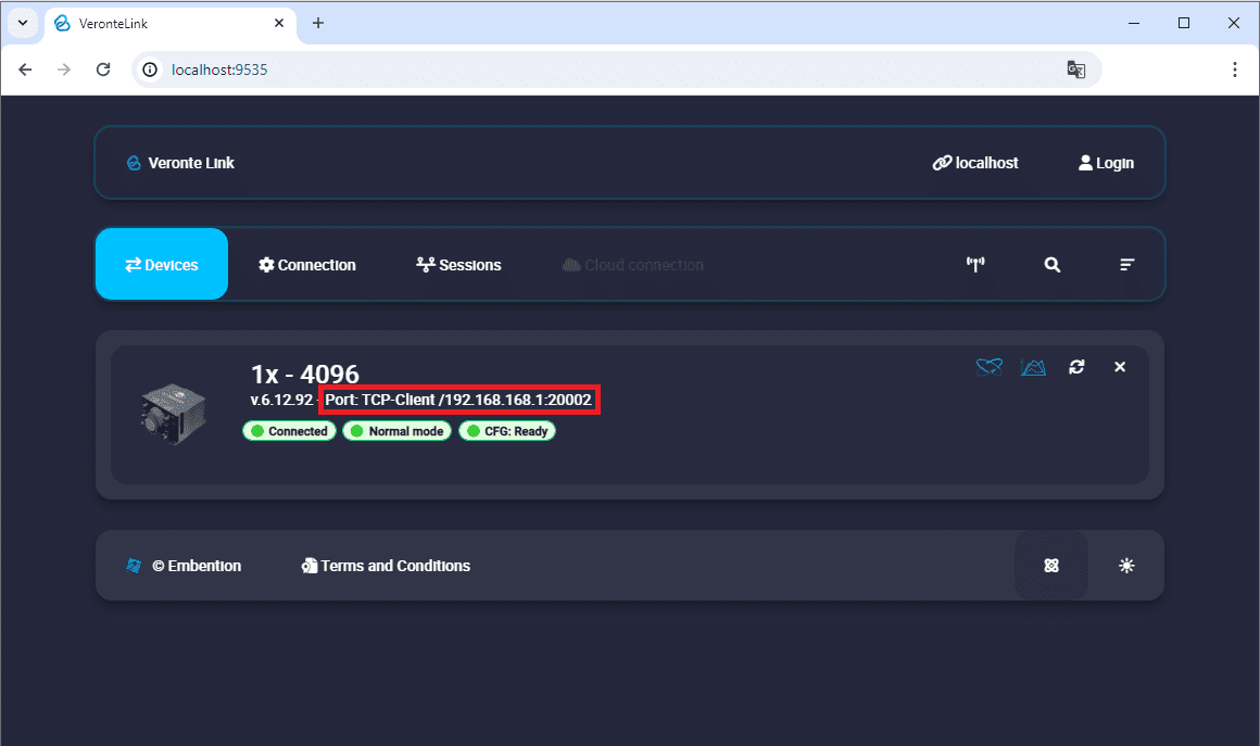
1x unit correctly connected