Veronte Ground Configuration
The first step of the configuration is the creation of the SU matrix including 2 controls (PAN-TILT) and 2 servos, the ones installed on Veronte Tracker in order to move Pan and Tilt axes.
SU Matrix
Once the SU matrix is complete, it is possible trimming both servos with the same procedure of aircraft servos in the Devices > Actuators panel. The user must set the center of the antenna and then maximum and minimum angles. The procedure has to been repeated for both servos.
Servos Trimming
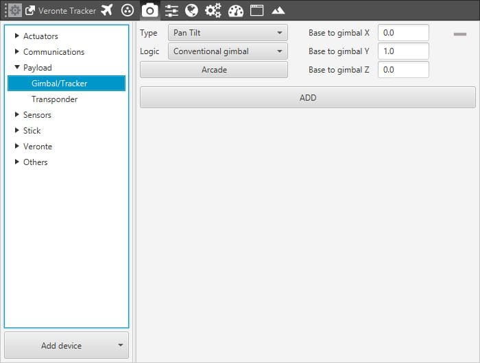
When servos are trimmed, the tracker has to be configured in the Devices >Payload panel as:
Type: Pan Tilt.
Logic: Conventional Gimbal, with Horizontal (Pan) and vertical (Tilt) axes.

Tracker Payload configuration
Next step is the configuration of the control loops for each axe: Pan and Tilt.
Pan control loop is a closed loop with Joint 1 of gimbal 1 entry variable (the desired Pan angle) and the Encoder Angle variable in the feedback loop. The output is configured as the SU matrix: Control Output u1.
Pan Loop Configuration
A typical setting for the loop is presented in the following figure. The proportional gain is set at 0.2 and the integral gain at 3.0.
Pan Control Loop
For the Tilt control, an open control loop is sufficient. Joint 2 of gimbal 1 is the entry variable (the desired Tilt angle) and the Zero variable is configured for the feedback loop. For those cases where an encoder is present it should replace Zero as feedback for Tilt angle. The output is configured as the SU matrix: Control Output u2.
Tilt Loop Configuration
Tilt Control Loop
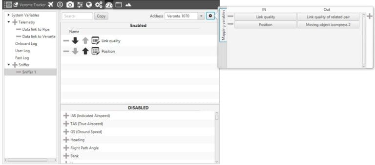
The last step of the Veronte Ground configuration is the Sniffer setting. Configuring a new Sniffer means allowing the Ground Station “knowing” the Veronte Air (UAV Address) position during flight and associating it with a Moving object. Veronte Air has to be configured to send its position to Veronte Ground. On Address it has to be selected the Veronte Air to be tracked.

Sniffer Ground Configuration
