Stick
The following content will help the user to configure the stick parameters for manual and arcade modes – more information about these modes in Modes.
The movement that the pilot makes on the stick produces variations on a vector called \(R\) of length \(n\), where \(n\) goes from 1 to the total number of employed transmitter channels. The values reached by the components of \(R\) are limited between 0 and 1. These stick movements need to be processed to produce the input signals that will go into the control algorithm, in the case of arcade mode; or directly into the servos for manual mode.
The process begins by mapping each one of the sticks inputs to PWM signals into a vector called \(Y\) of length \(m\), where \(m\) goes from 1 to the total number of actuators. The full definition of \(Y\) is \(Y=YR \cdot R+Y_{0}\), where :
\(\boldsymbol{YR}\) is a matrix that transforms raw stick inputs \(R\) to PWM sigals \(Y\).
\(\boldsymbol{Y_{0}}\) is an offset vector, which corrects the \(Y\) vector.
The above parameters are defined at beginning of the Stick menu (as seen in the Figure below). There is a Wizard Stick button that sets \(YR\) and \(Y_{0}\), which has a dedicated section below.
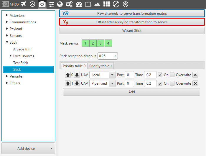
Stick - Configuration Parameters
Let’s consider a quadocopter. With such platform applying thrust produces an increase in the rotation speed of the four engines, and only one stick channel (throttle) is required to achieve that. So here the mapping will be that an increase in one component of \(R\) has to produce an increase in four components of \(Y\). Doing the same with the rest of stick channels (pitch, yaw, roll) will generate matrix \(YR\):
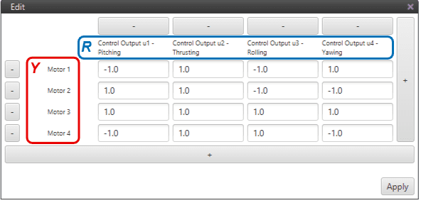
Stick - \(\boldsymbol{YR}\) Matrix for a Quadcopter
Keep in mind that each stick channel (throttle, roll, yaw, pitch, etc) depends on the mode of the transmitter, i.e. the sticks’ physical layout. There are 4 different modes and there is no prevailing type, it really depends on the pilot. In the following Figure a Mode 2 channel layout is depicted:
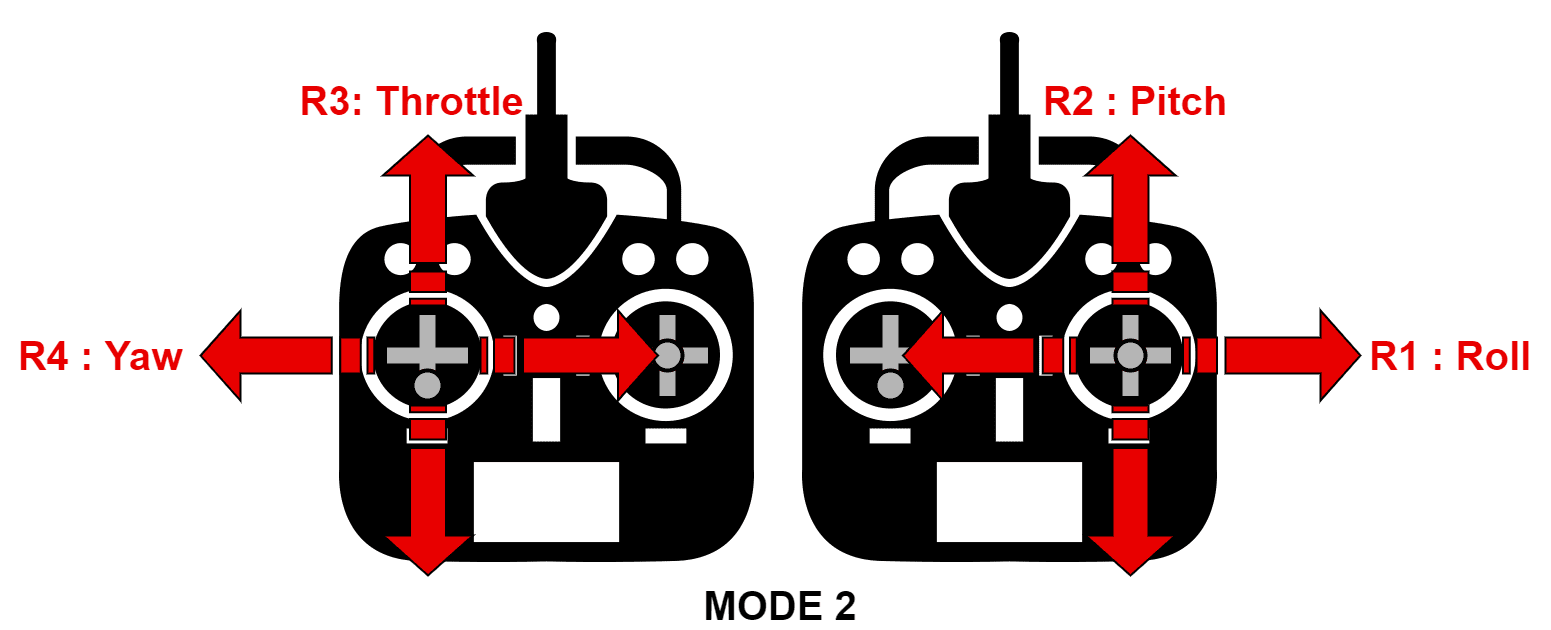
Stick - Channels Layout
The offset \(Y_{0}\) is calculated by setting \(R\) and \(Y\) with a specific value. Take the neutral position of a quadcopter: the sticks are \(R_{neut}=[0.5 ;\, 0.5 ;\, 0 ;\, 0.5]\) (the third value is 0 as it corresponds to the neutral position of channel 3, i.e. the throttle) and the actuators PWM signals \(Y_{neut}=[0 ;\, 0 ;\, 0 ;\, 0]\). Then, the solution for the offset vector will be: \(Y_{0}=Y_{neut}-YR \cdot R_{neut}\). The neutral position information will be asked when using the Wizard Stick button.
Stick - Transformation Diagram
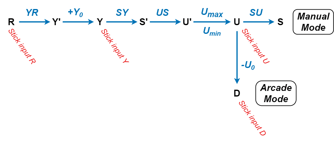
The above diagram depicts the whole transformation process of the incoming raw input \(R\) vector. It also shows in red the naming of some important variables in Veronte Pipe. Step by step, the process is:
From \(R\) one gets \(Y'\) using \(YR\), as defined above.
From \(Y'\) one gets \(Y\) adding \(Y_{0}\).
From \(Y\), using the trim of the servos, one gets the actuator output \(S'\). PWM to actuator output mapping \(SY\) is defined in Devices - Actuators - Physical. The mapping consists in a piecewise-linear function relating each actuator output \(S\) to a certain amount of PWM signal \(S\):
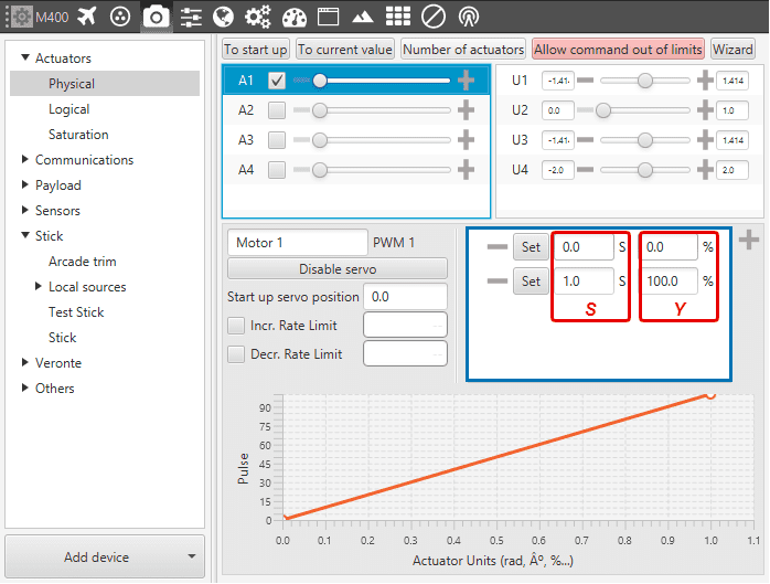
Linear Mapping \(\boldsymbol{SY}\) of a quadcopter engine
From \(S'\), using the logical transformation matrix \(US\) (defined in Devices -> Actuators -> Logical), one gets \(U'\).
From \(U'\), and delimiting its values if they are higher or lower than the limit values \(U_{max}\) and \(U_{min}\), one gets \(U\). The limit values of \(U\) are found in Devices - Actuators - Physical.
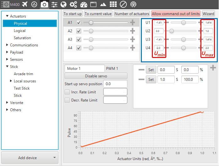
Limit values of \(U\)
From \(U\), substracting the arcade trim of the transmitter \(U_{0}\) one gets vector \(D\), which goes into the guidance control of the modes where arcade mode is enabled. More information on the arcade trim on Devices - Stick - Arcatedtrim.
Lastly, if manual mode is selected, one last transformation is required. From \(U\), applying \(SU\), one gets the final \(S\): actuator outputs.
Wizard Stick
To make use of this assitant tool, logical matrices \(US\) and \(SU\) must have been defined, otherwise it will not work.
When clicking on the button (see Figure below), the user is asked to associate each control output \(U\) of the platform with a stick channel \(R\). Doing so, matrix \(YR\) is automatically calculated.

Stick - Wizard Stick Configuration Parameters
In addition, to obtain \(Y_{0}\) the user needs to click on Configure Neutrals – otherwise it is considered as \(Y_{0}= {0}\). There, the neutral values of the actuator outputs \(S_{neut}\) (i.e. servo positions, engine rpms, etc) and the neutral values of the stick \(R_{neut}\) can be introduced manually. If Default Values button is clicked, \(S_{neut}\) is taken from Devices - Actuators - Physical, where its start-up position is defined.
If Get of Telemetry is clicked, \(R_{neut}\) is taken from the connected transmitter. The user should move the sticks to their netural position and then click on the button. Finally, to exit the assistant tool click on Accept.
Note
The assistant tool might not work for some configurations, such as hybrid platforms.
For those platforms where a same channel is used both for the plane and the quadcopter configuration, the stick configuration has to be done manually.
Mask Servos
This option is used to select which servos will “listen” to the commands sent by the stick. If the servo is selected (green box), it means the servo will be moved upon stick command. On the other side, if a servo is not selected (grey box), it will ignore the commands sent from the stick.
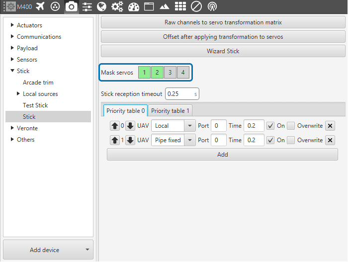
Stick - Mask Servos
Transmitter Inputs
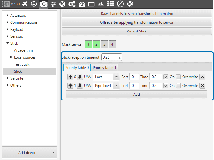
Stick - Transmitter Inputs
It is possible to set multiple transmitter inputs with the respective priority, from top to bottom.
UAV: defines the source of where the stick information is taken from. Local represents the actual selected autopilot (i.e. the transmitter is connected to it); Pipe fixed means the information is coming from the virtual stick; Broadcast means the information comes from all linked autopilots; and one particular autopilot, which needs to be visible in Pipe.
Port: from each source it is posible to have more than one stick information, e.g. two transmitters can be connected to the same autopilot. The port is an identifier to distinguish them.
Time: defines the time to consider the source inactive. Therefore the incoming stick information will be always the one from the source with higher priority and active. Once it is considered inactive the following active source will send its stick information.
ON: enables the source.
Overwrite: if marked, the stick information will be overwritten by this source when it becomes the active source.
