Setup
Introduction
A Mission can be configured making use of the Mission Menu. Missions can be created and managed though the Mission menu. First, make sure the autopilot unit where the mission has to be upload is selected, i.e. the Air unit. Right after, the aircraft trajectory can be drawn using the graphical tool of this menu, along with other auxiliary elements such as polygons, event markers or obstacles markings.
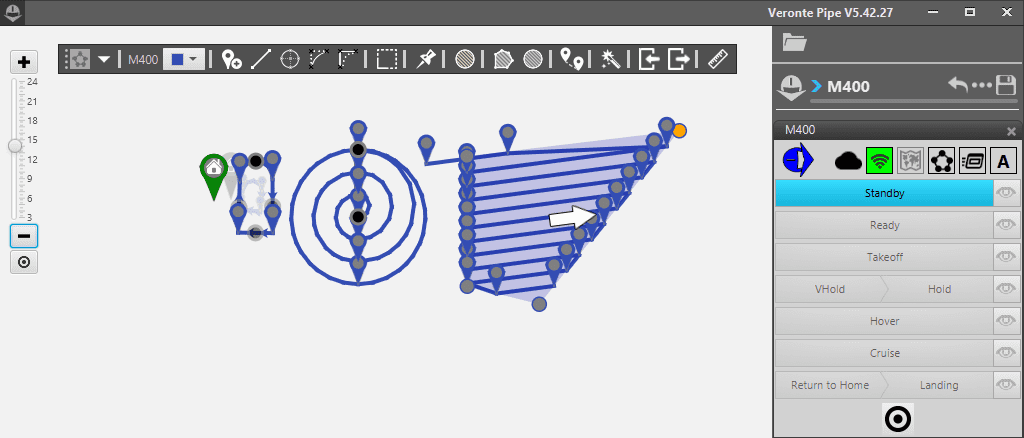
Mission Setup Examples
The user can manage two or more missions simultaneously open in Pipe, but be careful not to mix configurations. The paths created will be directly linked to the Cruise guidance mode, so each time the aircraft is in a phase with cruise guidance, it will start to follow the track created with the mission menu.
Terrain profile and magnetic field
Before starting the configuration of a new mission, the terrain profile and the magnetic field, Magfield, have to be set. Click on Open details button, ![]() , to access the settings.
, to access the settings.
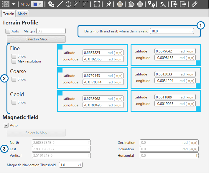
Terrain profile and magnetic field settings
Delta parameter: The distance to the ground (AGL) may be measured through two or more systems. Usually, an altimeter like a LIDAR in conjunction with the GPS signal and the meshes information are used. During flight, it is possible that the GPS position error is large enough that the height provided by the meshes does not correspond with the actual position. In order to avoid problems, the Delta parameter can be defined. This parameter defines a circumference radius where both systems will be used. If the estimated position error is bigger than the delta parameter, only LIDAR data will be used.
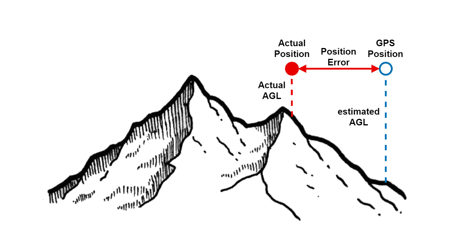
Delta Parameter
Meshes of terrestrial mode: three different are established: Fine, Coarse and Geoid.
Fine: Is the smaller mesh. Contains detailed information about terrain altitude.
Coarse: Medium mesh with not so much detail.
Geoid: World mesh which provides the geoid altitude.
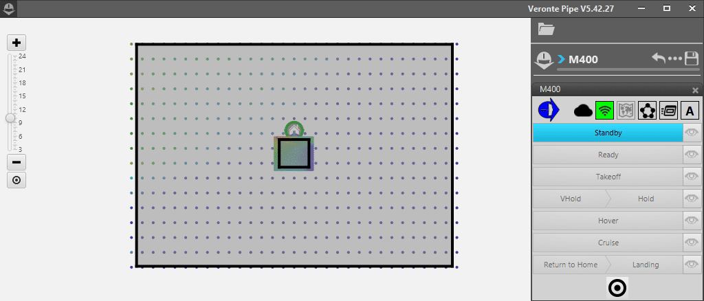
Fine and Coarse meshes setup
If “Auto” is enabled, the system will automatically place and adjust the meshes to optimal start dimensions. The user can modify them manually, also. First, deselect the “Auto” option. The coordinates of each upper left corner and lower right corner of the meshes’ rectangle can be introduced. Also, they can be set by hand by clicking and dragging the meshes and its edges around the map. In order to do that, click on “Show” to display the meshes on the screen.
In general, increasing meshes size will mean lower area definition. And greater resolutions smaller meshes, because it implies heavier data files.
“Margin” is the percentage at which the system will recalculate the mission if the route is displaced. In other words, if the mission is displaced 60% out of the area (Coarse or Fine) and the margin is set to 80%, the mission will be not recalculated. If the mission is 81% (or more) away from the previous one, the system will recalculate the mission. A low level (or zero) margin means more terrain profile precision but the system will have to recalculate the meshes more times (or each time) when the mission is modified.
Magnetic vector: the magnetic vector of the mission’s area should be introduced. As far as the Magfield is concerned, it is recommended to select the “Auto” option to take the magnetic declination information of the mission area.
Warning
Check that meshes position are over the mission area before flying, especially if carrying out an operation in mountainous terrain.
Marks
Marks are an important feature to Pipe and the missions. Marks can trigger actions when the aircraft passes through them. Actions can be configured in the Automations Menu.
There are two possible options to add a new mark. One is through the “Event Mark” button on the Mission toolbar ![]() , which allows the user to create a new mark on a route track directly or attached to an individual waypoint, or via the Marks flange on the Open Details
, which allows the user to create a new mark on a route track directly or attached to an individual waypoint, or via the Marks flange on the Open Details ![]() by clicking on “+” at the upper right corner of the table. In both cases, all the marks created will appear on this menu:
by clicking on “+” at the upper right corner of the table. In both cases, all the marks created will appear on this menu:
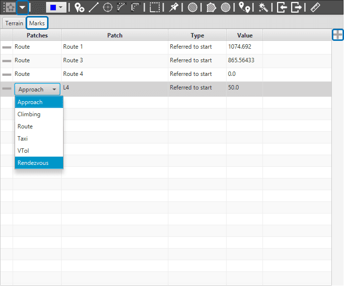
Marks Menu and Guidance’s patch selection
There are several options to configure the Marks:
Patches: by double-clicking on “Route”, a dropdown list allows the user to select different flight phases where the marks will be placed: Approach, Climbing, route… Except for Route patches, the rest of the phases are generated when the user, or an automation, activates them. As the user can not select this patches, they do not already exits, this option will create the mark automatically in the patch selected.
Patch: Most Flight phases have predefined patches with specific names. The user can select where the mark will be placed on those patches. At the end of this section there is a table that summarizes available options. For more information about them, check the Control menu in Setup Toolbar.
Type: right now the only possible option is “Referred to Start” of the selected patch.
Value: Mark’s distance to the start of the patch.
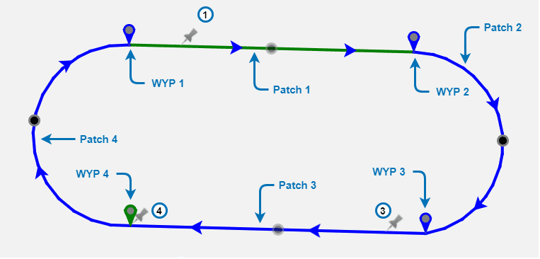
Route Patches
At the examples above there are four marks created. Three are attached to different route patches: 1,3 and 4. Route 1 and Route 3 marks were added by hand. Route 4 mark was introduced using this menu and is overlapping with waypoint 4 (value equals zero). Last mark was added to the approach L4 patch. This mark could be linked to an automation that deploys landing flaps, for example.
Approach |
L0/A1/L2/A3/L4/L5 |
Climbing |
L4/A3/L2/A1 |
Route |
512 patches |
Taxi |
Taxi1/Taxi2 |
VTol |
VTol1/VTol2/VTol3 |
Rendezvous |
Rendezvous1/Rendezvous2/Rendezvous3 |
