Dealing with PDI files
Before Pipe v.6.6
Veronte_SD_image.img contains all the configuration information. PDI are uploaded exactly the same way that would be uploaded to a physical autopilot. Once connected to Veronte Pipe, a virtual autopilot will be detected in safe mode. So the steps to upload/change the PDI configuration are:
Run Simulink model: to be able to upload new PDI files the virtual autopilot must appear in pipe. So the SIL simulation must start in order to send the proper information.
Enter autopilot in maintenance mode: then stop the simulation and press run again.
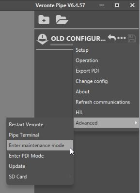
Enter Maintenance mode
Upload a new PDI file: Once the virtual autopilot appears in maintenance mode, press on change configuration. Select your PDI files and exit from maintenance mode. Stop Simulink.
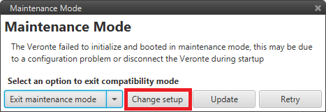
Change setup
Run Simulink with the correct configuration.
After Pipe v.6.6 (Included) - PDI builder
Open VeronteLink and create an Ethernet connection (Connecting to Pipe).
Run Simulink Model to simulate the autopilot information. Check autopilot information appears in VeronteLink.
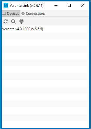
Veronte Link
Open PDI Builder and select your autopilot. Then click on link button (5). PDI Builder Interface allows the user the following actions : Create or modify PDI files offline (1), upload PDI configuration to the autopilot (2), open the autopilot configuration to modify it (3), change between maintenance and normal mode (4).
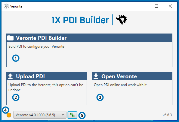
PDI builder
If you want to modify a SD image click on (3).
If you want to upload your PDI files, change to Maintenance mode (4). Stop the Simulation and press run again. Now the autopilot selected has an orange color. Press Upload PDI (2) and select the new configuration. Exit maintenance mode (4).