Technical
Main Features
The block diagram of the system is shown below.
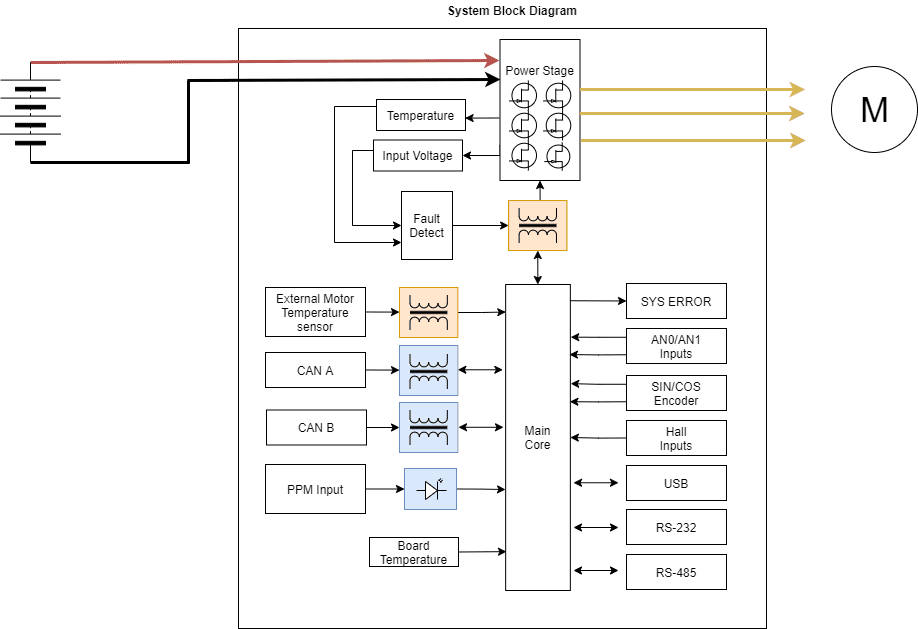
Peripheral used for motor control
Opto Isolated PWM
CAN bus
Peripheral use for ESC telemetry
Serial RS-232
Serial RS-485
USB
Any of the serial interfaces can be used to configure the internal variables of the MC24.
The ESC includes an internal SD memory which is used to record operating logs. The variables to store can be selected through the corresponding interface.
Note
If serial interface is used for motor control, it cannot also be used to send telemetry, and vice versa.
On the contrary, with CAN bus users can control and send telemetry at the same time.
Mechanical Specifications
Weight: 2430 g.
Operating temperature: -40°C to 55 °C.
Dimensions:
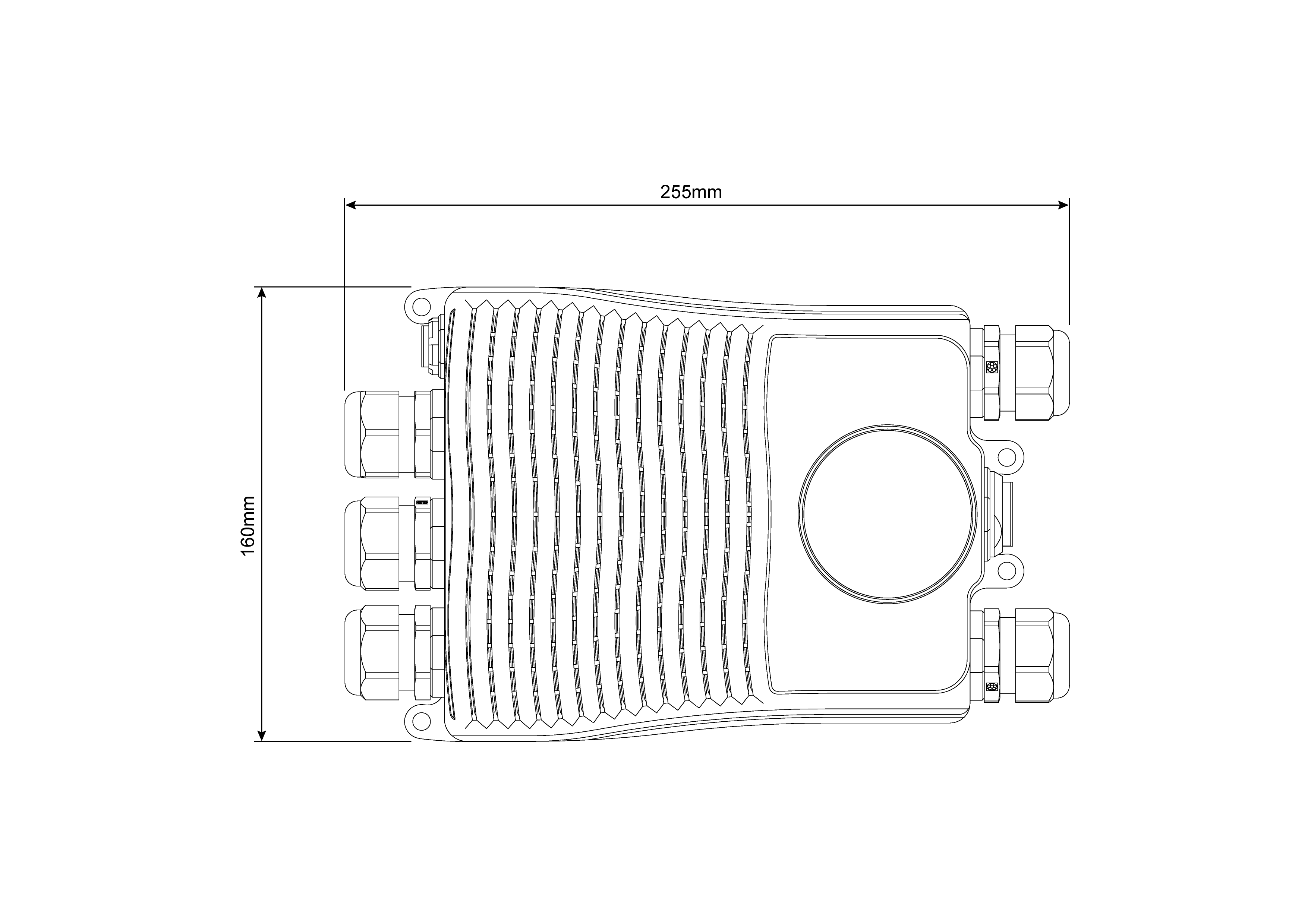
Dimensions in mm
Electrical Specifications
Specification |
Value |
|---|---|
Voltage |
60-120 V DC |
Current |
Input from battery: 200 A |
Output to motor: 200 A (rms value) |
|
Peak current (< 5 s) |
Input from battery: 400 A |
Output to motor: 400 A (rms value) |
|
Maximum speed (1 pole) |
600000 ERPM |
PWM frequency |
10 kHz |
Interfaces
VCC
This is the main power input for the secondary part of the driver. It must be powered with a voltage of 8 to 20 V.
The consumption of this pin also depends on the loads connected to 5 V pin.
Status |
Value |
|---|---|
Standby |
6.6 W |
Active |
13.2 W |
Note
No load on 5 V output.
HALL Inputs
Warning
The employed hall sensors must not exceed 5 V.
These inputs are used to add to the system a feedback in sensored mode (incremental type, usually magnetic).
The 3 Hall effect sensors must be placed at 120° (electrical degrees) from each other. The following is a simple formula for obtaining the mechanical degrees of separation when installing the sensors:
So the sensors must be placed one of each other at:
For example, for 10 pole pairs:
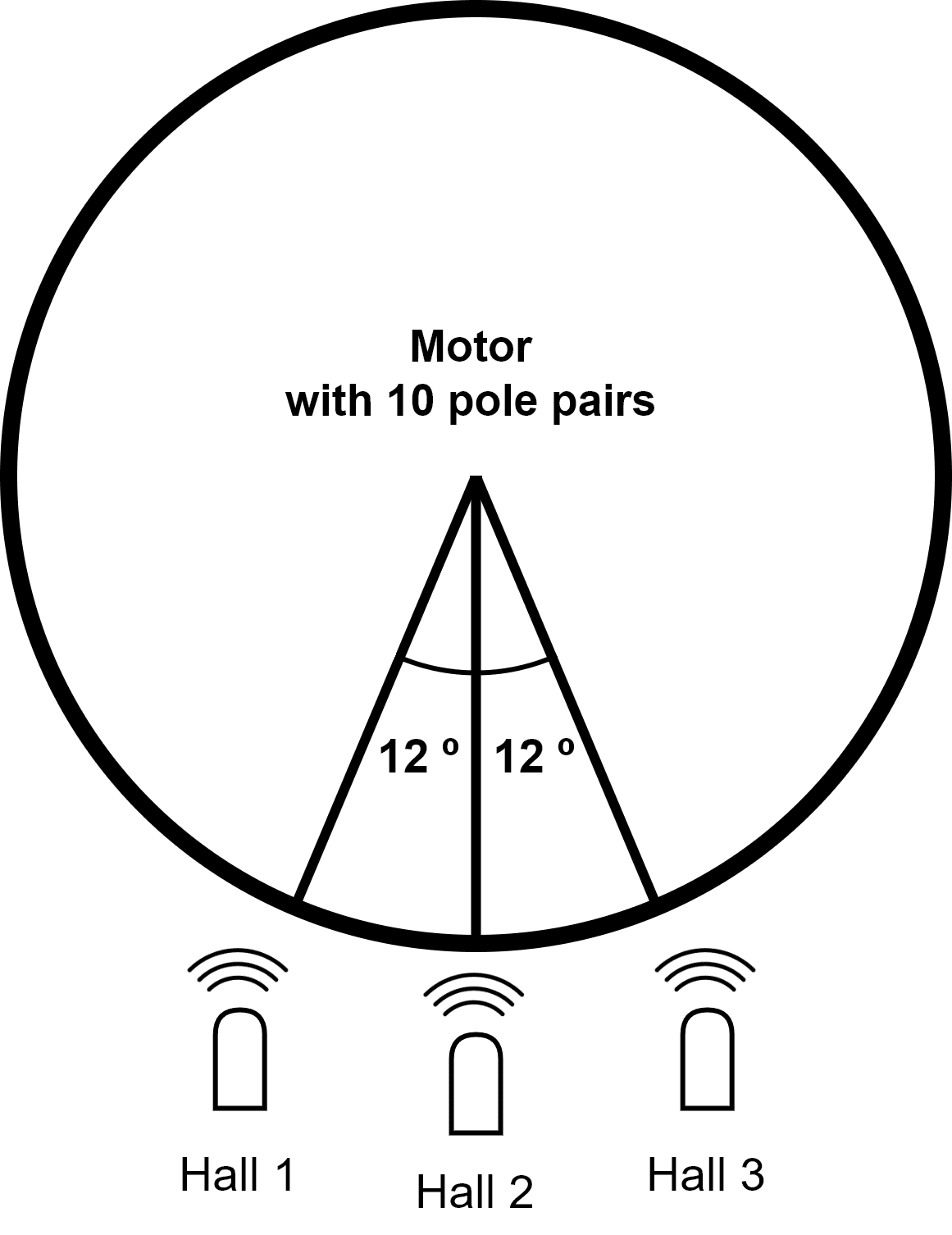
Example diagram
Tip
The arc length between sensors can be calculated as follows:
FAN_PWM
This 0-3.3V output is used to control an external fan in case it is needed.
Opto PWM Input
This input is an optocoupled control digital signal.
The input is interpreted as 0-100 % of the maximum RPM. An initial dead band can be configured to prevent the engine from starting.
Type |
Specification |
|---|---|
Input voltage range |
0-5 V |
Minimum input current |
2.5 mA |
Maximum frequency |
250 Hz |
NTC/PTC Input (External Temperature Sensing)
A PTC or NTC sensor can be integrated. The maximum voltage on this pin is 2 V.
The PTC/NTC should be connected on the low side of an external resistor divider. This is the configuration by default. A high side connection can be used too, but a custom modification is needed.
The isolated Voltage_ref output should be left floating in default mode. The iso_ground is the return path of the NTC/PTC sensor.
ERROR_SIGNAL
This signal indicates if there is an error within the MC24. A positive voltage of 3.3 V means that there is no problem.
SIN/COS_SIGNAL
These signals are those dedicated to the SIN / COS type analog sensor. There is a 100 kohms resistor to act as divider so the maximum voltage on the pin does not exceed ±250 mV.
USB
This is the interface normally used to configure the MC24 internal parameters.
The connection and disconnection of the USB related signals should always be done when the power supply (via the VCC input) is on.
Note
Not recommended for sending telemetry by default.
RS-232
Single ended serial type protocol:
Type |
Specification |
|---|---|
ESD Protection |
±15 kV (HBM) |
Requirements |
TIA/EIA-232-F and ITU v.28 |
Speed |
Max. 250 kbit/s |
Input Voltage |
-25 to 25 V |
Output Voltage |
-13.2 to 13.2V |
RS-485
Differential serial type protocol:
Type |
Specification |
|---|---|
ESD Protection |
±15 kV (HBM) |
Requirements |
TIA/EIA-485-A |
Speed |
Max. 25 Mbit/s |
Input Voltage(D) |
-0.5 to 7 V |
Output Voltage (D) |
1.5 to 2.4 V |
CAN
Differential communication protocol:
Type |
Specification |
|---|---|
ESD Protection |
±4 kV (HBM) |
Requirements |
ISO11898-2 |
Speed |
Max. 5 Mbit/s |
Input Voltage(D) |
-12 to 12 V |
Output Voltage (D) |
2.9 to 4.5 V |
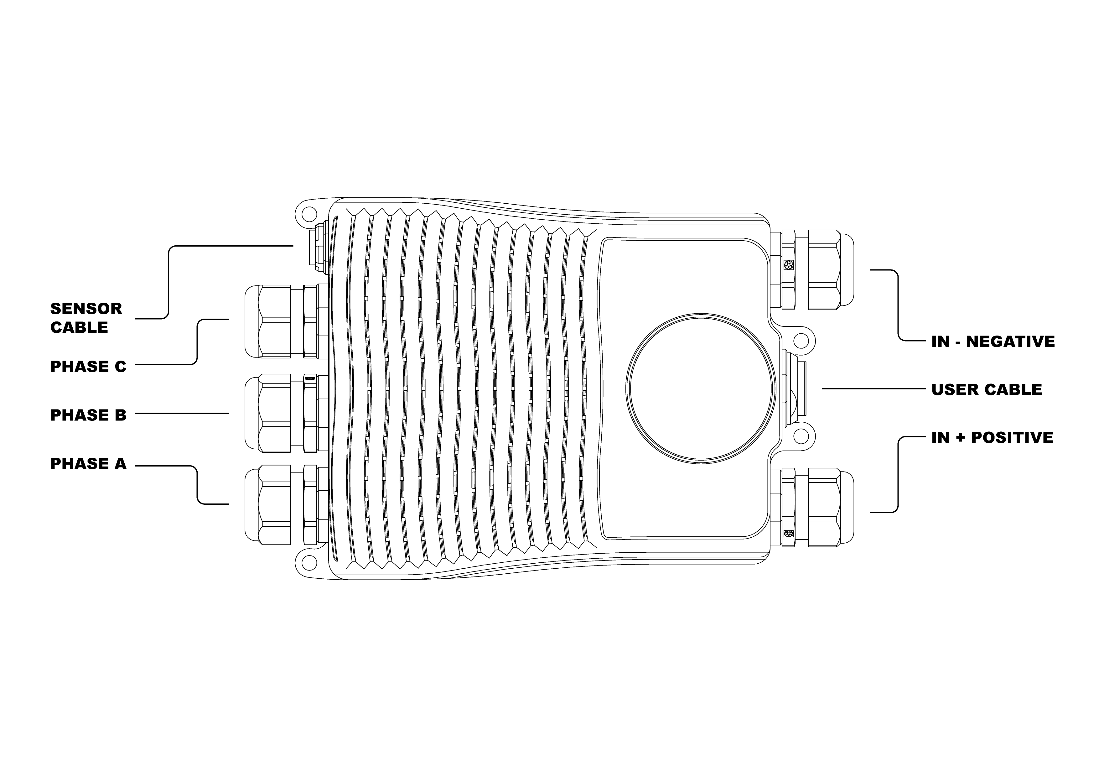
Mating connectors
The connectors references are shown in the next figure and table.
Name |
Embention reference |
|---|---|
Sensor cable |
P001635 |
Phase C |
P005590 |
Phase B |
|
Phase A |
|
In negative |
|
In positive |
|
User cable |
P001634 |